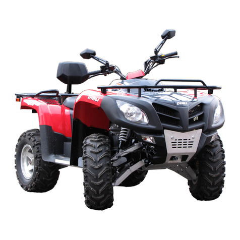
KAYO MOTOR AU200 User manual

1
KAYO MOTO
AU200
Maintenance Manual

3
Kayo Moto
2018- 08
Description
This manual specificially descripted
the maintenance adjustment procedures
for the AU200 four-wheels vehicle (ATV),
disassembly and assembly methods,
inspection and maintenance points,
troubleshooting methods and
maintenance technical data, and detail
graphic data.
Please read this manual carefully and
follow the standard operating methods to
effectively extend the service life of each
component, improve engine performance
and vehicle reliability.
The first chapter mainly introduces
general work items, tools used, basic
technology and maintenance parameters.
The second chapter introduces the
assembly and disassembly operation of
the whole vehicle plastic parts.
The third chapter introduces the
regular inspection and adjustment of the
whole vehicle.
The fourth chapter introduces the
disassembly of the engine peripheral
assembly parts.
The fifth chapter introduces the
methods and notice for disassembly,
inspection, maintenance and assembly of
various parts of the engine.
Chapter 6 introduces vehicle chassis
related information
Chapter 7 introduces the inspection
and maintenance information of the
vehicle signal and lighting system.
Appendix: Electrical Schematic
The contents of this manual are subject
to change without further notice due to
improvements in the vehicle.
Maintenance should be based on the
actual state of the vehicle.
Kayo Moto
Research and Development Department
2018 - 08
Contents
Maintenance information
1
Body Plastic
2
Regular inspection and
adjustment
3
Engine periphery
4
Engine
5
Vehicle chassis
6
Signal and lighting system
7
Electrical schematic
appendix

4

浙江华洋赛车股份有限公司
5
Unit conversion table
Item
Unit conversion
Pressure
1kgf/cm2=98.0665kPa;1kPa=1000Pa
1mmHg=133.322Pa=0.133322kPa
Torque
1kgf·m=9.80665N·m
Volume
1mL=1cm3=1cc
1L=1000cm3
Force
1kgf=9.80665N
Length
1in=25.4mm
Warning
Please read the following explanation carefully, which emphasizes the
specific meaning of the words “danger”, “warning” and “attention”, and pay
special attention to the outstanding meaning of the engine when repairing it.
Danger: Be alert to high risk
Warning: Indicates caution against moderate risks
Note: Indicates concern for mild danger
However, please note that the “Danger” and “Warning” contained in this
Manual are unlikely to cover all potential risk during engine use and maintenance.
Therefore, in addition to the relevant provisions of “danger” and “warning”,
maintenance operator must also have basic mechanical safety knowledge. If you
are not sure of completing the entire maintenance operation, please consult a
more experienced senior technician.


浙江华洋赛车股份有限公司
1-
1
1 Maintenance information
1.1Notes for Operation……………………………………………………………………………1-1
1.2 Vehicle identification number…………………………………………………………………1-3
1.3 Main parameter list……………………………………………………………………………1-4
1.4 Maintenance parameter list……………………………………………………………………1-6
1.5 Tightening torque………………………………………………………………………………1-8
1.6 Lubricant, sealant………………………………………………………………………………1-10
1.7 Cable, hose, cable wiring diagram……………………………………………………………1-11
1.1 Work precautions
Safety Precautions
1. Work clothes (such as overalls), hats, and safety boots that are suitable for the work must be worn.
If necessary, wear protective glasses such as dust-proof glasses, dust masks, gloves, etc. to protect
your body.
2. Since the exhaust gas contains harmful components, it is forbidden to operate the engine for a long
time in a closed place and a place with poor ventilation.
3. When the engine is stopped, the temperature of the engine and muffler is still very high. Do not
touch before cooling to avoid burns.
4, Battery solution (dilute sulfuric acid) is a strong corrosive agent, there will be burns, blindness
when exposed to the skin, eyes. If the clothes and skin are inadvertently stained with the battery
solution, rinse immediately with plenty of water and go to the hospital for treatment. The battery and
battery solution should be kept strictly and must be kept in a safe place that children can't get. When
the battery is charged, it will produce flammable and explosive hydrogen. If there is a fire source or
an electric spark is approaching, there is a danger of explosion. Please charge in a well ventilated
area.
5. Since gasoline is a flammable item, fireworks are strictly prohibited at the work site. Not only pay
attention to open flames, but also pay attention to electric sparks. In addition, there is a danger of
explosion of vaporized gasoline. Please choose a well-ventilated site for work.
6. Be careful not to let the rear wheel, clutch and other rotating parts and movable parts clamp the
hands and clothes at any time during maintenance.
7. When two or more people work together, they must constantly greet each other to confirm safety.
Disassembly and assembly precautions
1. Parts, lubricants and greases must be recommended by Huayang brand.
2. Separate and store the parts of each system separately so that the parts can be returned to their
original positions.
3. Please clean the dirt and dust on the car before maintenance.

1维修信息
1-
2
4. The gasket, O-ring, piston pin retaining ring, split pin, etc. must be replaced with new ones after
disassembly.
5. If the opening of the circlip is too large when disassembling, it will be deformed and will fall off
easily after reassembly. Please do not use elastic circlips that are already loose and lose their
elasticity.
6. After the parts are disassembled and inspected, clean them before the measurement and blow off
the cleaning agent with compressed air. Apply lubricant to the moving surface before assembly.
7. When disassembling, check the necessary places and measure the relevant data so that it can be
restored to the state before disassembly during assembly.
8. Fasteners such as bolts, nuts and screws should be pre-tensioned and then tightened according to
the specified tightening torque on the diagonal according to the principle of being large to small and
from the inside to the outside.
9. Rubber parts should be inspected for aging when disassembled, and replaced if necessary. In
addition, since the rubber parts are not resistant to corrosion by gasoline or kerosene, try not to allow
volatile oils and greases to adhere to them.
10. Apply or inject the recommended grease at the designated location in accordance with the
requirements of the service manual.
11. The correct special tools should be used for disassembly and assembly.
12. The ball bearing can be rotated by the inner ring or the outer ring with the finger to confirm
whether the rotation is flexible and smooth. If the disassembly method of applying force on the ball
is taken during disassembly, the removed bearing should not be used any more:
Replace the bearing axial and radial clearance too large.
Rotating bearings with stuck sensation should be cleaned. After cleaning, the stuck ones should
be replaced and cannot be cleaned directly.
It is originally pressed tightly with the body or shaft diameter, and the bearing should be replaced
when the fit is not tight.
13. The bearings should be coated with oil or grease before assembly. Single-sided dust-proof
bearings should pay attention to the installation direction when assembling. Open or double-sided
dust-proof bearings should be assembled with the manufacturer's logo and dimensions facing out
when assembling.
14. When installing the rectangular retaining ring, the chamfered side should face the direction of the
force. Do not use the retaining ring that has lost its elasticity. After assembly, turn the rectangular
retaining ring to confirm that it is firmly seated in the slot.
15. After assembly, it is necessary to check whether the fastening parts are tightened and the work is
normal.
16, brake fluid and coolant will damage the painted surface, plastic parts, rubber parts, etc., do not let
it adhere to such parts, in case of adhesion, immediately rinse with water.
17. The oil seal should be installed with the side marked by the manufacturer facing outward
(without oil):

浙江华洋赛车股份有限公司
1-
3
When assembling, be careful not to curl the oil seal lip and prevent the burr from scratching the
oil seal lip.
Apply grease to the oil seal lip before assembling.
18. When installing the hose parts, insert the hose into the joint root. There is a pipe clamp to install
the pipe clamp in the recessed mark of the pipe. Replace the hose without tightness during
installation.
19. Do not put dust, dirt, etc. inside the engine and the hydraulic system of the brakes.
20. The gasket material attached to the joint surface of each box of the engine should be cleaned
before assembly. The bumps on the contact surface must be uniformly removed by grinding with oil
stone.
21, The cable type should not be excessively twisted and bent. Deformed and damaged cables can
cause malfunction or breakage.
22. When assembling the cap parts, the groove must be inserted into the groove.
Engine running-in
The engine has many components for relative movement, such as pistons, piston rings,
cylinder blocks, intermeshing transmission gears, etc. Therefore, in the initial stage of its
use, it is necessary to carry out standard running-in, and the running-in can make the
moving parts adapt to each other and correct. The working gap forms a good smooth
friction surface that can withstand large loads, and the engine that has been run-in is
standardized to have excellent performance and reliability.
The recommended run-in time is 10 hours and the specifications are as follows:
0 to 10 hours: Avoid continuous operation in the state of more than 1/2 throttle. Always
change the speed. It is not recommended to operate for a long time under a fixed throttle
position. After 1 hour of operation, cool the engine for 5 to 10 minutes; Accelerated
acceleration, the throttle change should be slow, not sudden and small, do not drag the
cargo during the running-in.
Note:
Maintenance during the running-in period according to the daily maintenance
regulations, and find out the faults in time;
After the running-in is completed, the whole machine can be ma intained after the
running-in period before entering the normal driving stage .
1.2 Vehicle identification number

1维修信息
1-
4
1 VIN on chasis
2 Vehicle name plate
3 Engine number
Model
AU200
VIN
L6JACMLA5G ~
Engine number
F1702K ~
1
3
2


1维修信息
1-
4
1.3 Main parameter list
Item
Parameter
Model
AU200
Length(mm)
1786
Width(mm)
955
Height(mm)
1050
Wheelbase(mm)
1120
Engine model
LC162FMC-2
Total displacement(ml)
200
Fuel type
No.92 and above gasoline
Vehicle Dry weight (kg)
180
Number of Passenger
1 person(driver)
Maximum loading weight
1 person +60kg = 120kg
Tire
specifications
Front
AT23×7-10
Rear
AT22×10-10
Minimum ground clearance
175mm
Turning circle diameter (nearest point
minimum turning diameter)
3000mm
Engine
Starting method
Electric start
Engine type
Single cylinder, four stroke, air cooling
Air distribution
SOHC/Chain drive
Cylinder diameter ×
stroke(mm)
62 ×58.4
Compression ratio
9.7 : 1
Lubrication method
Wet
Oil pump type
Rotor type
Lubricating oil filter type
Full flow filter rotary
No. of machine oil
SAE15W-40/SF and above
Cooling
air

浙江华洋赛车股份有限公司
1-
5
Item
Parameter
Air filter type
Sponge filter
Throttle body
Model
Plunger throttle
Mixing valve diameter
30mm
Fuel tank volume
9L
Transmission
system
Clutch type
Dry automatic clutch
Variable speed mode
(CVT)
Gear shift position
One forward gear, one neutral gear, one
reverse gear
Shift mode / sequence
Hand operation/F—N—R
(CVT)Stepless speed
ratio
0.95~2.8
Output type
Rear axle output
Direction of rotation
of Engine output
In the forward gear, it is clockwise from the
rear of the vehicle.
Steering device
Steering angle
inside
32°
outside
24°
Brake type
front
Hydraulic disc
rear
Hydraulic disc
Buffer mode
Suspension method
Front wheel double rocker independent
suspension, rear wheel non-independent
suspension
Frame
Steel pipe welded

1维修信息
1-
6
1.4 Maintenance parameter list
Lubricating device
Item
Standard
limited
Engine oil
capacity
Change oil
800ml(No oil filter replaced)
-
Change oil
900ml(oil filterreplaced)
Full capacity
1000ml
-
Recommended engine oil
OnlyuseSAE 15W/40-SE,Do not substitute or
mix different grades of engine oil, which will
cause damage to the engine and cause an
accident.
Oil pump rotor
Inner and outer rotor radial
clearance
-
0.12mm
clearance between outer rotor and
pump body
-
0.12mm
clearance between rotor surface
and pump bodyaxial
0.05~0.1
0.2mm
Intake system ( 05-Engine section for details)
Wheel(front and rear are the same)
Item
Standard
limited
Wheel pulsation
vertical
0.8mm
2.0mm
horizontal
0.8mm
2.0mm
wheel
Residual trench
-
3mm
Air pressure
35kPa(0.35kgf/cm2)
-
Brake system
Item
Standard
limited
Front brake
Brake disc thickness
3.5mm
3.0mm
Rear brake
Brake handle stroke
2 ~ 6mm
-
Brake disc thickness
4.0mm
3.0mm

浙江华洋赛车股份有限公司
1-
7
Battery / charging device / trigger coil
Item
Standard
Magneto
model
Permanent magnet alternator
output
Three-phase full wave
Magneto-triggercoilresistance
150
Magneto no-loadvoltage (engineisin cold
state)
no
Magnetomaximumoutputpower
180w
Stablevoltage
14.5 ±0.5V
Triggercoil Maxvoltage
≥1V,200r/min;≥8.5V,2000r/min
Rectifier type
Full wave rectification
Battery
capacity
12V7Ah
Voltage between
terminals
Fullycharged
14.4V
No Fully
charged
Less than 11.8V
Ignition device
Item
Standard
Ignition method
CDI Electronic ignition
Spark plug
model
Resistive spark plug
standard
D8RTC
Spark plug gap
0.6~0.7mm
Spark
characteristics
Blue and white light
Ignition coil
resistance
primary
0.3 Ω
Secondary
3.8 kΩ
Max voltage
Primary Ignition
coil
300~450V
Pulse generator
20kV~30kV
Startingrelaycoilresistance
3.5 Ω

1维修信息
1-
8
Light / instrument / switch
Item
Standard
fuse
10A
Light, bulb
Headlight
12V—35W
Front turnlight
12V—10W
Rear light / brake light
12V—2.8W
Rear turn light
12V—2.5W
Position light
12V—3W
Valve + cylinder head ( section 05 - Engine)
Cylinder + Piston + Piston Ring + Crank Link (section 05 - Engine )
Clutch + transmission(section 05 - Engine)

浙江华洋赛车股份有限公司
1-
9
1.5 Fastener tightening torque
Note:
Put some rust-proof grease to the threaded part and the joint before installing the thread
Tightening torque at the specified part - the entire vehicle part
No.
Item
Fastener code
quantity
Tightening torque
(N·m)
1
Suspension lower rocker bolt
GB5789 M10×1.25×80
4
45~59
2
Front and rear shock absorbing bolts
GB5787 M10×1.25×40
6
45~59
3
Front hub mounting slotted nut
GB9457 M14×1.5×H18
2
126~218
4
Steering rod ball pin slotted nut
GB9457 M10×1.25
4
33~45
5
Directional cap screw
GB70-85 M8×35
4
22~30
6
Front brake caliper body bolt
GB5789 M8×25
4
22~30
7
Front brake disc bolt
M8×1.25×20
8
22~30
8
Rear brake caliper body bolt
GB5789 M8×25
2
22-30
9
Rear brake disc mounting screw
GB70-85 M8×16
4
22~30
9
Directional mounting bolt
GB5783 M10×1.5×30
2
45~59
12
Oil cooler mounting bolt
GB5789 M6×25
4
9~12
13
Tow ball fixing plate mounting screw
GB70-85 M10×1.5×30
4
45~59
14
Rear hub mounting slotted nut
GB9457 M16×1.5
2
199~311
15
Steering column mounting slotted nut
GB9457 M12×1.25
1
110~130
16
Steering column clamp mounting bolt
GB5787 M8×60
2
22~30
17
Fuel tank front mounting bolt
GB5789 M6×25
2
9~12
18
Fuel tank rear mounting bolt
GB5789 M6×30
2
9~12
19
Horn mounting bolt
GB5787 M6×16
1
9~12
20
Negative pressure switch bolt
GB5787 M6×16
1
9~12
21
Engine mounting bolt
GB5787 M10×1.25×160
1
45~59
22
Sprocket seat mounting screws
GB70-85 M8×20
4
38~51
23
Plastic base mounting screw
GB70-85 M6×45
4
13~16
24
Crosshead self-tapping screws
GB845-85 ST4.2
—
—
25
Crosshead screw
GB828-88 M5×16
2
—
26
Crosshead flat screw
TM6
—
—
27
Rim mounting nut
GB6187-86 M10×1.25
16
45~59

1维修信息
1-
10
Tightening torque at the specified location - engine section ( section 05-Engine )
tightening torque at the unspecified location
kind
Torque N·m
kind
Torque N·m
5mm Bolts and nuts
4.5~6
5mm Screw
3.5~5
6mm Bolts and nuts
8~12
6mm Screw
7~11
8mm Bolts and nuts
18~25
6mm Convex bolt
10~14
10mm Bolts and nuts
30~40
8mm Convex bolt、Screw
20~30
12mm Bolts and nuts
35~50
10mm Convex bolt、Screw
30~40
Engine repair tool (section 05-Engine)
Engine-specific tools (section 05-Engine)
1.6 Lubricating grease, sealant
location
note
Kind of grease
Steeringbearing
Light lithium soap grease
Throttle cableconnection
Rocker arm
Directional column inner
circumference
Cushionlockactivepart
Shiftingmechanism activepart
Cables, bearings, and manipulating lubrication parts
location
note
Kind of grease
Steering shaft spherical bushing
lubrication
Automotive universal
lithium grease
GB/T5671
Rear wheel axle supporter
Front and rear shock absorber joints
Throttle handle shaft and cable
connector
Left and right brake handle shaft
Parking cable connection
Engine running materials and installation accessories(section 05-Engine)

浙江华洋赛车股份有限公司
11
Engine operating materials include lubricating oil (oil), grease (butter) and coolant;
installation accessories include flat sealant, thread locker, etc.
1.7 Cable, hose, cable wiring diagram
1. Headlight connector 2. Left turn signal connector 3. Left hand multi-function switch
connector 4. Instrument connector 5, right turn signal connector 6, electric door lock switch
connector
Note: The front panel must be removed before inspection of the above components.
For specific disassembly,check Chapter 2 Body Covers.
1
2
3
4
5
6
1

1维修信息
1-
12
7, brake sensor (left one and right one) 8, throttle line 9, brake hose
1. Motor line 2. Crankcase exhaust pipe 3. Carburetor 4. Carburetor drain pipe 5. Magnetic
motor trigger connector
Note: The right foot pedal and the right middle guard must be removed before
inspection and maintenance of the above components.
7
8
9
1
2
3
4
5
Table of contents
Other KAYO MOTOR Offroad Vehicle manuals

KAYO MOTOR
KAYO MOTOR AY70-2 User manual

KAYO MOTOR
KAYO MOTOR JACKAL 200 User manual

KAYO MOTOR
KAYO MOTOR STORM 150 User manual

KAYO MOTOR
KAYO MOTOR AU180 User manual

KAYO MOTOR
KAYO MOTOR HY110AT User manual

KAYO MOTOR
KAYO MOTOR AU125 User manual

KAYO MOTOR
KAYO MOTOR A180 User manual

KAYO MOTOR
KAYO MOTOR AT125-B User manual

KAYO MOTOR
KAYO MOTOR AU110 User manual

KAYO MOTOR
KAYO MOTOR FOX 70 User manual