KEBCO COMBISTOP 38 User manual

01.09.2011 Rev. 01 COMBISTOP Type 38

01.09.2011 Rev. 01 COMBISTOP Type 38
Version 01
Date: September 2011
© Karl E. Brinkmann GmbH
This instruction manual and all figures contained therein are protected by copyright. Without the
prior written consent of the publisher, any use of this manual which infringes the copyright
provisions is not permitted and will lead to legal prosecution. This particularly applies to the
reproduction, translation, digital storage, and processing in electronic systems.

Table of Contents
01.09.2011 Rev. 01 COMBISTOP Type 38 Page I
Table of Contents
1Introduction ...................................................................................................................1
1.1 Means of Representation.................................................................................................2
1.2 Safety Instructions...........................................................................................................2
1.2.1 General Safety Instructions .............................................................................................3
1.2.2 Safety Instructions for Operation .....................................................................................4
1.2.3 Safety Instructions for Maintenance.................................................................................4
1.2.4 Permissible Friction Work ................................................................................................4
1.2.5 Special Risks when Using the Brake ...............................................................................4
1.2.6 Risks Caused by Electric Power ......................................................................................5
1.2.7 Personal Protective Equipment .......................................................................................5
1.3 Obligation of the Operating Company..............................................................................5
1.4 Obligation of the Personnel .............................................................................................6
1.5 Specified Application .......................................................................................................6
1.6 Guarantee and Liability....................................................................................................7
2Product Description ......................................................................................................8
2.1 Overview/Parts List..........................................................................................................8
2.2 Functional Description .....................................................................................................9
2.3 Safety Devices ................................................................................................................9
2.3.1 Micro Switch (Option) ......................................................................................................9
3Transport and Storage ................................................................................................10
3.1 Inspections on Acceptance by the Recipient .................................................................10
3.2 Notes on Transport........................................................................................................10
3.3 Packaging .....................................................................................................................10
3.4 Storage Instructions for Temporary Storage ..................................................................10
4Mounting and Start-up ................................................................................................11
4.1 Mounting .......................................................................................................................11
4.1.1 Notes on Mounting ........................................................................................................11
4.1.2 Mounting the Brake .......................................................................................................12
4.1.3 Mounting the Hand Release (Option) ............................................................................14
4.1.4 Micro Switch (Option) ....................................................................................................17
4.1.4.1 Replacing the Micro Switch ...........................................................................................18
4.1.4.2 Checking the Micro Switch Settings...............................................................................19
4.1.4.3 Readjusting the Micro Switch ........................................................................................20
4.1.5 Electrical Connection.....................................................................................................21
4.1.5.1 Connecting the Brake ....................................................................................................22
4.2 Initial Start-up ................................................................................................................24
4.2.1 Inspections prior to Start-up of Brake ............................................................................24
4.2.2 Notes on Running-in Process ........................................................................................24
5Operation .....................................................................................................................25
5.1 Actuating the Hand Release ..........................................................................................25
6Malfunctions ................................................................................................................26
Table of Contents
01.09.2011 Rev. 01 COMBISTOP Type 38 Page II
6.1 Safety Instructions.........................................................................................................26
6.2 Troubleshooting.............................................................................................................27
7Maintenance and Cleaning .........................................................................................28
7.1 Safety Instructions.........................................................................................................28
7.2 Maintenance Intervals ...................................................................................................28
7.3 Maintenance Work.........................................................................................................29
7.3.1 Checking the Air Gap ....................................................................................................29
7.3.2 Readjusting the Air Gap ................................................................................................30
7.3.3 Replacing the Lining ......................................................................................................31
7.4 Notes on Cleaning.........................................................................................................33
8Dismounting and Disposal .........................................................................................34
8.1 Dismounting ..................................................................................................................34
8.2 Disposal ........................................................................................................................34
9Annex ...........................................................................................................................35
9.1 Technical Data ..............................................................................................................35

Introduction
01.09.2011 Rev. 01 COMBISTOP Type 38 Page 1
1 Introduction
This instruction manual provides all information required to properly operate the KEB
brake and applies to the following brake types:
–COMBISTOP Type 38
COMBISTOP Type 38.11N
without hand release for dynamic applications (regular rated torque)
COMBISTOP Type 38.13N / DEN
with hand release for dynamic applications (regular rated torque)
COMBISTOP Type 38.11H
without hand release for static applications (enhanced rated torque)
COMBISTOP Type 38.13H / DEH
with hand release for static applications (enhanced rated torque)
The type designation can be found on the type plate and/or the code number.
The instruction manual must be read, understood and applied by all persons
responsible for the operation of the brake. This particularly applies to the safety
instructions herein.
After reading the instruction manual, you can
–operate the brake safely,
–perform maintenance work according to regulations,
–take the corresponding measure in case of a malfunction.
Before starting to install the COMBISTOP type 38 brake, carefully read this instruction
manual.
The following sections describe the functional principle, the mounting and the basic
operation of the brake.
The information contained in the technical documentation, as well as any user-specific
advice in spoken and written form and through tests, are made to best of our
knowledge and information about the application. However, they are considered for
information only without responsibility. This also applies to any violation of industrial
property rights of a third party.
Inspection of our units in view of their suitability for the intended use must be done
generally by the user.
Application and use of our units in the target products is outside of our control and
therefore exclusively in the area of responsibility of the user.
In addition to this instruction manual, observe all applicable legal regulations and other
mandatory requirements applying to accident prevention as well as environmental
protection in the country of utilisation.
Always keep the instruction manual at the site where the brake is used.

Introduction
01.09.2011 Rev. 01 COMBISTOP Type 38 Page 2
1.1 Means of Representation
For information purposes as well as to directly warn the operator of dangers, any
information given in this instruction manual which needs to be strictly observed is
marked as follows:
Note!
This symbol is used to indicate notes on a function and/or setting or
on the importance of being cautious when working.
This symbol in connection with the respective signal word is used to
indicate the following important instructions:
–Caution!
Is used to indicate a hazardous situation with a low level of risk
which could result in minor or moderate bodily injuries or material
damages if the warning is ignored.
–Warning!
Is used to indicate a possibly hazardous situation with a medium
level of risk which may result in death or (severe) bodily injuries if
the warning is ignored.
–Danger!
Is used to indicate an imminently hazardous situation with a high
level of risk which will result in death or (severe) bodily injuries if the
warning is ignored.
Caution!
Warning!
Danger!
Warning - Dangerous Electrical Voltage!
This symbol is used to indicate electrical hazards.
Only qualified and authorised electricians may work on electrical
equipment!
Danger!
In addition, the following means of representation are used:
–Any text following this marking is considered a list.
Any text following this marking describes the actions which need to be executed in
the specified order or which are automatically executed.
"..." Any text marked by quotation marks refers to other chapters or sections.
1.2 Safety Instructions
Note!
Carefully read the safety instructions and hazard warnings outlined in
this section prior to mounting and start-up of the brake!

Introduction
01.09.2011 Rev. 01 COMBISTOP Type 38 Page 3
1.2.1 General Safety Instructions
Prior to mounting and start-up, carefully read the instruction manual, particularly
observing the safety instructions and recommendations therein. Failure to comply with
these instructions may result in personal injury and material damages. Furthermore,
observe the state of the art as well as all applicable safety regulations and standards of
the respective countries.
The spring-applied brake corresponds to the state of the art at the time of delivery and
is generally safe to operate.
Only qualified personnel may transport, mount, start up, operate and maintain the
brake.
Qualified personnel in the context of these general safety instructions refers to persons
who are familiar with the transport, mounting, installation and commissioning of the
brake as well as with the relevant standards, and who are sufficiently qualified in their
field of expertise.
–Only trained personnel may commission the brake.
–Immediately put the brake out of operation in case of malfunctions. Have
appropriately trained personnel or the manufacturer correct the malfunctions.
–Do not exceed the technical performance data (see section "9.1 Technical Data").
–Never use the brake in potentially explosive or aggressive atmospheres!
–The brake must not be converted, modified or misused.

Introduction
01.09.2011 Rev. 01 COMBISTOP Type 38 Page 4
1.2.2 Safety Instructions for Operation
Protective measures to be taken by the user:
–Protection against the ingress of foreign particles into the air gap. These particles
may impede the movement of the armature.
–Protection against dangerous temperatures at the magnet of the brake.
High temperatures may cause the torque to decrease.
–Protection against accidental contact with rotating or moving parts, i. e., protection
against being crushed or caught.
–Never use the brake in potentially explosive or aggressive atmospheres!
–Protection against electric shock by installing a protective earth conductor between
the magnet and the fixed installation incl. standardised inspection of the protective
earth conductor connection to all exposed metal parts.
–Measures against freezing and/or formation of ice on the friction surfaces and the
resulting loss of torque.
–The movement of the armature must not be impeded by the ingress of foreign
particles into the air gap. If necessary, dust protection rings (accessories) are to be
used or other protective measures are to be taken.
–Air humidity, aggressive vapours/liquids or the like may lead to corrosion and cause
the lining to stick. In this case, the user needs to provide appropriate measures!
1.2.3 Safety Instructions for Maintenance
Protective measures to be taken by the user:
–Secure the brake against being switched on accidentally during maintenance work.
–When working on the brake, disconnect the brake from load to avoid uncontrolled
movements!
–Protection against the ingress of foreign particles into the air gap. These particles
may impede the movement of the armature.
–When carrying out maintenance and repair work, the brake must not be energised!
–The lining must not come into contact with cleaning agents or solvents.
1.2.4 Permissible Friction Work
When operating the brakes, adhere to the friction work values specified in the KEB
catalogue "Electromagnetic Technology" taking the frequency of operation and the
speed into account. Exceeding these specifications may result in thermal overload of
the lining and a strong decrease in braking torque.
1.2.5 Special Risks when Using the Brake
The brake has been designed and built in accordance with the state-of-the-art
technology and recognised safety regulations. Nevertheless, the following residual
risks exist when using the brake:

Introduction
01.09.2011 Rev. 01 COMBISTOP Type 38 Page 5
Danger - Rotating Parts!
The brake is used to decelerate rotating axes.
There is a risk of body parts being caught or crushed. Depending on
installation, provide safety measures against being caught or crushed!
Warning!
Warning - Hot Surface!
The heat generated during the operation of the brake causes the
surfaces to heat up!
Due to the risks arising therefrom, always use appropriate personal
protective equipment when operating the brake (see section
"1.2.7 Personal Protective Equipment").
Caution!
Always observe the safety information and/or warnings on the brake and in this
instruction manual!
1.2.6 Risks Caused by Electric Power
–Only an electrician may work on the electrical power supply.
–The electrical equipment of the brake (connecting cable, upstream rectifier) needs to
be checked by an electrician for proper functioning and defects such as, for
example, loose connections or burned cables, at regular intervals. Have the defects
remedied immediately.
–If work needs to be done on live parts, ask a second person to switch off the main
power supply switch in case of emergency. Cordon off the working area with a red-
white safety chain and put up warning signs. Only use insulated tools.
1.2.7 Personal Protective Equipment
When using the brake, use the following personal protective equipment:
–long-sleeved protective clothing,
–safety gloves,
–safety shoes,
–safety goggles.
The personal protective equipment is to be provided by the operating company and
must comply with the applicable requirements.
1.3 Obligation of the Operating Company
The operating company shall be obliged to
–only have personnel working on the brake who are familiar with the basic regulations
applying to occupational health and safety as well as accident prevention and who
have been instructed on the operation of the brake,
–instruct the personnel on the safe operation of the brake at regular intervals,
–provide the personal protective equipment required to operate the brake.

Introduction
01.09.2011 Rev. 01 COMBISTOP Type 38 Page 6
1.4 Obligation of the Personnel
All persons who are entrusted with the work on the brake shall be obliged to - before
starting work -
–observe the basic regulations applying to occupational health and safety as well as
accident prevention,
–read the safety instructions and warnings of this instruction manual and to confirm
by signature to have understood them.
1.5 Specified Application
The operational reliability of the brake is only guaranteed when used according to
specified application. In this context, specified application means that the brake is used
for the ordered and confirmed purpose.
Any other use is considered a breach of specified application. It may pose
unforeseeable risks and is solely and exclusively the responsibility of the operating
company.
Any use beyond the technical specifications is also considered as not specified.
The actual use of the brake in the target products is beyond Karl E. Brinkmann GmbH's
control and, therefore, shall be exclusively within the operating company's
responsibility.

Introduction
01.09.2011 Rev. 01 COMBISTOP Type 38 Page 7
1.6 Guarantee and Liability
Our Terms and Conditions of Sale and Delivery shall exclusively apply to guarantee
and liability. Any defects are to be reported to Karl E. Brinkmann GmbH immediately
upon discovering them.
Guarantee and liability claims for personal injury and material damages shall be
excluded if these were caused by one or more of the following causes:
–not specified or improper use of the brake,
–improper mounting, start-up, maintenance and cleaning of the brake,
–failure to observe the notes and/or instructions given in the instruction manual with
regard to mounting, start-up, operation, maintenance and cleaning of the brake,
–structural modifications of the brake:
The brake must not be converted or otherwise modified without the prior written
consent of the manufacturer.
The brake's EC Declaration of Conformity becomes invalid and liability claims
against Karl E. Brinkmann GmbH will be rejected on grounds including failure to
observe the stipulations listed above,
–improperly performed repairs,
–emergencies/disasters, catastrophic events beyond human control and force
majeure.

Product Description
01.09.2011 Rev. 01 COMBISTOP Type 38 Page 8
2 Product Description
2.1 Overview/Parts List
A
size 02 to 06
B
size 07 to 11
1
magnetic system
1.1
magnet
1.2
adjusting spacer
1.3
armature
2
hub
3
lining
4
friction disc (optional)
5
flange (optional)
6
hand release (optional)
7
dust protection ring (optional)

Product Description
01.09.2011 Rev. 01 COMBISTOP Type 38 Page 9
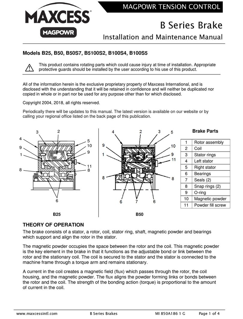
2.2 Functional Description
The COMBISTOP type 38 brake is an electromagnetically actuated dual-surface
spring-applied brake for dry running.
The braking force is generated in de-energised state by pressure springs which press
the armature and the lining against the friction surfaces. The lining is twist-proof but
can be axially moved while connected to the shaft.
After applying the nominal DC voltage, the coil inside the magnet creates a magnetic
field which attracts the armature against the spring force. In this way, the linings are
released and the shaft can rotate freely.
After disconnecting the voltage, the armature is de-energised. The pressure springs
press the armature against the linings which generate the braking torque on the friction
surfaces. This allows for decelerating downstream elements.
Using the optional hand release, the brake can be manually opened even in the event
of a malfunction (see section "5.1 Actuating the Hand Release").
2.3 Safety Devices
2.3.1 Micro Switch (Option)
A micro switch can be used to monitor the switching state of the armature (brake
open/closed). The user is responsible to connect the electrical equipment and to
evaluate the signals! The drive control must not allow the motor to start until the
armature was attracted by the magnet, i. e., the lining can rotate freely.
For more information on how to install and set the micro switch, refer to section "4.1.4
Micro Switch (Option)".

Transport and Storage
01.09.2011 Rev. 01 COMBISTOP Type 38 Page 10
3 Transport and Storage
The brake is delivered to the customer by a transport company that has been
authorised by the manufacturer.
3.1 Inspections on Acceptance by the Recipient
The brake is delivered to the customer in a cardboard packaging. On arrival at the
customer's premises, the brake needs to be checked for visible transport damages.
Immediately report the transport damages to the transport company and the
manufacturer.
3.2 Notes on Transport
Depending on its design and weight (see section "9.1 Technical Data"), the brake must
be lifted and transported using appropriate lifting devices.
3.3 Packaging
The packaging used to transport and protect the brake is normally made of cardboard.
Note!
Dispose of the packaging material according to the local regulations
and/or make sure that the packaging material is reused in an
environmentally responsible way!
3.4 Storage Instructions for Temporary Storage
If the brake is not installed immediately upon delivery or if the brake is not used in the
meantime, it must be properly stored in a dry place. The brake must be stored
temporarily so that neither dust nor moisture nor corrosive vapours can enter the brake.
Note!
In case of improper storage, no liability is assumed for resulting
damages!

Mounting and Start-up
01.09.2011 Rev. 01 COMBISTOP Type 38 Page 11
4 Mounting and Start-up
4.1 Mounting
Note!
The numbers given in the description below refer to the figure listed in
section "2.1 Overview/Parts List".
4.1.1 Notes on Mounting
Inspections to be Done Prior to Mounting the Brake
Before mounting the brake, check the following:
–compliance of the ordered voltage and performance data with the type plate data
–no damage to the brake or contamination by foreign particles in the area of
operation or in the air gap of the brake
–Provide a suitable second friction surface. Even friction surfaces made of cast iron
or steel are best suited for use. The surface roughness RZshould not exceed 25
μm. Avoid sharp-edged interruptions in the friction surface. If such a surface is not
available, a friction disc or a flange (available as an accessory) can be used.
–The friction surfaces must be free from grease and oil.
–Air humidity, aggressive vapours/liquids or the like may lead to corrosion and cause
the lining to stick. In this case, the user needs to provide appropriate measures!
–The brake must be de-energised when being mounted.
Instructions to Be Observed during Mounting
During mounting, please observe the following notes/instructions:
–The friction surfaces of the brake must not come into contact with oil, grease, water
or other fluids. Any contamination will result in loss of torque.
–Never use aggressive fluids (for example, cleaning agents) or the like to clean the
brake.
–When mounting the hub and the magnetic system, the teeth of the hub and the
lining must not be damaged.
–The lining must be easily movable on the hub.
–The movement of the armature must not be impeded by the ingress of foreign
particles into the air gap. If necessary, dust protection rings (accessories) are to be
used or other protective measures are to be taken.
–The eccentricity of the mounting hole circle relative to the shaft end must not exceed
the following values: Size 02: 0.2 mm; Size 03 to 06: 0.4 mm;
Size 07 to 10: 0.5 mm; Size 11: 0.6 mm.

Mounting and Start-up
01.09.2011 Rev. 01 COMBISTOP Type 38 Page 12
–The angular deviation of the mounting surface relative to the shaft must not exceed
the following values: Size 02 to 03: 0.04 mm; Size 04 to 05: 0.05 mm;
Size 06 to 07: 0.06 mm; Size 08 to 10: 0.08 mm; Size 11: 0.1 mm (in relation to the
mounting hole diameter).
4.1.2 Mounting the Brake
The following overview shows a detail of the fully assembled brake depending on its
design; i. e., with flange or with friction disc:
Brake with Flange and Dust Protection
Ring
Brake with Friction Disc and Dust
Protection Ring
If necessary, install the optional components such as friction disc, flange and dust
protection ring (4, 5 and 7) on the motor bearing assembly.
Step 1:
Installing the Hub
Install the hub (2) on the motor shaft,
then secure the hub on the motor shaft
axially.
The hub and the linings must not be
damaged!

Mounting and Start-up
01.09.2011 Rev. 01 COMBISTOP Type 38 Page 13
Make sure that the hub cannot run
against the second friction surface.
Taking into account the axial play of the
shaft, a distance of 0.5 mm to 1 mm is
recommended.
Step 2:
Mounting the Lining
Slide the lining (3) onto the hub.
While doing so, be careful not to
damage the lining by misaligned or
tilted positioning.
The lining must be easily movable on
the hub!
Step 3:
Mounting the Magnetic System
Slide the fully assembled magnetic
system (1) over the hub and the lining.
While doing so, make sure that the
lining is easily movable. Use three
socket head screws to fasten the
magnetic system. In this process, use a
feeler gauge to check the air gap X (in
de-energised state) (see figure below).
Notes on Socket Head Screws!
To attach the magnetic system, we recommend using socket head
screws of property class 8.8 which should be tightened with the
tightening torques recommended by the manufacturer.

Mounting and Start-up
01.09.2011 Rev. 01 COMBISTOP Type 38 Page 14
Checking the Air Gap X
Use a feeler gauge (F) to check the air
gap X as described in section "7.3.1
Checking the Air Gap". If the air gap X
is larger than Xn, the air gap must be
readjusted. To this end, follow the
instructions in section "7.3.2
Readjusting the Air Gap".
Size
02
03
04
05
06
07
08
09
10
11
Design
N/H
N/H
N/H
N/H
N/H
N/H
N/H
N/H
N/H
N/H
Nominal air gap
X
[mm]
0.2
0.2
0.2
0.2
0.3
0.3
0.4
0.4
0.5
0.6
For more information on how to check the air gap which becomes larger as a result of
wear and how to readjust the air gap, refer to section "7.3 Maintenance Work".
4.1.3 Mounting the Hand Release (Option)
This section describes the subsequent mounting of the optional hand release to the
brake.
Note!
The type of hand release attachment to the brake may vary depending
on the ordered design (N/H) and size of the brake.
For information on the components (items 1 to 10) to be used for
installation, refer to the exploded assembly drawing and the table on
the next page.

Mounting and Start-up
01.09.2011 Rev. 01 COMBISTOP Type 38 Page 15
Size
02
03
04
05
05
06
06
07
08
09
10
Design
N/H
N/H
N/H
N
H
N
H
N/H
N/H
N/H
N/H
Item
Designation
1
hand release
bracket
1x
1x
1x
1x
1x
1x
1x
1x
1x
1x
1x
2
handle
1x
1x
1x
1x
1x
1x
1x
1x
1x
1x
1x
3
hexagon head
screw
2x
2x
2x
2x
2x
2x
2x
2x
4
pressure spring
2x
2x
2x
2x
2x
2x
2x
2x
2x
2x
2x
5
locking plate
2x
2x
2x
2x
2x
6
disc
2x
2x
2x
2x
2x
2x
7
disc
2x
2x
2x
2x
2x
2x
2x
2x
8
hexagon nut
2x
2x
2x
2x
2x
2x
2x
2x
2x
2x
2x
9
coiled spring pin
2x
2x
2x
10
eye bolt
2x
2x
2x
'm'
adjustment
dimension [mm]
0.8
1.0
1.4
1.5
1.5
1.8
1.8
2.0
2.0
2.3
2.7
Other manuals for COMBISTOP 38
3
Table of contents
Other KEBCO Spring Applied Brake manuals