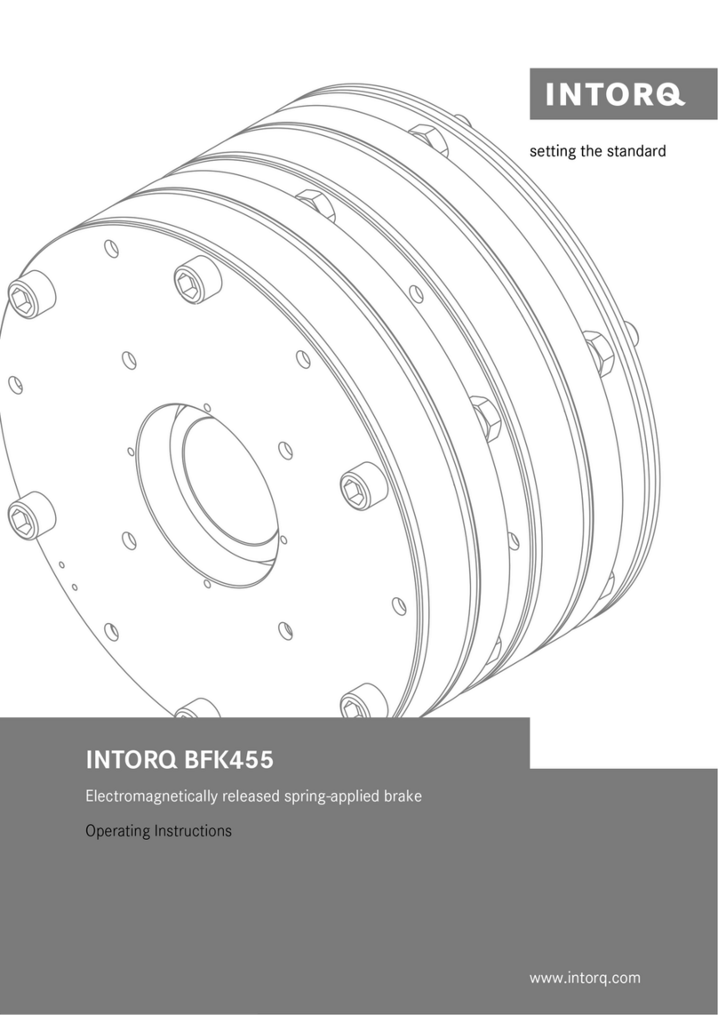
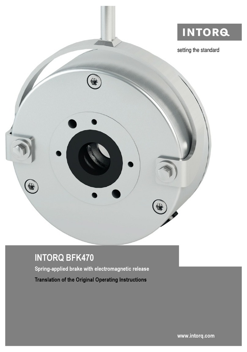
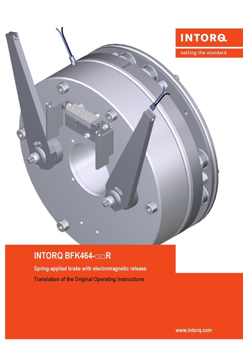
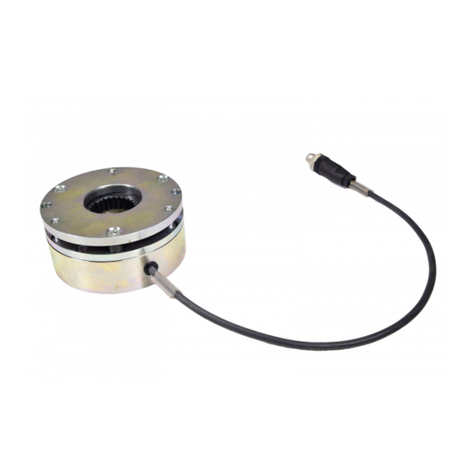
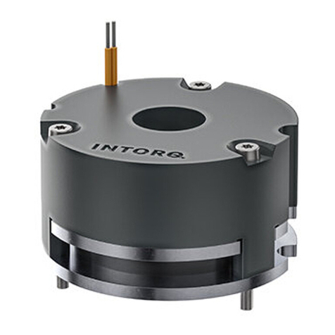
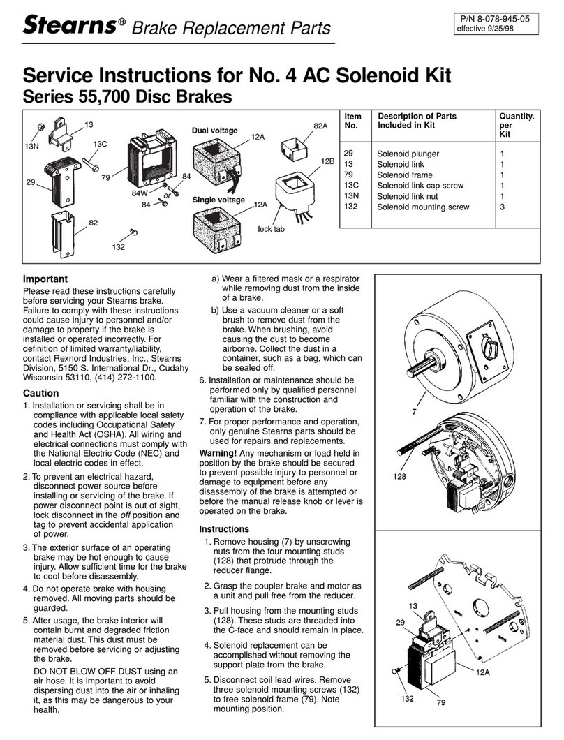
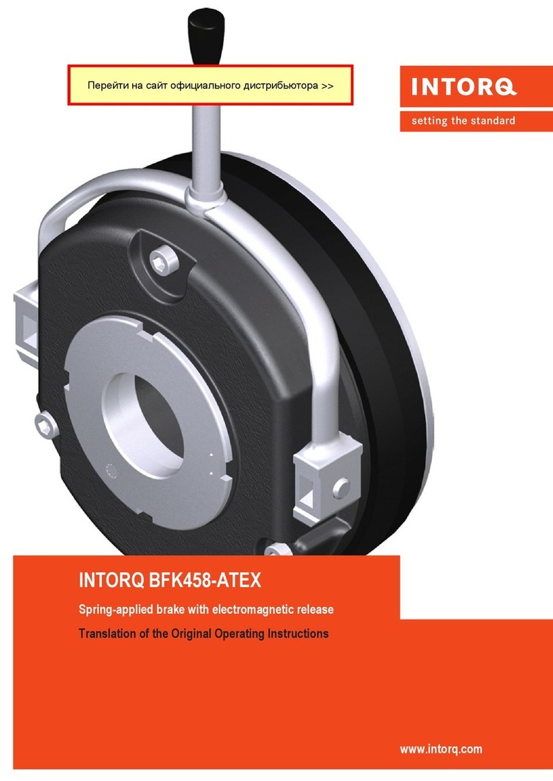
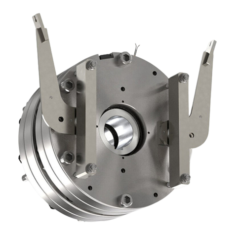
INTORQ BFK468 User manual

INTORQ BFK468
j
setting the standard
Operating Instructions
www.intorq.com
Electromagnetically released spring−applied brake

j| BA 14.0190 | 11/2012
2
This documentation applies to ...
BFK468
BFK46825−002.iso/dms
Product key
Product key INTORQ B FK LLL −LL L
Legend for INTORQ BFK468 product key
Product group Brakes
Product family Spring−applied brake
Type 468
Size 18, 20, 25, 31
Design E − adjustable (brake torque can be reduced via adjuster nut)
N − not adjustable
Not coded: Supply voltage, hub bore, options

j| BA 14.0190 | 11/2012
i
3
Identification
Package label Example
Manufacturer Bar code
Type (see product key) Type No.
Name Rated torque Quantity per box
Release/holding voltage Release/holding power Packing date
Additional information CE designation
BFK458−002.iso/dms
Nameplate Example
Manufacturer CE designation
Type (see product key)
Rated voltage Rated power Hub diameter
Type No. Rated torque Production date
BFK468−001.iso/dms
Document history
Material number Version Description
13190474 1.0 01/2007 TD09 First edition
33002357 2.0 11/2012 TD09 Complete revision
0Fig. 0Tab. 0

Contentsi
j| BA 14.0190 | 11/2012
4
1 Preface and general information 5. . . . . . . . . . . . . . . . . . . . . . . . . . . . . . . . . . . . . . .
1.1 About these Operating Instructions 5. . . . . . . . . . . . . . . . . . . . . . . . . . . . . . . . . . .
1.2 Terminology used 5. . . . . . . . . . . . . . . . . . . . . . . . . . . . . . . . . . . . . . . . . . . . . . . . .
1.3 Conventions used 5. . . . . . . . . . . . . . . . . . . . . . . . . . . . . . . . . . . . . . . . . . . . . . . . .
1.4 Abbreviations used 6. . . . . . . . . . . . . . . . . . . . . . . . . . . . . . . . . . . . . . . . . . . . . . . .
1.5 Notes used 7. . . . . . . . . . . . . . . . . . . . . . . . . . . . . . . . . . . . . . . . . . . . . . . . . . . . . .
1.6 Scope of supply 8. . . . . . . . . . . . . . . . . . . . . . . . . . . . . . . . . . . . . . . . . . . . . . . . . .
1.7 Disposal 8. . . . . . . . . . . . . . . . . . . . . . . . . . . . . . . . . . . . . . . . . . . . . . . . . . . . . . . .
1.8 Drive systems 8. . . . . . . . . . . . . . . . . . . . . . . . . . . . . . . . . . . . . . . . . . . . . . . . . . . .
1.9 Legal regulations 9. . . . . . . . . . . . . . . . . . . . . . . . . . . . . . . . . . . . . . . . . . . . . . . . .
2 Safety instructions 10. . . . . . . . . . . . . . . . . . . . . . . . . . . . . . . . . . . . . . . . . . . . . . . . . . .
2.1 General safety information 10. . . . . . . . . . . . . . . . . . . . . . . . . . . . . . . . . . . . . . . . . .
2.2 Application as directed 11. . . . . . . . . . . . . . . . . . . . . . . . . . . . . . . . . . . . . . . . . . . .
3 Technical data 12. . . . . . . . . . . . . . . . . . . . . . . . . . . . . . . . . . . . . . . . . . . . . . . . . . . . . . .
3.1 Product description 12. . . . . . . . . . . . . . . . . . . . . . . . . . . . . . . . . . . . . . . . . . . . . . .
3.2 Brake torques 15. . . . . . . . . . . . . . . . . . . . . . . . . . . . . . . . . . . . . . . . . . . . . . . . . . .
3.3 Rated data 16. . . . . . . . . . . . . . . . . . . . . . . . . . . . . . . . . . . . . . . . . . . . . . . . . . . . . .
3.4 Operating times 18. . . . . . . . . . . . . . . . . . . . . . . . . . . . . . . . . . . . . . . . . . . . . . . . . .
3.5 Operating frequency / friction work 19. . . . . . . . . . . . . . . . . . . . . . . . . . . . . . . . . .
3.6 Emission 20. . . . . . . . . . . . . . . . . . . . . . . . . . . . . . . . . . . . . . . . . . . . . . . . . . . . . . .
4 Mechanical installation 21. . . . . . . . . . . . . . . . . . . . . . . . . . . . . . . . . . . . . . . . . . . . . . . .
4.1 Necessary tools 21. . . . . . . . . . . . . . . . . . . . . . . . . . . . . . . . . . . . . . . . . . . . . . . . . .
4.2 Mounting 22. . . . . . . . . . . . . . . . . . . . . . . . . . . . . . . . . . . . . . . . . . . . . . . . . . . . . . .
4.3 Installation 22. . . . . . . . . . . . . . . . . . . . . . . . . . . . . . . . . . . . . . . . . . . . . . . . . . . . . .
5 Electrical installation 29. . . . . . . . . . . . . . . . . . . . . . . . . . . . . . . . . . . . . . . . . . . . . . . . .
5.1 Bridge/half−wave rectifiers (option) 29. . . . . . . . . . . . . . . . . . . . . . . . . . . . . . . . . . .
5.2 Electrical connection 31. . . . . . . . . . . . . . . . . . . . . . . . . . . . . . . . . . . . . . . . . . . . . .
6 Commissioning and operation 34. . . . . . . . . . . . . . . . . . . . . . . . . . . . . . . . . . . . . . . . . .
6.1 Functional test 34. . . . . . . . . . . . . . . . . . . . . . . . . . . . . . . . . . . . . . . . . . . . . . . . . . .
6.2 Reducing the brake torque 38. . . . . . . . . . . . . . . . . . . . . . . . . . . . . . . . . . . . . . . . .
6.3 During operation 39. . . . . . . . . . . . . . . . . . . . . . . . . . . . . . . . . . . . . . . . . . . . . . . . .
7 Maintenance/repair 40. . . . . . . . . . . . . . . . . . . . . . . . . . . . . . . . . . . . . . . . . . . . . . . . . .
7.1 Wear of spring−applied brakes 40. . . . . . . . . . . . . . . . . . . . . . . . . . . . . . . . . . . . . . .
7.2 Inspections 41. . . . . . . . . . . . . . . . . . . . . . . . . . . . . . . . . . . . . . . . . . . . . . . . . . . . . .
7.3 Maintenance operations 42. . . . . . . . . . . . . . . . . . . . . . . . . . . . . . . . . . . . . . . . . . . .
7.4 Spare−parts list 44. . . . . . . . . . . . . . . . . . . . . . . . . . . . . . . . . . . . . . . . . . . . . . . . . .
7.5 Spare parts order 45. . . . . . . . . . . . . . . . . . . . . . . . . . . . . . . . . . . . . . . . . . . . . . . .
8 Troubleshooting and fault elimination 46. . . . . . . . . . . . . . . . . . . . . . . . . . . . . . . . . . .
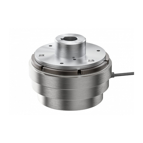
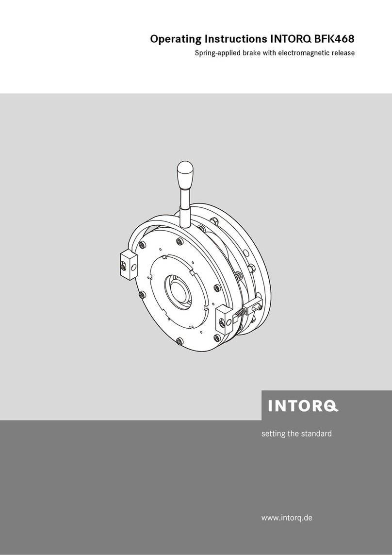
Preface and general information1
i
j| BA 14.0190 | 11/2012
5
1 Preface and general information
1.1 About these Operating Instructions
| These Operating Instructions will help you to work safely on and with the
spring−applied brake with electromagnetic release. They contain safety instructions
that must be followed.
| All persons working on or with the electromagnetically released spring−applied brakes
must have the Operating Instructions available and observe the information and notes
relevant for them.
| The Operating Instructions must always be in a complete and perfectly readable
condition.
1.2 Terminology used
Term In the following text used for
Spring−applied brake Spring−applied brake with electromagnetic release
Drive system Drive systems with spring−applied brakes and other drive
components
1.3 Conventions used
This documentation uses the following conventions to distinguish different types of
information:
Spelling of numbers Decimal separator Point The decimal point is always used.
For example: 1234.56
Symbols Page reference Reference to another page with additional information
For example: 16 = see page 16
Document reference Reference to another documentation with additional
information
For example: Operating instructions
Wildcard Wildcard for options, selections
For example: BFK458− = BFK458−10

Preface and general information1
j| BA 14.0190 | 11/2012
6
1.4 Abbreviations used
Abbreviation Unit Name
I [A] Current
IN[A] Rated current at 20 °C and rated voltage
MA[Nm] Tightening torque of the fixing screws
MN[Nm] Characteristic torque of the brake / clutch
nmax [r/min] Maximum speed during the slipping time t3
PN[W] Rated coil power at rated voltage and at 20 °C
Q [J] Quantity of heat/energy
QE[J] Maximally permissible friction energy for one−time switching
QR[J] Braking energy, friction energy
QSmax [J] Maximally permissible friction energy for cyclic switching
RN[Ohm] Rated coil resistance at 20 °C
Sh[1/h] Operating frequency, i.e. the number of periodical switching opera-
tions
Shue [1/h] Transition operating frequency for thermal characteristic of the
brake / clutch
Shmax [1/h] Maximally permissible operating frequency, depending on the fric-
tion energy per switching operation
sL[mm] Air gap, i.e. lift of the armature plate while the brake is switched, or
lift of the armature part when the clutch is switched
sLN [mm] Rated air gap
sLmin [mm] Minimum air gap
sLmax [mm] Maximum air gap
t1[s] Engagement time, i.e. sum of the delay time and the braking torque
exit time t1= t11 + t12
t2[s] Disengagement time, i.e. time between switching the stator and
reaching 0.1 MK
t11 [s] Slipping time, i.e. engagement time of the brake (after t11) until
standstill
t11 [m] Delay during engagement, i.e. time from switching off the supply
voltage to the beginning of the torque rise
t12 [m] Rise time of the braking torque, i.e. time from the start of the torque
rise until reaching the braking torque
U [V] Voltage
UN[V] Rated coil voltage

Preface and general information1
i
j| BA 14.0190 | 11/2012
7
1.5 Notes used
The following pictographs and signal words are used in this documentation to indicate dangers
and important information:
Safety instructions
Structure of safety instructions:
Danger!
Characterises the type and severity of danger
Note
Describes the danger
Possible consequences:
| List of possible consequences if the safety instructions are disregarded.
Protective measure:
| List of protective measures to avoid the danger.
Pictograph and signal word Meaning
Danger!
Danger of personal injury through dangerous electrical voltage
Reference to an imminent danger that may result in death or serious
personal injury if the corresponding measures are not taken.
Danger!
Danger of personal injury through a general source of danger
Reference to an imminent danger that may result in death or serious
personal injury if the corresponding measures are not taken.
Stop!
Danger of property damage
Reference to a possible danger that may result in property damage if the
corresponding measures are not taken.
Application notes
Pictograph and signal word Meaning
Note! Important note to ensure troublefree operation
Tip! Useful tip for simple handling
Reference to another documentation

Preface and general information1
j| BA 14.0190 | 11/2012
8
1.6 Scope of supply
After receipt of the delivery, check immediately whether it corresponds to the accompanying
papers. INTORQ does not grant any warranty for deficiencies claimed subsequently.
| Claim visible transport damage immediately to the forwarder.
| Claim visible deficiencies / incompleteness immediately to INTORQ GmbH & Co.KG.
1.7 Disposal
The spring−applied brake consists of different types of material.
| Recycle metals and plastics.
| Ensure professional disposal of assembled PCBs according to applicable
environmental regulations.
1.8 Drive systems
Labelling
Drive systems and components are unambiguously designated by the indications on the
nameplate.
Manufacturer: INTORQ GmbH & Co KG, Wülmser Weg 5, D−31855 Aerzen
| The spring−applied INTORQ brakeis also delivered in single modules and individually
combined to its modular design. The data − package labels, nameplate, and type code
in particular − apply to one complete stator.
| If single modules are delivered, the labelling is missing.

Preface and general information1
i
j| BA 14.0190 | 11/2012
9
1.9 Legal regulations
Liability
| The information, data and notes in this documentation met the state of the art at the
time of printing. Claims referring to products which have already been supplied cannot
be derived from the information, illustrations and descriptions.
| We do not accept any liability for damage and operating interference caused by:
– inappropriate use
– unauthorised modifications to the product
– improper working on and with the product
– operating faults
– disregarding the documentation
Warranty
| Terms of warranty: see terms of sale and delivery of INTORQ GmbH & Co. KG.
| Warranty claims must be made to INTORQ immediately after detecting defects or
faults.
| The warranty is void in all cases where liability claims cannot be made.

Safety instructions2
j| BA 14.0190 | 11/2012
10
2 Safety instructions
2.1 General safety information
| INTORQ components ...
– ... must only be applied as directed.
– ... must not be commissioned if they are noticeably damaged.
– ... must not be technically modified.
– ... must not be commissioned if they are mounted incompletely.
– ... must not be operated without the required covers.
– ... can hold live as well as moving or rotary parts during operation according to their
degree of protection. Surfaces may be hot.
| For INTORQ components ...
– ... the documentation must always be kept at the installation site.
– ... only permitted accessories are allowed to be used.
– ... only original spare parts of the manufacturer are allowed to be used.
| All specifications of the corresponding enclosed documentation must be observed.
This is vital for a safe and trouble−free operation and for achieving the specified product
features.
| Only qualified, skilled personnel are permitted to work on and with INTORQ
components.
In accordance with IEC 60364 or CENELEC HD 384, qualified, skilled personnel are
persons ...
– ... who are familiar with the installation, mounting, commissioning, and operation of
the product.
– ... who have the qualifications necessary for their occupation.
– ... who know and apply all regulations for the prevention of accidents, directives, and
laws relevant on site.
| Risk of burns!
– Surfaces may be hot during operation! Provide for protection against accidental
contact.
| Risk of injury due to a rotating shaft!
– Wait until the motor is at standstill before you start working on the motor.
| The friction lining and the friction surfaces must by no means have contact to oil or
grease since even small amounts reduce the brake torque considerably.
| The brake is designed for operation under the environmental conditions that apply to
IP54. Because of the numerous possibilities of using the brake, it is however necessary
to check the functionality of all mechanical components under the corresponding
operating conditions.

Safety instructions2
i
j| BA 14.0190 | 11/2012
11
2.2 Application as directed
| INTORQ components ...
– ... are intended for use in machinery and systems.
– ... must only be used for the purposes ordered and confirmed.
– ... must only be operated under the ambient conditions prescribed in these
Operating Instructions.
– ... must not be operated beyond their corresponding power limits.
Any other use shall be deemed inappropriate!
Possible applications of the INTORQ spring−applied brake
| Humidity: no restrictions
– In case of formation of condensed water and moisture: provide for appropriate
ventilation to ensure that all components will dry quickly.
| Ambient temperature:
– −20 °C to +40 °C (standard)
| At high humidity and low temperature:
– Take measures to protect armature plate and rotor from freezing.
| Protect electrical connections against contact.

Technical data3
j| BA 14.0190 | 11/2012
12
3 Technical data
3.1 Product description
BFK46820−003.iso/dms
Fig. 1 Design of the BFK468 spring−applied brake: basic module E (complete stator) + rotor + hub +
flange
1 Complete stator 3 Complete rotor 6 Flange
1.2 Compression springs 4 Hub 9 Sleeve bolts
2 Armature plate 5 Shaft 31 Torque adjustment ring
KL 46820−001.iso/dms
Fig. 2 Design of the BFK468 spring−applied brake: basic module N (complete stator) + rotor + hub +
flange
1 Complete stator 3 Complete rotor 6 Flange
1.2 Compression springs 4 Hub 9 Sleeve bolts
2 Armature plate 5 Shaft

Technical data3
i
j| BA 14.0190 | 11/2012
13
3.1.1 General information
The spring−applied brake is designed for the conversion of mechanical work and kinetic energy
into heat. Due to the static brake torque, the brake can hold loads without speed difference.
Emergency braking is possible at high speed. The more friction work, the higher the wear.
(Operating speeds 16)
The BFK468− spring−applied brake is a single−disk brake with two friction surfaces.
Several compression springs (1.2) generate the braking torque by friction locking. The brake
is released electromagnetically by a reduction of the holding current via an INTORQ bridge
half−wave rectifier.
The stator (1) is designed to be of thermal class F. The limit temperature of the coils is 155°C.
3.1.2 Braking
During braking the rotor (3) axially slidable on the hub (4) is pressed against the friction
surface by the inner and outer springs (1.2) via the armature plate. The asbestos−free
friction linings ensure a high braking torque and low wear. The braking torque transmission
between hub (4) and rotor (3) is effected by means of toothing.
3.1.3 Brake release
In braked state, there is an air gap "sL" between the stator (1.1) and the armature plate (2).
To release the brake, the coil of the stator (1.1) is excited with the DC voltage provided. The
magnetic force generated attracts the armature plate (2) towards the stator (1.1) against the
spring force. The rotor (3) is then released and can rotate freely.
3.1.4 Brake torque reduction
For basic module E (adjustable), the spring force and thus the brake torque can be reduced
by unscrewing the adjuster nut (8), (38).
3.1.5 Manual release (optional for sizes 18 to 25)
The manual release is optionally available for short−term releases when no voltage is applied.
The manual release can be retrofitted.

Technical data3
j| BA 14.0190 | 11/2012
14
3.1.6 Microswitch (optional)
The manufacturer offers the microswitch for air−gap or wear monitoring. The user must provide
the corresponding electrical connection (31et seqq.).
When air−gap monitoring, the motor does not start before the brake has been released. With
this set−up, all possible faults are monitored. For example, in the event of defective rectifiers,
interrupted connection cables, defective coils, or excessive air gaps the motor will not start.
When checking the wear, no current will be applied to the brake and the motor if the air gap
is too large.
3.1.7 Encapsulated design (optional)
This design not only avoids the penetration of spray water and dust, but also the spreading
of abrasion particles outside the brake. This is achieved by:
| a cover seal over the armature plate and rotor,
| a cover in the adjuster nut,
| a shaft seal in the adjuster nut for continuous shafts (option).

Technical data3
i
j| BA 14.0190 | 11/2012
15
3.2 Brake torques
Stop!
Please observe that engagement times and disengagement times change
depending on the brake torque.
Size 18 20 25 31
Characterist
ic torque
Torque
reduction E
per detent
position
Characterist
ic torque
Torque
reduction E
per detent
position
Characterist
ic torque
Torque
reduction E
per detent
position
Characterist
ic torque
[Nm] [Nm] [Nm] [Nm] [Nm] [Nm] [Nm]
230 N
Rated torques [Nm],
relating to the
relative speed Dn =
100 rpm
Depending on the
rated torque (spring
assembly), the angle
of rotation for the
braking torque
reduction can be
60°, 120° or 180°
for basic module E.
100 N/E 6.4 170 N/E 19.8 260 N/E 16.5
115 N/E 6.4 200 N/E 19.8 300 N/E 8.2 720 N
130 N/E 6.4 230 N/E 9.9 350 N/E 8.2 960 N
150 N/E 3.2 260 N/E 9.9 400 N/E 8.2 1200 N
165 N/E 3.2 300 N/E 19.8 445 N/E 16.5 1440 N
185 N/E 6.4 345 N/E 19.8 490 N/E 8.2 1680 N
200 N/E 6.4 400 N/E 19.8 520 N/E 16.5 1920 N
235 N/E 6.4 440 N/E 19.8 600 N/E 16.5 2160 N
265 N/E 6.4 480 N/E 19.8 700 N/E 16.5 2400 N
300 N/E 6.4 520 N/E 19.8 800 N/E 16.5
Tab. 1 N.....Brake torque for module N (without torque adjustment ring)
E......Brake torque for module E (with torque adjustment ring)
Holding brake with emergency stop operation (sLmax. approx. 2.0 x sLN)
Service brake (sLmax. approx. 4.0 x sLN)
Standard braking torque
3.2.1 Basic module E, brake torque reduction
For basic module E, the braking torque can be reduced by means of the torque adjustment
ring in the stator. The torque adjustment ring must only be screwed out up to the maximum
projection "hEmax.", 16 and 38.

Technical data3
j| BA 14.0190 | 11/2012
16
3.2.2 Brake torques depending on the speed and permissible limit speeds
Type Rated torque at
Dn = 100 rpm
Braking torque at Dn0[rpm] [%] max. speed
Dn0max. with
horizontal
mounting position
[%] 1500 3000 maximum [rpm]
BFK468−18
100
77 70
66
4400
BFK468−20 75 68 3700
BFK468−25 73 66 3000
BFK468−31 69 −−−−− 2300
Tab. 2 Brake torques depending on the speed and permissible limit speeds
3.3 Rated data
Type sLN
+0.1 mm
−0.05 mm
sLmax.
service
brake
sLmax.
holding
brake
Max.
adjustment,
permissible
wear
distance
Rotor thickness Excess
of the torque
adjustment
ring hEmax.
[mm] [mm] [mm] [mm] min. 1) [mm] max. [mm] [mm]
BFK468−18
0 4
1 0 0.6 3.0 10.0 13.0 15
BFK468−20
1 25
4.0 12.0 16.0 17
BFK468−25
0 5
0.75 4.5 15.5 20.0 19.5
BFK468−31 1.5 1.0 3.0 15.0 18.0 −−−−
1) The friction lining is designed such that the brake can be adjusted at least 5 times.
Type Pitch circle Tightening torque Weight
of complete stator
[mm] Thread Screws [Nm] Complete
lever [Nm]
[kg]
BFK468−18 196 6 x M8 36.1 23 13.4
BFK468−20 230
6 x M10 71 40
20.0
BFK468−25 278 31.0
BFK468−31 360 8 x M16 302 −−−−− 55.1
Tab. 3 Characteristics of BFK468 spring−applied brake

Technical data3
i
j| BA 14.0190 | 11/2012
17
Type Electrical power P 1) Release voltage/holding voltage
U
Coil resistance RN ±8 %
[W] [V] [W]
BFK468−18 85 / 340
205 / 103 123.5
360 / 180 381.5
BFK468−20 100 / 408
205 / 103 106.1
360 / 180 317.6
BFK468−25 132 / 528
205 / 103 79.6
360 / 180 245.5
BFK468−31 230 / 920 360 / 180 140.9
1) Coil power at 20 _C
Tab. 4 Coil voltage/coil resistance of BFK468
3.3.1 Project planning notes
| The brakes are dimensioned in such a way that the given characteristic torques are
reached safely after a short run−in process.
| Due to the fluctuating properties of the organic friction linings used and the alternating
environmental conditions, deviations of the given braking torques may occur. These
must be considered by corresponding safety measures in the dimensioning process.
Especially with humidity and alternating temperatures, an increased breakaway torque
may occur after a long downtime.
| Check the braking torque if the brake is inserted on the customer’s friction surfaces.
| If the brake is used as a pure holding brake without dynamic load, the friction lining
must be reactivated regularly.

Technical data3
j| BA 14.0190 | 11/2012
18
3.4 Operating times
BFKXXX−011.iso/dms
Fig. 3 Operating times of the spring−applied brakes
t1Engagement time t11 Reaction delay during engagement
t2Disengagement time (up to M = 0.1 Mr)t
12 Rise time of the brake torque
MKCharacteristic torque U Voltage
Type Rated torque at
Dn = 100 rpm
Max. permissible
friction work per
operation only
Transition
operating
frequency
Operating times [ms] at sLN
MK1) QEshue DC engagement Disengage
[Nm] [J] [h−1] t11 t12 t1t2
BFK468−18 150 60000 20 26 30 56 70
BFK468−20 260 80000 19 102 112 168 106
BFK468−25 400 120000 15 60 135 197 120
BFK468−31 1200 300000 13 65 133 198 250
1) Minimum braking torque when all components are run in
Tab. 5 Switching energy − operating frequency − operating times
Engagement time
The transition from brake−torque free state to holding braking torque is not free of time lags.
A braking torque reduction via the torque adjustment ring prolongs the engagement time and
reduces the disengagement time.
| The engagement times are valid for DC switchingwith a spark suppressor.
– Spark suppressors are available for the rated voltages.
– Connect the spark suppressors in parallel to the contact. If this is not admissible for
safety reasons, e.g. with hoists and lifts, the spark suppressor can also be
connected in parallel to the brake coil.
– Circuit proposals: 31, Fig. 15
| The engagement times are approx. 5 times longer with AC switching.
– Connection: 31, Fig. 14

Technical data3
i
j| BA 14.0190 | 11/2012
19
Disengagement time
The disengagement time is the same for DC and AC switching.
3.5 Friction work / operating frequency
110 100 1000 10000
100
1000
10000
100000
1000000
Q [J]
S [h ]
h-1
31
25
20
18
A
B
BFK468−003.des/dms
Fig. 4 Switching energy as a function of the operating frequency
Switching energy Q Operating frequency sh
Shmax +*Shue
lnǒ1*QR
QEǓQsmax +QEǒ1*e
*Shue
ShǓ
The permissible operating frequency "Shmax" depends on the heat quantity "QR" (see Fig. 4).
If the operating frequency "Sh" is given, the permissible heat quantity "Qsmax" can be
calculated.
With high speed and friction work, the wear increases strongly, because very high
temperatures occur at the friction faces for a short time.

Technical data3
j| BA 14.0190 | 11/2012
20
3.6 Emission
Electromagnetic compatibility
Note!
The user must ensure compliance with EMC Directive 2004/108/EC using
appropriate controls and switching devices.
If an INTORQ rectifier is used for the DC switching of the spring−applied brake and if the
operating frequency exceeds five switching operations per minute, the use of a mains filter
is required.
If the spring−applied brake uses a rectifier of another manufacturer for the switching, it
may become necessary to connect a spark suppressor in parallel with the AC voltage.
Spark suppressors are available on request, depending on the coil voltage.
Heat
Since the brake converts kinetic energy as well as mechanical and electrical energy into heat,
the surface temperature varies considerably, depending on the operating conditions and
possible heat dissipation. Under unfavourable conditions, the surface temperature can reach
130 _C.
Geräusche
Das Schaltgeräusch beim Verknüpfen und Trennen ist unterschiedlich groß. Einflussgrößen
sind Lüftweg, Bremsmoment und Bremsengröße.
Je nach Eigenschwingung im eingebauten Zustand, Betriebsbedingungen und Zustand der
Reibflächen kann Quietschen während des Abbremsvorganges auftreten.
Others
The abrasion of the friction parts produces dust.
In case of high load, the friction face will become so hot that odours may occur.
Other manuals for BFK468
1
Table of contents
Other INTORQ Spring Applied Brake manuals

INTORQ
INTORQ BFK557 Quick guide

INTORQ
INTORQ BFK471-25 Quick guide

INTORQ
INTORQ BFK464-R Series Quick guide

INTORQ
INTORQ BFK455 User manual

INTORQ
INTORQ BFK468 User manual

INTORQ
INTORQ BFK470 Series Quick guide

INTORQ
INTORQ BFK455-25 Quick guide

INTORQ
INTORQ BFK457 Series User manual

INTORQ
INTORQ 14.105 Series User manual

INTORQ
INTORQ BFK466-80 User manual