Orange/green CAN H input (input wire), (thinner wire diameter)
Orange/brown CAN L input (input wire), (thinner wire diameter)
Orange/black (+) trunk open sensing. Connect the wire to the wire of trunk
opening motor on which +12V pulse appears when unlocking. When unlocking, car
alarm automatically misses the trunk contact, ultrasonic and additional sensor. After
closing the trunk, contact and sensors are guarded again after 4 seconds.
Brown/blue - NO contact of locking relay
Blue/white - COM contact of locking relay
Orange/blue - NC contact of locking relay
Brown/green - NO contact of locking relay
Green/white - COM contact of locking relay
Orange/green - NC contact of locking relay
CAUTION: In case, that outputs for central locking not working properly or not
working at all, check setting of function F10, if car alarm is not
set to TS 50 mode!
CONNECTOR CN3 (14PIN) - EASY CAN MODULE CONNECTION
Connector for connection of EASY CAN module. By connecting the module, you
can obtain informations from the CAN BUS about door and trunk open, closing
and opening of the vehicle via the remote control, turn on the ignition (if these
informations are available on CAN BUS)
CONNECTOR CN4 (2PIN) - ultrasonic sensor connection (red)
Connector for ultrasonic sensor connection (marked with red).
CONNECTOR CN5 (2PIN) - ultrasonic sensor connection (white)
Connector for ultrasonic sensor connection (marked with white).
CONNECTOR CN6 (3PIN) - valet button with LED connection
Connector server for vallet switch connection.
Place LED diode on a good visible place.
CONNECTOR CN7 (3PIN) - dual zone sensor connection
Connector for connection of additional dual zone sensor (LSK2, MWS 2)
8 - ultrasonic sensor sensitivity adjustment
CN9 - connection of car alarm to the PC via programming cable T PROG
II. WIRING DIAGRAM FOR TS 100 MODE
III. CONNECTION OF CENTRAL LOCKING INPUTS FOR
TS100 MODE
Direct control of actuators
WARNING: Carefully read following instructions and technical specification
in this manual before installation. The system must be installed and used
only according to this manual. The system is designed for vehicles with 12V
power supply. It has to be connected to 12V output and to the ground. Neither
producer or seller of the system is responsible for damages caused by incorrect
installation, using or operating of this product. Unprofessional operation or
modification of the system can damage the system alone, or the electric system
of the vehicle and leads to warranty loss. For proper working of the system we
recommend the installation to be made by authorized service.
SYSTEM DESCRIPTION
KEETEC TS 100-50 is a car alarm that was created by combining car alarms TS 50
and TS13. It is designed for vehicles with 12 V supply voltage and is used to monitor
the doors, trunk, hood. In case of their disruption, system is reporting alarm by optical
(indicator lights) and audible (siren) signaling. The system includes a built-in ultrasonic
sensor with adjustable sensitivity, that in case of violation of vehicle interior reacts with
alarm. When car alarm is activated, the system automatically blocks the starter circuit
to prevent the unauthorized vehicle start up.
Car alarm can works in two modes. TS 100 and TS 50 and these modes can be set
by function F10. See VI. Programming system functions section for setting
procedure.
TS 100 mode: in this mode, car alarm is controlled by supplied remote controls
or by the original remote controls from vehicle (version with EASY CAN module).
Central locking outputs are used to control the central locking in the car.
TS 50 mode: in this mode, car alarm is controlled by the original remote controls
from vehicle and is connected analogue. Outputs for control of central locking systems,
when you set car alarm to TS 50, changes from outputs to inputs and are used to
analog connect to central locking system, where car alarm gaining information about
activation/deactivation. In the version with EASY CAN module, car alarm obtained
these informations from the CAN BUS. In this mode, you can also use additional
remote controls supplied with car alarm, but can only activate / deactivate the car
alarm, without control the central locking system.
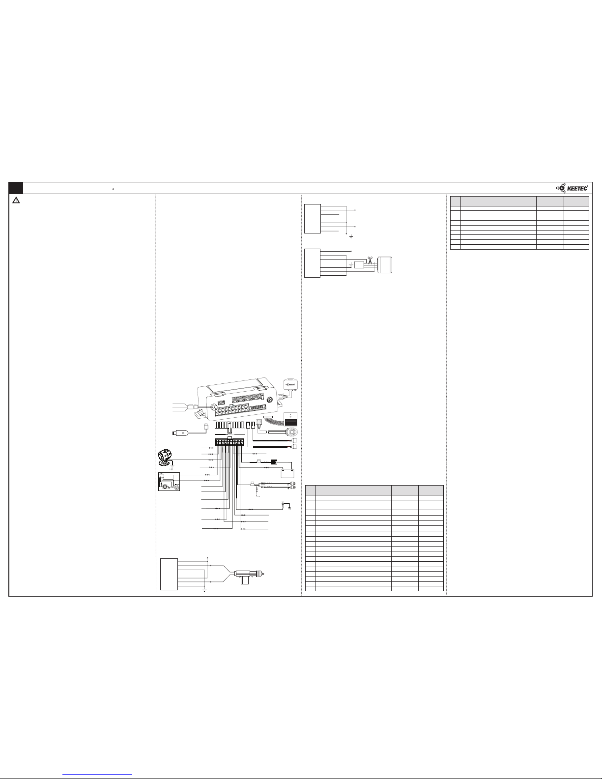
I. SYSTEM INSTALLATION - TS 100 MODE
Remove plastic covers of car dashboard. Find cables for car alarm connection. Use
a digital multimeter to test the function of cables in vehicle, even if you’re sure which
function specific cable does have. After choosing the right cables, disconnect the car
battery and connect the cable harness of car alarm to those cables according to the
attached wiring schemes. Solder and isolate all connections. After finishing the instal-
lation of car alarm, connect the car battery and plug-in a fuse to the fuse cover of the
car alarm. Test correct functionality of the car alarm and the electrical installation of
the car (ignition, direction lights). Mount the plastic covers back on to the dashboard.
Control unit and LED location
Place the control unit from the inner side of protection plastics of the car dashboard.
Fix antenna of the control unit so as not touch the metal parts of the vehicle. Place the
LED diode on a good visible place.
Caution: Outputs of control unit (except for the indicator lights output and central locking
output) have maximum allowed current load of 300mA. To control greater current load, use
additional devices (R1215, IMO 15). Directional lights can load up to 2x5A.
CONNECTOR CN1 (3PIN) - immobilization circuit
Contacts of immobilization relay (NC,NO,COM). Function F29 determine, which
contacts will be connected. NC/COM or NO/COM. Current load up to 30A.
Black/white - COM
Black - NC
Brown - NO
CONNECTOR CN2 (20PIN) - connector of inputs and outputs
Brown
(+/-) - door contacts sensing (input wire)
Brown/black (-) trunk sensing (input wire)
Brown/yellow (-) engine compartment sensing - hood (input wire)
White/red (+/-300mA) - default setting (F17) - siren output (+)
- optional (F17) - horn output (-)
White/blue (+/-) sequential output for optical signalisation (output wire)
Purple (-300mA) output for trunk open
Orange (+10A) output for directional (parking) lights (output wire). If function F9
is set to sequential optical signalisation, this wire serves as input of directional lights
feedback control (see wire diagram)
Yellow (+) ignition +12V (input wire)
Gray (-300mA) - default setting (F21) - PAGER - output is active during alarm
- optional (F21) - immobilization output for motor blocking
Black (-) GND (input wire)
Red (+) power supply +12V (input wire)
Control of central locking system by negative/positive impulse
Connection of pneumatic central locking system
IV. SERVICE MODE
1. Turn ON ignition and press service button 2x within 10 seconds.
2. Turn OFF ignition. If security mode is not active,
siren beeps twice and LED diode shine
permanently. Service mode is now activated. if the security mode is active (function
F19), enter service mode by enter 4 digits PIN code. LED diode starts to flashing
slowly.
- if the LED will flash so many times which is the value of first PIN number, push the
service button one time. LED will start to flash again.
- if the LED will flash so many times which is the value of second PIN number, push the
service button one time. LED will start to flash again.
- if the LED will flash so many times which is the value of third PIN number, push the
service button one time. LED will start to flash again.
- if the LED will flash so many times which is the value of fourth PIN number, push the
service button one time. LED will start to flash again.
if you entered PIN code correctly, siren beeps twice and LED is turn ON permanently.
Service mode is active.
Deactivation of service mode
Turn ON ignition and press the service button 2x within 10 seconds. Turn OFF
ignition. Siren beeps twice and LED diode turns OFF. Service mode is deactivated.
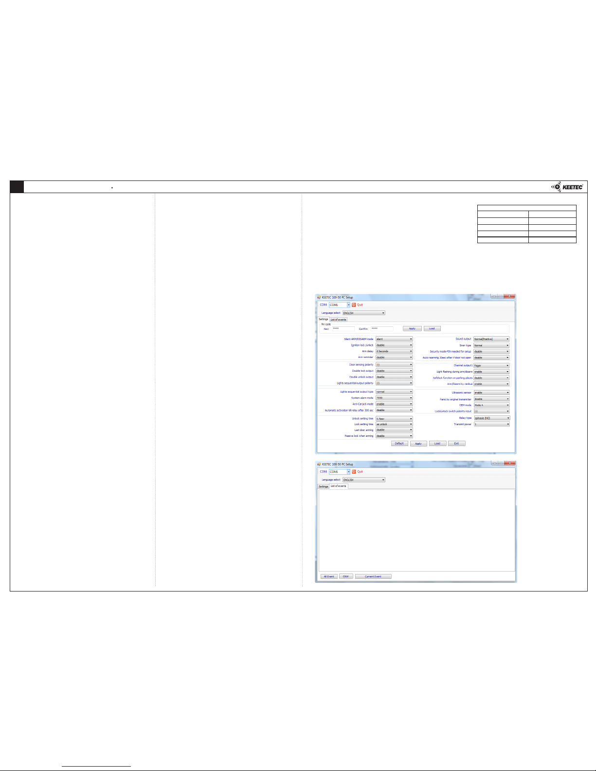
VI. PROGRAMMING SYSTEM FUNCTIONS
When programming functions, follow these steps:
1. Activate service mode and turn ON ignition.
2. Press service button 7x within 10 seconds and turn OFF ignition, LED starts flashing.
3. Press service button so many times which is the value of function you want to
change, within 20 seconds. After each push of service button siren beeps once.
If the number of function is greater than 10, push service button fro 3 seconds. For
example, if you want to set function No.13, press service button for 3 sec., after
release button siren beeps 2 times. Press service button 3 times, after each push
siren beeps once. After turning the ignition ON, siren will sound 1 or 2 times,
depending on which setting was set. If you want to set function No.25, press
the service button for 3 seconds. After releasing the button, siren beeps twice.
Press the button again for 3 seconds. After releasing the button, siren beeps
twice. Press the service button 5 times. Siren beeps after each push of button.
4. Turn ignition ON. Siren will sound 1 or 2 times, depending on which setting was set.
5. You can finish programming by turning the ignition ON and by pressing the button
once, or wait 20 seconds. System is now in service mode.
PROGRAMMING TABLE FOR TS 100 MODE
KEETEC TS 100 CAR ALARM INSTALATION MANUAL 1/2
EN
VI. FUNCTIONS DESCRIPTION
F1. SILENT / LOUD ACTIVATION
PRE-SET: when activate / deactivate the siren does not sound.
ADJUSTABLE: when activate / deactivate the siren beeps
F2. CENTRAL LOCKING SYSTEM LOCK WHEN IGNITION TURNED ON
PRE-SET: central locking system does not lock when ignition turn ON
ADJUSTABLE: when ignition is turned ON, central locking system locks after 20 seconds
Note: when using EASY CAN module, central locking will lock after crossing the
speed of 5 km/h (check in the EASY CAN list of supported vehicles if the vehicle has a
speed signal and set the code 912 of speed output to the switching)
F3. INPUT ACTIVATION DELAY
PRE-SET: inputs are active after 8 seconds after activation of the system
ADJUSTABLE: inputs are active after 40 seconds after activation of the system
F4. SYSTEM ACTIVATION REMINDER
PRE-SET: reminder is turned OFF
ADJUSTABLE: when ignition is OFF and after last door is closed siren sounds 2x after
10 seconds.
F5. DOOR CONTACTS INPUT POLARITY
PRE-SET: input for door contacts react on negative (-) impulse.
ADJUSTABLE: input for door contacts react on positive (+) impulse.
F6. DOUBLE LOCK IMPULSE
PRE-SET: double lock impulse is turned OFF
ADJUSTABLE: double lock impulse is turned ON
F7. DOUBLE UNLOCK IMPULSE
PRE-SET: double unlock impulse is turned OFF
ADJUSTABLE: double unlock impulse is turned ON
F8. SEQUENTIAL OUTPUT POLARITY
PRE-SET: negative polarity on sequential output (- 300 mA)
ADJUSTABLE: positive polarity on sequential output (+ 300 mA)
F9. OPTICAL SIGNALIZATION
PRE-SET: for optical signalisation, power outputs for directional indicators are active
ADJUSTABLE: for optical signalisation, sequential output for directional indicators is
active. In this case, power output for directional lights serves for control of directional
lights function.
F10. CAR ALARM MODE
PRE-SET: TS 50 - car alarm is controlled via original remote control of vehicle
ADJUSTABLE: TS 100 - car alarm is controlled via remote control of car alarm
F11. ANTI CAR-JACK MODE
PRE-SET: function is allowed
ADJUSTABLE: function is prohibited
F12. AUTOMATIC ACTIVATION OF IMMOBILIZATION OUTPUT
PRE-SET: automatic activation is turned OFF
ADJUSTABLE: after turning ignition OFF, immobilization output activate after 5 minutes.
For turn OFF this output, press unlock button on remote control or use emergency
deactivation.
F13. UNLOCKING TIME
PRE-SET: unlock impulse is 0,5 sec.
ADJUSTABLE: unlock impulse is 3,5 sec. (it is not possible to set double unlock impulse)
F14. LOCKING TIME
PRE-SET: same as unlocking time
ADJUSTABLE: 20 seconds
F15. AUTOMATIC ACTIVATION AFTER LAST DOOR CLOSING
PRE-SET: function is prohibited
ADJUSTABLE: after turning OFF ignition and closing last door, system is automatically
activated after 30 seconds.
F16. LOCK OF CENTRAL LOCKING AFTER AUTOMATIC REACTIVATION
PRE-SET: function is prohibited
ADJUSTABLE: after ignition turned OFF and last door is closed, system is automatically
activated after 30 sec. and lock the central locking system
F17. SIREN OUTPUT
PRE-SET: siren output is permanent - siren (+)
ADJUSTABLE: siren output is discontinuous - horn (-)
Prog.
menu
Function Factory settings
1 tone of siren
Adjustable
2 tones of siren
F1
silent / loud activation
silent loud
F2
central locking system lock when ignition turned on
off on
F3
input activation delay
8 sec. 40 sec.
F4
system activation reminder
off on
F5
door contacts input polarity
“-” input “+” input
F6
double lock pulse
off on
F7
double unlock pulse
off on
F8
sequential output polarity
“-” output “+” output
F9
optical signalization
normal sequential
F10 car alarm mode TS 50 TS 100
F11
anti car-jack mode
on off
F12 automatic activation of immobilization output (after 5 min.) off on
F13
unlocking time
0,5 sec. 3,5 sec.
F14
locking time
same as unlocking 20 sec.
F15
automatic activation after last door closing
off on
F16
lock of central locking after automatic reactivation
off on
F17
siren output
siren (+) horn (-)
F18 siren type normal coded
F19
security mode
off on
R
+12V
KEETEC
TS 13
TS 100
brown/blue
blue/white
orange/blue
brown/green
green/white
orange/green
BLUE
GREEN
KEETEC
TS 13
LOCK
UNLOCK
brown/blue
blue/white
orange/blue
brown/green
green/white
orange/green
+12V control by possitive impulse
control by negative impulse
TS 100
+12V
KEETEC
TS 13
brown/blue
blue/white
orange/blue
brown/green
green/white
orange/green
door
lock
TS 100
control
unit
in vehicle
1N5401
CN1
CN2
CN3
CN4 CN5 CN6 CN7
8
CN2
CN3
CN4 CN5
CN6
CN9
CN9
CN7
1N5401
red
black
+12V
GND
directional lights
directional lights
orange
directional lights feedback
control (when using sequential
output)
brown door contact
green/white
orange/black
brown/blue
brown/green
brown/black
orange/blue
orange/brown
orange/green
brown/yellow
ultrasonic sensor
ultrasonic sensor
service button
with LED diode
EASY CAN
CAN BUS module
additional
sensor
T PROG
CAN H (thiner wire diameter)
CAN L (thiner wire diamaeter)
white/red
siren output (+/-)
purple
trunk open (-300mA)
white/blue
orange/green
sequential output (-)
blue/white
gray
immobilizer/pager (-)
yellow
ignition
lock - COM
trunk contact (-)
unlock - COM
lock - NO
iput for trunk open
control (+)
unlock - NO
hood contact
lock - NC
unlock - NC
10A
black/white
black
brown
COM
NC
NO
Prog.
menu
Function Factory settings
1 tone of siren
Adjustable
2 tones of siren
F20
automatic reactivation after 30 seconds
off on
F21 Output No.1 pager imobilizér
F22 optical signalization when activate/deactivate on off
F23 lock check when signal jamming prohibited allowed
F24 CAN BUS activation/deactivation allowed prohibited
F25 ultrasonic sensors allowed prohibited
F26 PANIC alarm by original remote prohibited allowed
F29 immobilization relay NO NC
F30 system reset reset (except F10)