KEETEC TS 8000 User manual

If you want to change the secret CODE, you have to just repeat STEP 1 -2.
Attention: User´s secret code must be registered by user. (Factory setting code
is “1234”).
RPS module installation:
1. Connect 4 pin connector to main control box.
2. lnstallation location: First of all, stick the sticker on the inside the windshield of
the wheel and stick the control module on that sticker.
CONNECTOR CN8 5PIN ANTENNA CONNECTION
The best location for the receiver/antenna is centered on left of the front wind-
shield. The antenna should be mounted horizontally.
Attention: Metallic window tint can also aect range, so this should be a
consideration when determining the mounting location.
Antenna installation:
1. Clean the mounting area with a quality glass cleaner or alcohol to remove any
dirt or residue.
2. Plug the 5 pin cable into the receiver/antenna.
3. Mount the receiver/antenna using the supplied double-sided tape.
4. Plug the receiver/antenna cable into the main control unit.
CONNECTOR CN9 2PIN ADDITIONAL VALET BUTTON optional
The Valet button should be accessible from the driver’s seat. It plug in to the con-
nector on the side of the main control unit. (Additional valet button is not in-
cluded in pack, valet button is in RPS module).
CONNECTOR CN10 2PIN LED CONNECTION optional
Mountain the LED indicator in a visible location such as dash or console. Plug the
LED into the control module. LED is not included in pack (LED is in RPS module).
CONNECTOR CN11 3PIN ADDITIONAL SENSOR CONNECTION
Input for additional sensor connection - ultrasonic (UL 100, T ULT), microwave
(MWS 2), tilt (TIL 200). (Additional sensors are not included in pack).
II. SWITCH AND JUMPER SETTINGS IN CONTROL UNIT
1 SET UP A START SENSING
Start sensing is xed up alternator signal input in the default setting.
(A) Alternator sensing: DIP 1 = OFF, DIP 2 =OFF, DIP 3 = OFF = alternator
Red LED indicator signalling.
This is used when you want lengthen operation time of the start motor in case
you install alternator sensing method.(Turn to the right if you want lengthen op-
eration time.)
B Noise sensing: DIP 1 = ON, DIP 2 = OFF, DIP 3 = OFF = noise
Red LED indicator signalling.
(C) Tach pulse sensing: DIP 1 = OFF, DIP 2 = OFF, DIP 3 = ON = tach signal
Yellow LED indicator signalling..
2 GEAR TYPE SETTINGS
If the vehicle has a automatic gear then cut brown wire W1 in control unit. If the
wire is cutted then is possible the remote start anywhere. If the wire is not cutted
is necessary the reservation mode the set-up before remote start.
If the vehicle has manual gear the wire must stay uninterrupted.
M
KEETEC TS 8000 CAR ALARM INSTALLATION MANUAL 1/2
EN
WARNING:
Carefully read following instructions and technical
specifications in this manual before installation. The system install and use in
agreement with this manual only. The system is assigned for installation to all
vehicles with 12V power supply. The system has to be connected on 12V and to
ground. Producer neither seller of the system are not responsible for demages
caused by incorrect installation, using or operating of this product different to
install or user´s manual. Unprofessional operation to the system or modification of
the system can demage system or electrical system of vehicle and cause warranty loss.
For correct work of this system we commend installation in the professional service.
The bypass module is necessary to use in vehicles, that have factory immobilizer
for remote start. Don´t cut a loop W1 in control unit of car alarm when the system
is installed to vehicle with manual gear.
SYSTEM DESCRIPTION
KEETEC TS 8000 is two-way car alarm for vehicles with 12 V power supply. The
system is possible to connect on vehicle CAN BUS link by CAN BUS module (M
CAN). IF car alarm is connected on CAN BUS of vehicle, then the system is possible
to control by original transmitter and LCD transmitter works like a pager. If car
alarm is connected on CAN BUS link, then door contacts, hood and trunk is not
necessary to connect (not all vehicles). The car alarm allows remote start of engine
and is advisable for installation to all type of vehicle (gas, diesel, TURBO engine,
LPG engine). Duration and start time of the remote start is possible to set up. The
system has relay outputs for central lock connection and control, 2x engine-cut
output, foot-brake sensing for doors lock at turn ON ignition, sequential output
for optical alerting and 2x AUX time adjustable outputs.
PACKING
• control unit • 2-stage shock sensor • antenna • LCD trasmit-
ter with pager + case • switch pin • interior temperature sensing • si-
ren • engine-cut relay • cable ties • RPS module • battery 1.5V AAA
I. SYSTEM INSTALLATION
Disassemble plastic cover of car dashboard. Find wires for car alarm connect-
ing. Use a digital multimeter for function test of wires in the vehicle as well
as if you know the function of wire. After wires designation disconnect accu-
mulator of vehicle and connect cable harness of the car alarm to wires need
for correct functionality according to attached schemata. Solder up all wiring
and isolate. After nish of the car alarm instalation connect accumulator of
vehicle and plug-in a fuse to fuse cover of the car alarm. Checkout correct
functionality of the car alarm as well as electrical instalation of vehicle (igni-
tion, direct indicators, ...). Fit plastic cover of car dashboard.
Control unit, RPS module and antenna placement
Place the control unit inside of dashboard. Stick antenna and RPS module on front
window of vehicle.
Attention:
Outputs of the control unit have (without output on direct indicators and
central) maximum allowable current loading 300mA. For bigger current loading use
additional feature (R1215, IMO 15). Direct indicators can be loaded maximum on 2x5A.
CONNECTOR CN1 6PIN INPUTS AND OUTPUTS CONNECTOR
1. White (+) Starter (output wire)
Connect this wire to the starter wire in the vehicle (50).
2. Black (-) Ground (input wire)
Connect this wire to a clean, paint-free sheet metal location (driver kick panel).
3. Blue (+) Ignition 1 (output/input wire)
Input/output wire for ignition sensig INPUT for ignition sensing /wire no. 15 in
car/ and OUTPUT when the remote start is activated.
4. Green (+) Ignition 3 (output wire)
Output for ACC / this output alarm is activated 1 min after remote start.
5. Red (+) Power supply +12V (innput wire)
Must be connected to a high current source. Since the factory supplies (+)12V to
the key switch. That is used to operate the motor, it is recommended that these
wire be connected there
6. Yellow (+) Ignition 2 (output wire)
Output for some car witch need 2 ig /15/
This wire is output only (dont start the alarm after connection, when the caralarm is
activated). During remote start is on this wire +12V.
Attention: At any vehicle types can become a short interruption or stop of engine
run at turn ignition o in reservation mode. In this case is necessary to change yel-
low and blue wires connection.
CONNECTOR CN2 5PIN OUTPUTS CONNECTOR
1. White (+) Direction indicators (output wire)
Connect to direction indicators wire (+).
2. White (+) Direction indicators (output wire)
Connect to direction indicators wire (+).
3. Orange (+/-) Trunk open (adjustable output wire)
This output is used to trunk unlock. If you change to (-) jumper 3 of the control box,
orange wire will output (-). Default setting is (+).
Additional Ignition output: If you change to ON 1-3 of the program menu, orange
wire will output at the remote start.
4. Brown (+) Siren (output wire)
Connect this wire to the (+)wire of the siren.
5. Green (-) Bypass (output wire)
This come in one second before ignition on and continues until one second after
ignition o. (Use the immobilizer bypass module or LPG relay.)
CONNECTOR CN3 6PIN CENTRAL LOCK CONNECTION
The central lock connects according to these wire diagrams depends on central
lock type of vehicle.
Central lock control by negative impulse
Central lock control by positive impulse
Direct connection to actuators of central lock
Pneumatic central lock connection
CONNECTOR CN4 8PIN CAN BUS MODULE CONNECTION M CAN
M CAN module is assigned for vehicles with CAN BUS link, where get available data
that convert on analogue outputs for correct functionality. The module M CAN
obtains the informations about opened doors, hood, trunk, and turning ignition
ON. Using by this module the system is possible to control by original remote
control of vehicle. The LCD transmitter is used as pager in this case.
Notice: If you don´t desire to control the system by original remote control, cut
blue and white wire of M CAN module.
CONNECTOR CN5 12PIN INPUTS AND OUTPUTS CONNECTOR
1. White (-250mA) Engine-cut output 1 (optional)
Connect on engine-cut circuit by added relay. This wire supplies a (-)250mA
ground as long as the system is armed. But kill out is not outputted at the remote
starter.
And this output ceases as soon as the system is disarmed
Attention: Never interrupt any wire other than the starter wire.
Notice: This output can by used for connection of additional modules (ex. power
window closing). In this case use 1 Amp diode.
2. Black (-250mA) Dome light (output wire)
Connect this wire to the optional dome light supervision relay. This output acti-
vates the dome light on 30 sec at disarm. When turned ON of 4-5, dome light is
changed to armed output, dome light output is changed to always output during
arming.
Attention: This output is only intended to drive a relay. It cannot be connected
directly
to the dome light circuit, as the output cannot support the current draw of one or more
bulbs.
3. Brown (-250mA) AUX1 (output wire)
Auxilliary output AUX1 is activated by transmitter. The output time is possible
change in 3-5 of the program menu.
4. Green (-) Trunk open sensing (input wire)
This input will respond to a negative input with an instant trigger. Also this wire
connect to trunk pin switch.
5. Grey (-) Hood open sensing (input wire)
This wire must be connected to hood pin switch. This input will disable or shut
down the remote start when the hood is opened. It will also trigger the security
system if the hood is opened while the system is armed. This wire can be used to
(-) Brake sensing.
6. Blue (-/+) Doors open sensing (input wire)
Connect to a wire showing ground when any door is opened. In any vehicles is
necessary to to use individual door trigger by 1A diode.
Polarity change of sensing: The input polarity is possible chanche by jumper 2 in
control unit and a wire to connect where is +12V at opened doors (ex. Ford). The
input is adjustable to negative pulse sensing.
7. Red (+) Alternator sensing (input wire)
Connect to the Lamp terminal of the generator This wire must be inputted (+)
when engine of the vehicle is starting (on wire where is less then 5V and power
supply 9-14V at turning ignition ON). Don’t connect this wire in case noise mode
or tach pulse sensing.
8. Yellow (impulse) Tach pulse sensing (input wire)
This wire connect to tachometer sensing wire or ignition coil (-) wire and so on.
Therefore connect to wire that pulse is outputted when engine is operated. And
this wire don’t connect in case noise mode or alternator sensing
9. Light-blue (-250mA) AUX2 (input wire)
Auxilliary output AUX2 is activated by transmitter. The output time is possible
change in 3-6 of the program menu..
10. Pink (-250 mA) Sequential output wire
Connect to warning light switch (impulse wire) for optical alarm.
11. Violet (+ /-) Glow plug sensing for diesel (input wire)
In diesel vehicles it is necessary to interface with the wire that turns on the “wait to
start light” in the dashboard. This wire illuminates the bulb until the vehicle’s glow
plugs are properly heated. When the light goes out the vehicle can be started. This
wire is always available at the connector leading to the bulb in the dashboard. It
can also be found at the engine control module (ECM) in many vehicles.
Polarity change of sensing: The input polarity is possible chanche by jumper 1 in
control unit and a wire to connect where is (-) at glow plug. The input is atjustable
on positive pulse sensing.
12. Orange (+) Foot-brake sensing (input wire)
This wire must be connected to the vehicle’s brake light wire. This is wire that
shows (+) 12V when the brake pedal is pressed. The remote start will be disabled
or shut down any time the brake pedal is pressed. (-)Brake sensing can be used
instead of #5 (-)Hood sensing wire of the CN 5.
CONNECTOR CN6 3PIN SHOCK SENSOR CONNECTION
Inputs shorter than 0.6 seconds will trigger the warning (1st stage), while inputs
longer than 0.6 seconds will trigger full alarm during 30 sec (2nd stage).
CONNECTOR CN7 4PIN RPS, DIGITAL CONTROL MODULE
The system is possible arm/disarm by RPS module. The system will disarm by set-
ting of 4-digits secure code. If the secure core is set-up incorrect 5x, the RPS will
disable. module is arm/disarm By the RPS module is possible ON/OFF valet mode
and to call a driver.
RPS module operating:
1) System activation by RPS module
1. Press the switch one time in the standby mode, LED blinks one time and the
display segment is rotated fast. (This function is maintained for 30 seconds). If the
button is pressed to 30 sec., the activation is canceled.
2. Knock the sensor more than 5 times after get o the car within 30 seconds and
close the all doors, then door will be locked
2) System deactivation by RPS module
1. Knock the sensor more than 5 times at the standby mode. (The call function is
operated one time at the rst knock.)
2. During the numbers automatically count with delay each 2 seconds from 0 to
9, knock the sensor at the registered CODE. Then selected number blinks 5 times
and it automatically repeat next number from “0”.
3. Set-up all 4 digits of code according to step 2. If the code is correct, the car alarm
will disarm.
Attention: : If you input a wrong code 5 times within one hour, “U” is marked
and all functions are stopped for one hour. If you press the button, this function
is canceled.
3) Secret code setting
1. Press the button 20 times at standby mode and then LED blinks 2 times.
2. Knock the sensor more than 5 times within 30 seconds. During the numbers
automatically count with delay each 2 seconds from 0 to 9, knock the sensor at a
number you want. Then selected number blinks 5 times and it automatically re-
peat next number from”0”. And if you input consecutively all 4 numbers as upper
STEP 2, a new code is inputted.
DIP-3: OFF
DIP-2: OFF
DIP-1: OFF
DIP-3: ON
DIP-2: OFF
DIP-1: OFF
DIP-3: OFF
DIP-2: OFF
DIP-1: ON
GREY
GREEN
YELLOW
BLACK
BLUE
ORANGE
GREY
GREEN
YELLOW
BLACK
BLUE
ORANGE
GREY
GREEN
YELLOW
BLACK
BLUE
ORANGE
GREY
GREEN
YELLOW
BLACK
BLUE
ORANGE
(+) 12V
(+) 12V
(+) 12V
(+) 12V
(+) 12V
door lock Control unit
of central lock
Output for central lock control - unlocking
Not used
Not used
Output for central lock control - locking
(
-
)
(
-
)
Output for central lock control - lockinkg
Output for central lock control - unlockinkg
Not used
Not used
The sensing of engine run by Tach signal needs to set-
up idle RPM (RPM setting for remote start).
RPM setting: Start-up vehicle, set-up valet mode ,
press buttons + in the same time over 2 sec.,
idle RPM will save to control unit, leave valet mode.
Vehicles that noise is sensed is do not use noise sens-
ing mode when you turn to “ON” IG key with engine
is not started. Noise check method is that you have
to see RED LED of main control PCB. This LED must
be become “ON” only when engine is started. If LED
is become “ON” when engine is not started, you must
use another method(alternator, tach pulse sensing).

3-7 Turbo time setting
Turbo time setting for auto turbo timer programm (1-1). Default setting is 2 min.
3-8 Arm delay time setting
Arm delay time delay of sensing for doors, trunk, hood and ignition. Shock sensor
will work 20 sec. after delay time.
PROGRAM MENU P4 ADVANCED FUNCTIONS
4-1 Siren pulse output
In the default setting, siren will be continually outputted for 30 seconds when
alarm is operated. When turned ON : Siren will be outputted to pulse
4-2 Automatic pulse disable
When turned ON, starter kill will be automatically outputted 30 seconds after ig-
nition OFF with LED blink slowly.
4-3 Unlock pulse (installation only)
If this function is ON, unlocking impulse length is 3,5s. If this function is OFF, un-
locking impulse length is 0,5s.
4-4 Arm reminder
If this function is ON, the car alarm will sound 2x, after each open and close door
over 10 sec., it reminds that is OFF. If the function 2-3 or 2-5 is ON, The reminder
doesn´t work.
4-5 Dome light is changed to armed output (installation only)
If this function is ON and car alarm is armed, output for dome light is turned ON
constantly (
-
) (black wire nr.2, connector CN5).
4-6 SMART access mode ON/OFF
When turned ON, LCD display ACCESS icon. And the main control unit sense the
transmitter when transmitter is near by vehicle, the system will be automatically
disarm (Unlock). If the transmitter is far from vehicle, the system will be arm. If you
use this function, the transmitter battery life will be short.
4-7 Locking pulse
If this function is ON, locking impulse length is 20 sec. If the function is OFF, loc-
king impulse is the same as unlocking impulse.
4-8 Arm cancel mode at door open
When turned ON, if the door is open, arm is not operated by transmitter. In this
case, you can operate arm after closing the door.
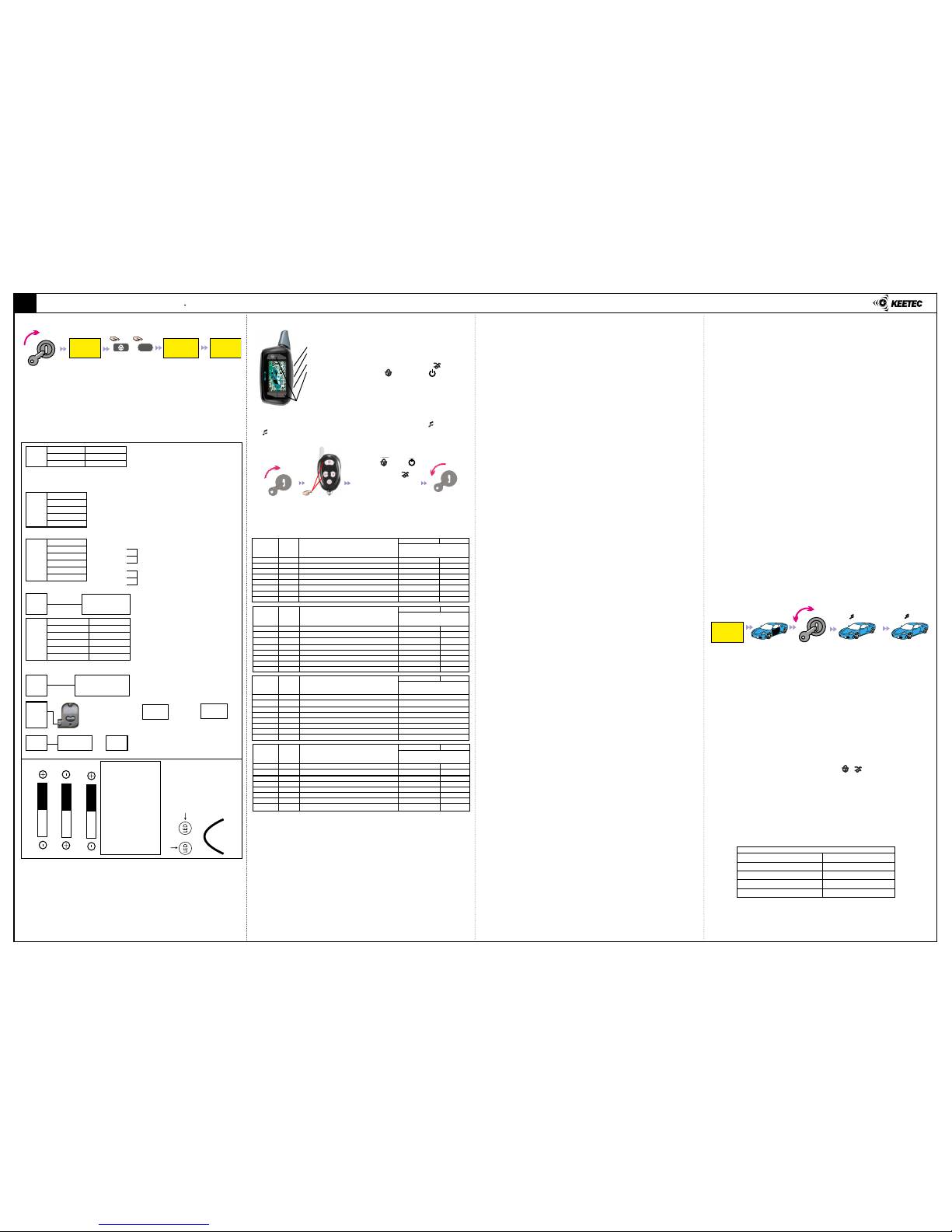
VI. TRANSMITTERS LEARNING
Set-up a valet mode. Open the vehicle door and turn ignition ON/OFF 8x or press
the service button 8x. The system will delete all learned transmitters automati-
cally. Learn the transmitter by button press of this transmitter. The system enables
to learn max.4 transmitters (max. 2 LCD transmitters). The car alarm allows to add
a new transmitter during alarm (if you loss or demage transmitter).
VII. VALET MODE EMERGENCY DEACTIVATION
Valet mode setting: Turn ignition ON and press button of RPS module for 5 sec.
LCD transmitter sounds 1x and display shows “VALET”. The system will work as cen-
tral lock in this mode. The process for deactivation of valet mode is the same as for
activation. LCD transmitter will sound 2x and “VALET” will disappear from display.
Emergency deactivation has the same process (at loss or damage of transmitter).
VIII. SYSTEM RESET
Control unit reset: In valet mode, press buttons a in the same time over 2
sec. till 30 sec. from turn ignition OFF. All settings in menu will change to default.
Transmitter reset: After control unit reset is necessary to reset the transmitter
too. Take out battery of transmitter, press and hold button M and in the same time
return the battery to the transmitter.
LCD transmitter with 2way communication
Transmitter with 1way communication
One-way transmitter can be change only in P-1 a P-2 of the program menu.
Program menu step is marked by chirp sound (ex: Menu 1-1 = 1x , 1-2 =
2x , ..)
PROGRAM TABLE
PROGRAM MENU P1 REMOTE START
1-1 Auto turbo protection
If this function is ON, the function maintains engine ON after the door is locked.
The turbo time is possible to change at program menu 3-7.
1-2 Door re-Lock after remore start (installation only)
If this function is ON, The car alarm will lock doors automatically after remote start
ending. This function is necessary to activate at vehicles, where the central lock
wil unlock after turn ignition OFF.
1-3 Trunk output change (installation only)
If this function is ON, (+) will always output at the remote start (orange wire nr.3,
connector CN2).
1-4 LPG reservation mode (optional)
If this function is ON, the engine will turn OFF automatically within 30 sec., if LPG
in gas line is empty when the engine turn OFF.
III. RPM SETTING FOR REMOTE START
The engine must have idle RPM at setting (600-700RPM). RPM setting is necessary
if the information about engine ON for remote start will obtain from Tach signal
(yellow wire, connector CN5).
IV. WIRE DIAGRAM
KEETEC TS 8000 CAR ALARM INSTALLATION MANUAL 2/2
SK
TECHNICAL PARAMETERS
Power supply 12V +/- 25%
Working temperature -30°C to 70°C
Stand-by mode 10mA
Transfer frequency 433,92 MHz
Alarm duration 30 sec
Engine ON
(Maintain idling
condition)
Press buttons in
the same time
for 2 sec.
OFF
ACC ON
OFF
ACC ON
1
2
4
3
Ignition
key ON
Press buttons 1 a 3 in
the same time to 30
sec. after ignition ON
The setting is completed
if the ignition key OFF
or turn o automatically
after 5 sec.
step 1 step 2 step 3 step 4
ON OFF
or
choose next function
move to P2
ON/OFF
Step 1: Press button 3x
Step 2: Select program menu P-1, P-2, P-3, P-4 by button
Step 3: Choose desired function by pressing of button
Step 4: Set-up function by button (ON) or button (OFF)
Step 5: Save the setting to control unit and nish program-
ming by button press
F
M
(This function is operated when you install LPG gas valve ON/OFF relay).
1-5 Auto reservation mode
If this function is ON, the reservation mode for remote start run always after turn
ignition OFF (The engine stays ON till last door closing - max. 2 min.).
If this function is OFF, the reservation mode is possible a manual activation (see
user manual - reservation mode for vehicle with manual gear).
1-6 Glow plug sensing at remote start (installation only)
If this function is ON, starter motor is operated after glow plug is OFF at the re-
mote start. For this function is necessary to connect violet wire nr. 11 (connector
CN5).
1-7 Cold & Hot start
If this function is ON, engine automatically start if temperature become under
-20° C or more then +50°C at the arm mode. The cold start temperature is possible
set-up from -4 to -24°C (program menu 3-4). The engine ON duration is depend
of function setting 3-1. This function is automatically OFF after total 8x operation.
1-8 Output “Ignition 2” at the disarm (installation only)
If this function is OFF, output “Ignition 2” is OFF at the disarm during remote start.
PROGRAM MENU P2 BASIC FUNCTIONS
2-1 Digital code valet mode
If this function is OFF, the valet mode is operated to ON/OFF if you press the valet
button for 5 seconds at the ignition key ON.
If this function is ON, set the security code at valet mode activation.
Digital code valet mode activation:
1. Press the switch for 5 seconds when the digital control module is standby mode,
and then LED blinks one time and the display segment is rotated fast. (This func-
tion is maintained for 30 seconds.).
2.
Knock the sensor more than 5 times after get o the car within 30 seconds,
then the digital code start count. (If you press the switch again within 30 seconds
LED blinks 2 times and digital valet function is canceled).
3. During the numbers automatically count with delay each 2 seconds from 0 to
9, knock the sensor at the registered CODE. Then selected number blinks 5 times
and it automatically repeat next number from “0”.
4. Select the remainder 3 CODES as upper STEP 3. If you select all CODES in order,
valet mode is ON. If you want to cancel the valet mode, press the valet button for
5 seconds at the ignition key ON.
2-2 Ignition lock/unlock
When turned ON, the doors will be locked when step on brake after the ignition is
turned ON. The doors will be unlocked when the ignition is turned OFF. Getting on
the vehicle during remote start: Door is locked when ignition key ON and then step
on the brake.
2-3 Passive arming
When turned ON, the system will arm automatically after 30seconds if the ignition
key is OFF and door open/close.
2-4 Passive lock
When turned ON: When the system is arm by passive arming, door lock will be
automatically operated.
2-5 Last door arming
When turned ON, if all door is closed at the disarm, door lock will be operated
with arm after 30 seconds.
2-6 Chirp sound
In the default setting, siren of the vehicle will output chirp sound when you ope-
rate transmitter.
2-7 Double unlocking pulse (installation only)
If this function is ON, each door unlock = 2 impulses. The function is activated,
when unlock impulse is setting on 0,5 sec. (program menu 4-3).
2-8 Double locking pulse (installation only)
If this function is ON, each door lock = 2 impulses. The function is activated, when
unlock impulse is setting on 0,5 sec. (program menu 4-3). If locking pulse is setting
in 20 sec., the rst impulse is 0,5 sec and the second is 20 sec.
PROGRAM MENU P3 TIMING SETTINGS
3-1 Run time for remote start
This function adjusts run time of the vehicle at remote start, cold start and time
reservation time.
3-2 Remote start delay
This function adjusts delay at remote start, delay time from turn ignition ON to
engine start.
3-3 Start impulse time (installation only)
Time setting of start impulse (at remote start by tach or noise sensing).
3-4 Cold start temperature settings
Minimal temperature setting for start of Cold & Hot program. The function Cold &
Hot start must be ON (1-7).
3-5 Aux 1 output (installation only)
Duration of Aux1 output setting. If CLH is adjusted, Aux1 output is constant (the
autput will be activated till disarm by transmitter).
3-6 Aux 2 output (installation only)
uration of Aux1 output setting. If CLH is adjusted, Aux1 output is constant (the
autput will be activated till disarm by transmitter).
Pro-
gram
menu
LCD
dis-
play
P-1 Remote start
Factory default Optional
Press button 1 or 2
1-1 tur Auto turbo protection OFF ON
1-2 StL Door re-lock after remote start OFF ON
1-3 ACC Trunk output change OFF ON
1-4 LPG LPG reservation mode OFF ON
1-5 Atr Auto reservation mode ON OFF
1-6 Het Glow plug sensing at remote start OFF ON
1-7 tEm Cold & Hot start OFF ON
1-8 lGt Output “ignition 2”at the disarm ON OFF
Pro-
gram.
menu
LCD
dis-
play
P-2 Basic function
Factory default Optional
Press button 1 or 2
2-1 CCH Digital code valet mode OFF ON
2-2 IGL Ignition lock/unlock OFF ON
2-3 PSA Passive arming OFF ON
2-4 PSL Passive lock OFF ON
2-5 LdA Last door arming OFF ON
2-6 CHP Chirp sound ON OFF
2-7 dUP Double unlocking pulse OFF ON
2-8 dLP Double locking impulse OFF ON
Pro-
gram.
menu
LCD
dis-
play
P-3 Timing settings
Factory default Optional
Press button 1 or 2
3-1 Stt Run time for remote start 2 10 15 25 35 45 (Minutes)
3-2 Std Remote start delay 4 8 12 15 18 20 (Sek.)
3-3 Sto Start impulse time
0.4 0.5 0.7 1.0 1.4 2.0 (Sec.)
3-4 CSt Cold start temperature settings -4 -8 -12 -16 -20 -24 (°C)
3-5 Au1 Aux 1 output (LCH=Continue) 1 5 10 20 40 LCH (Sec.)
3-6 Au2 Aux 2 output (LCH=Continue) 1 5 10 20 40 LCH (Sec.)
3-7 ttt Turbo time setting 1 2 3 5 8 10 (Minutes)
3-8 Amd Arm delay time setting 5 10 15 25 35 45 (Sec.)
Pro-
gram.
menu
LCD
dis-
play
P-4 Advanced functions
Factory default Optional
Press button 1 or 2
4-1 SPo Siren pulse output OFF ON
4-2 AEd Automatic engine disable OFF ON
4-3 Lot Unlock pulse 0,5 sec. 3,5 sec.
4-4 BPs Arm reminder OFF ON
4-5 dom Dome light is changed to armed output OFF ON
4-6 SAC SMART acces mode ON/OFF OFF ON
4-7 CAS Locking pulse As unlock 20 sec.
4-8 Acd Arm cancel mode at door open OFF ON
1: NC
2: COM
3: NO
4: NC
5: COM
6: NO
Lock Output
Unlock Output
CN 1
4 Green 1 White
5 Red 2 Black
6 Yellow 3 Blue
CN 2
1 White
2 White
3 Orange
4 Brown
5 Green
CN 3
1 Grey
2 Green
3 Yellow
4 Black
5 Blue
6 Orange
CN 4
CN 5
7 Red 1 White
8 Yellow 2 Black
9 Blue 3 Brown
10 Pink 4 Green
11 Violet 5 Grey
12 Orange 6 Blue
CN 6
CN 8 CN 9
CN 10 CN 11
1: (+) Starter - output (30A)
2: (
-
) Ground - output
3: (+) Ignition 2 - output (30A)
4: (+) Ignition 3 - output (30A)
5: (+) Power supply +12V - input
6: (+) Ignition 1 - output (30A)
1: (+) Direction indicators - output (10A)
2: (+) Direction indicators - output (10A)
3: (+/
-
) Trunk open / additional ignition output (10A)
4: (+) Siren - output (2A)
5: (
-
) Bypass - output (250mA) (LPG relay)
1: (
-
) Engine-cut output 1 (250mA)
2: (
-
) Dome light (250mA)
3: (
-
) AUX1 (250mA)
4: (
-
) Trunk sensing
5: (
-
) Hood sensing
(
-
) Brake sensing
6: (
-
/+) Door sensing - input
7: (+) Alternator sensing - input
8: (
-
) Tach pulse - input
9: (
-
) AUX2 - output (250mA)
10: (
-
) Sequential output (250mA)
11: (+/
-
) Glow plug sensing - input
12: (+) Brake sensing
Trunk Output
(orange wire nr.3 conector CN2)
Door sensing
(blue wire nr.6 conector CN5)
Glow plug sensing
(violet wire nr.11 conector CN 5)
Jumper 3
Jumper 2
Jumper 1
DIP 3 - ON: Tach pulse sensing
(yellow wire nr.8, CN5)
DIP 2 - ON: Engine noise sensing - low
OFF: Engine noise sensing - high
DIP 1 - ON: Engine noise sensing
OFF: Alternator sensing
(red wire nr.7, CN5)
Indication for Tach pulse input
Yellow Red
Indication for noise
or alternator input
W1
Brown wire
Normal = manual gear
Cut = automatic gear
module M
CAN
2-stage shock
sensor
CN 7
Locking
Unlocking
Driver call sensor
Valet mode
Antenna
Additional
sensor
LED
Additional valet
button (optional)
M
+
Valet mode
ON
Idle rpm
are save in
memory
Valet mode
OFF
ON
OFF
ACC
Set-up
valet mode
ON
OFF
ACC 5x 2x
V. SYSTEM FUNCTIONS PROGRAMMING
The programming for 2-way and 1-way transmitter is dierent During program-
ming, the car alarm must be OFF.
Procced for functions setting in program table in next steps for 2-way and 1-way
transmitter dierently:
*
F
Table of contents
Other KEETEC Car Alarm manuals