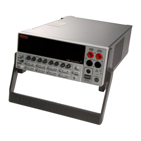
MODEL 660A DIFFERENTIAL VOLTMETER CONTENTS
TABLE OF CONTENTS
Section Page
1. GENERALDESCRIPTION ........ 1
1-1. Description ......... 1
1-2. Operating Modes ....... 1
l-3. Applications ........ 1
l-4. Specifications ....... 2
1-5. Accessories ......... 3
1-6. Equipment Shipped ... ... 3
2. OPERATION. ............ 5
2-l.
2-2.
2-3.
2-4.
2-5.
2-6.
2-7.
2-8.
2-9.
Front Panel Controls
and Terminals . . . . . . . 5
Rear Controls and
Terminals . . . . . . . . . 5
Preliminary Procedures . . 6
Operating Procedures . . . . 6
Recorder Output . . . . . . . 8
Effects Due to Kelvin-
Varley Divider Out-
put Resistance . . . . . . . 9
Loading and Off-Null
Resistance . . . . . . . . . 9
Thermal EMF Precau-
tions . . . . . , . . . . .lO
AC Effects on Measurement . .lO
3. APPLICATIONS . . . . . . . . . .lL
3-1. Procedures for Measuring
Resistances . , . . . . .
.lL
3-2. Theory of Measuring Resis-
tances . . . . . I . . . . .ll
4. CIRCUIT DESCRIPTION . . . . . . . .13
4-l. General . . . . , . . . . .13
4-2. Reference Voltage Supply . .13
4-3. Kelvin-Varley Divider . . . .14
4-4. Null Detector . . . . . . . .14
4-5. Guarding . . . . . , . .15
5. SERVICING . . . . . . . . . . . .17
5-l. General . , . . . . . .17
5-2. Servicing Schedule . . , . .17
5-3. Parts Replacement . . . , . .17
5-4. Troubleshooting . . . , . .L7
Section Page
6. CALIBRATION . . . . . . . . . 21
6-l. General . . . . . . . . . . 21
6-2. Calibration Schedule . . . 22
6-3. Kelvin-Varley Divider
Verification . . . . . . . 22
6-4. Range Calibration , . . . . 23
6-5. Reference Voltage Supply
Stability Test . . . . . . 25
6-6. Oscillator Adjustment . . . 27
7.
8.
ACCESSORIES , . . . . . , . . . . 35
7-L. Model 660LA High Voltage
Divider . , . . . . , , . 35
7-2. Rack Mounting . . . . . . . 35
7-3. Placing in Rack . . . . . 36
REPLACEABLE PARTS , . . . . . . : 37
5-5. Adjusting Hum Bal Control . 19
5-6. Zener Diode Replacement . . 19
5-7. Meter Adjustment . . . . . 19
8-l. Replaceable Parts List . . 37
8-2. How to Order Parts . . . . 37
Model 660A Replaceable
Parts List . . . . . . . . 38
Model 6601A Replaceable
Parts List . . . . . . . . 44
Model 66OA Schematic Diagram
182693. . . . . . . . . . 47
Model 6601A Schematic Diagram
1632LB . . . . . . . . . 49
$0Change Notice
-'- Yellow Change Notice sheet is in-
cluded only for instrument modifi-
cations affecting the Instruction
Manual.
1065R
