Vigilantplant SC72 User manual

User’s
Manual
IM 12D03D02-01E
Model SC72
Personal Conductivity Meter
IM 12D03D02-01E
1st Edition

1
Preface
IM 12D03D02-01E
1st Edition: Aug. 2004 (YK)
All Rights Reserved, Copyright © 2004, Yokogawa Electric Corporation
Preface
Before using the Model SC72 Personal Conductivity Meter, read this manual thoroughly.
For safe use of this meter, the meter and the instruction manual include the following
symbol marks.
WARNING
: Indicates that serious injury may result, if users fail to follow
instruction manual procedures.
CAUTION : Indicates that minor injury to personnel, or serious damage to
the product, may result if users fail to follow procedures in the
instruction manual.
WARNING
Do NOT use this instrument where there is a danger of electrical shock.
Do NOT touch any part of the electrode immediately after measuring very hot liquids —
otherwise, you may get burnt.
CAUTION
If the meter will not be used for an extended period of time, be sure to remove the
battery. Otherwise battery leakage may occur, and may cause damage to the meter or
cause erroneous meter operation.
The contents of this manual are subject to change without prior notice.
Yokogawa Electric Corporation assumes no liability for damage, defects, or loss of the
product caused by any of the following:
User error;
Inappropriate or out-of-specifications use of the product;
Use in an unsuitable environment;
Repair or modification of this or related products by persons other than Yokogawa-
authorized engineers.

IM 12D03D02-01E
2
Preface
Liquid crystal display (LCD) display characters
The numeric LCD display is used to mimic alphabetic characters, as shown below:
9
8
7
6
5
4
3
2
1
0
Z
Y
X
W
V
U
T
S
R
Q
P
O
N
M
L
K
J
I
H
G
F
E
D
C
B
A
Alphabet DisplayAlphabet Display DisplayNumerals
F00.EPS
All display elements shown ON
Note Regarding Panels Shown in this Manual:
Panels shown in this manual should be regarded as examples. Actual panel format may
vary depending on parameter settings and on type of connected sensor.
Showing all display elements lit
Display (gray represents flashing state)
Flashing state: Lit state:

IM 12D03D02-01E 3
Preface
Warranty and Service
Yokogawa products and parts are guaranteed to be free from defects in workmanship and
materials under normal use and service for a period of (typically) 12 months from the
date of shipment from the manufacturer.
Individual sales units may offer different warranty periods, so the original purchase order
should be consulted for the conditions of sale. Damage caused by normal wear and tear,
inadequate maintenance, corrosion, or due to chemical processes, is excluded from this
warranty coverage.
In the event of a warranty claim, any items that are considered to be defective should be
sent (freight paid) for repair or replacement (at Yokogawa discretion) to the service
department of the relevant sales unit. The following information must be included in a
letter accompanying the returned items:
Model code and serial number
Copy of original purchase order showing the date
Length of time used, and the measuring environment
Fault symptoms, and circumstances of failure
Statement whether service under warranty or out-of-warranty service is requested
Complete shipping and billing instructions for return of goods, plus the name and
phone number of a contact person who can be reached for further information
Goods that have been in contact with process fluids must be decontaminated / disinfected
before shipment, and a statement to this effect should be included. Safety data sheets for
all process components that the goods have exposed to should also be included.

IM 12D03D02-01E
4
Contents
CONTENTS
Preface...................................................................................................................... 1-1
1. Outline ................................................................................................................. 1-1
1.1 Features ......................................................................................................................... 1-1
1.2 Personal Conductivity Meter Specifications .................................................................. 1-2
1.3 When You Receive This Conductivity Meter................................................................. 1-3
1.4 Contents of Model SC72 Personal Conductivity Meter Package ................................. 1-4
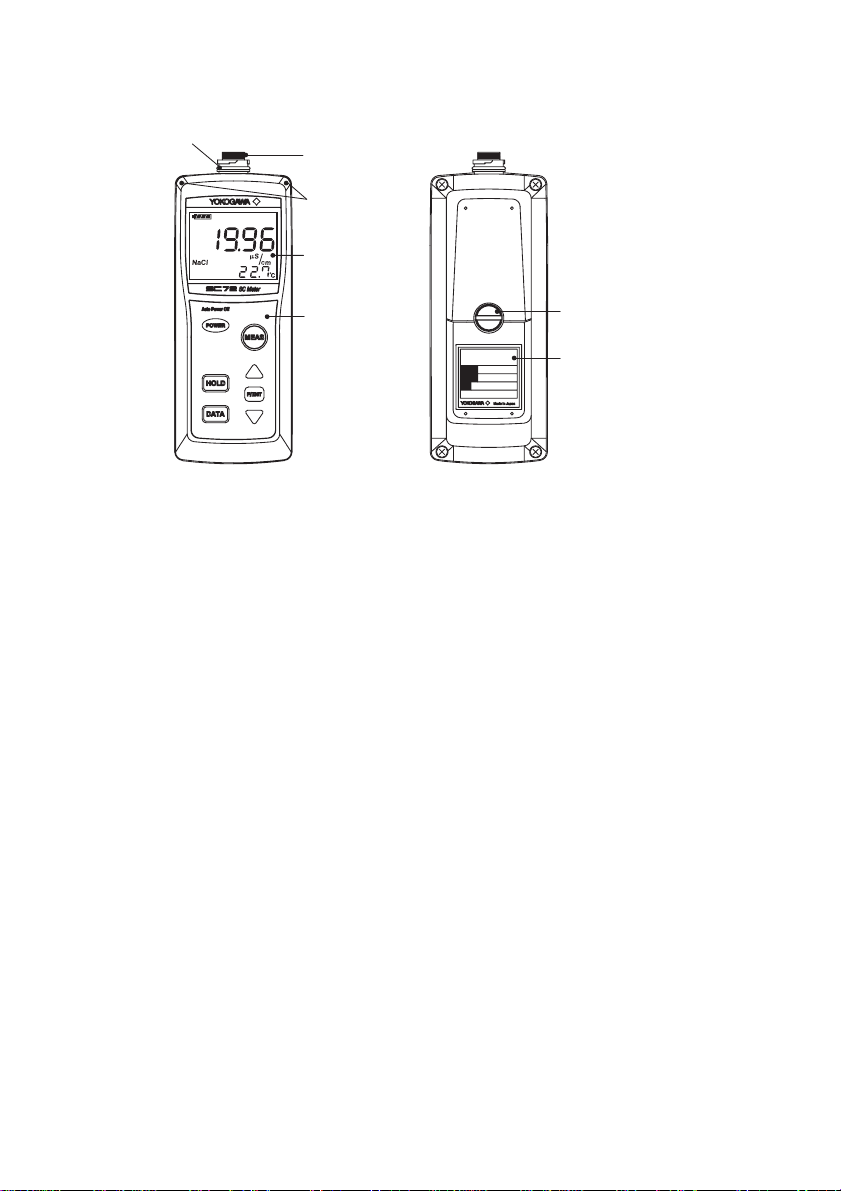
1.5 Component Names and Functions ................................................................................ 1-5
1.6 Sensor Part Names and Functions ............................................................................... 1-6
1.7 Options (Available Separately) ...................................................................................... 1-8
1.8 Spare Parts .................................................................................................................... 1-8
2. Preparation.......................................................................................................... 2-1
2.1 Installing the Batteries ................................................................................................... 2-1
2.2 Connecting Sensor Cable.............................................................................................. 2-2
2.3 Setting Date and Time................................................................................................... 2-3
2.4 Setting Temperature Unit .............................................................................................. 2-4
2.5 Setting Cell Constant ..................................................................................................... 2-4
2.6 Setting Temperature Compensation Coefficient ........................................................... 2-6
3. Measurement ...................................................................................................... 3-1
3.1 Precautions .................................................................................................................... 3-1
3.2 Measurement Procedures ............................................................................................. 3-2
3.3 Measurement Panel....................................................................................................... 3-3
3.4 Saving Measured Value ................................................................................................ 3-3
4. Keyswitch Functions.......................................................................................... 4-1
4.1 Names and Functions of Keys ...................................................................................... 4-2
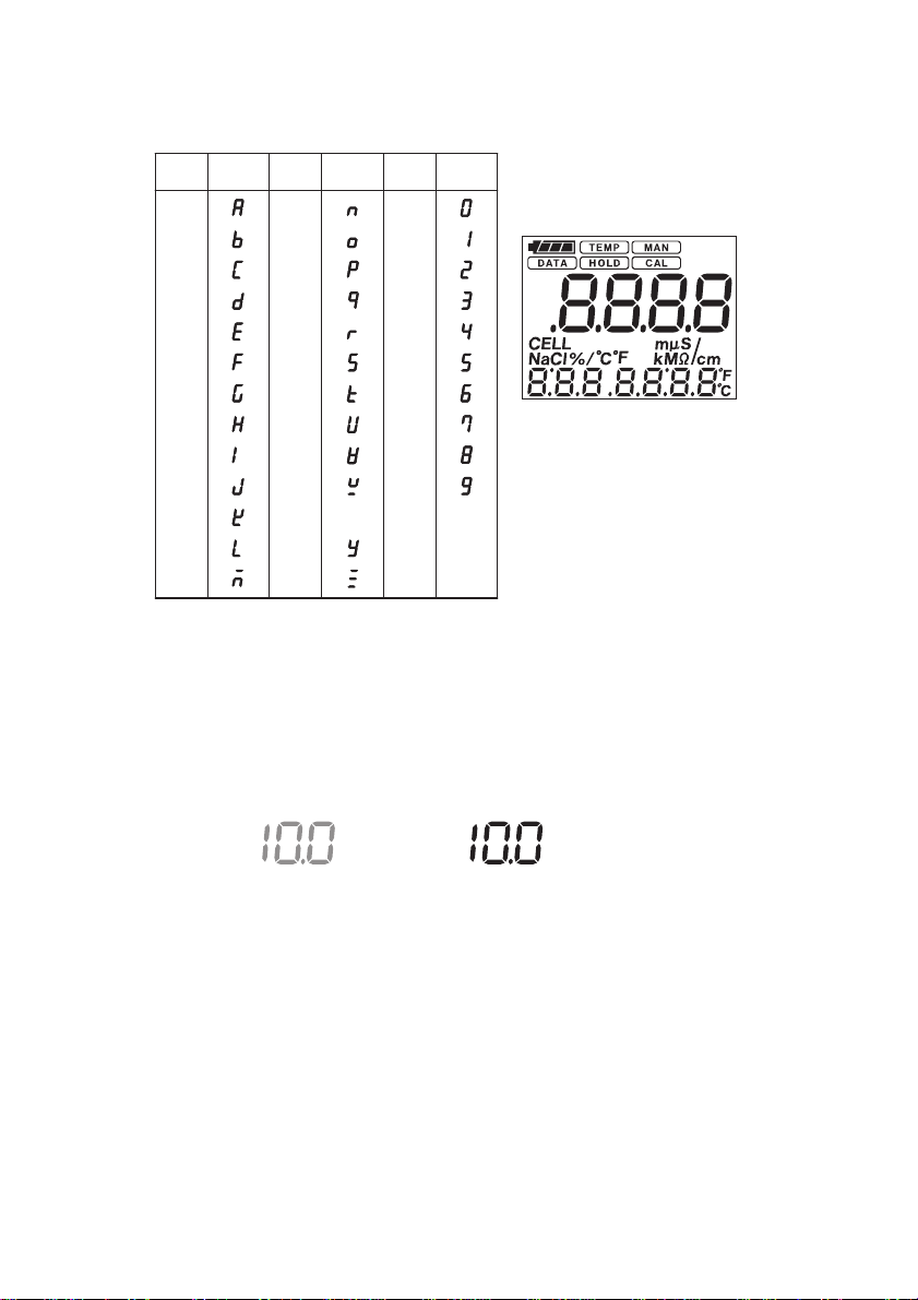
4.2 Liquid Crystal Display and Display Items ...................................................................... 4-4
4.3 Function Modes ............................................................................................................. 4-5
5. Handling of the SC72 Personal Conductivity Meter ........................................ 5-1
5.1 Tips to Maintain Meter Performance ............................................................................. 5-1
5.2 Washing the Electrode .................................................................................................. 5-2
5.3 Cleaning and Drying Connector .................................................................................... 5-3
5.4 Calibration with Standard Solution ................................................................................ 5-4
5.5 Storage and Maintenance ............................................................................................. 5-7
6. Troubleshooting ................................................................................................. 6-1
6.1 Causes of Abnormal Conductivity Display .................................................................... 6-1
6.2 Error Messages and Corrective Action ......................................................................... 6-2
6.3 Causes of Abnormal Measured Value .......................................................................... 6-4
6.4 Other conditions............................................................................................................. 6-4
7. Measuring Principles of this Instrument .......................................................... 7-1
7.1 What Is Conductivity? .................................................................................................... 7-1
7.2 Principles of Operation .................................................................................................. 7-2
7.3 Temperature Compensation and Finding Temperature Compensation Coefficient ..... 7-3
7.4 Wetted Part Materials of Sensors ................................................................................. 7-4
Appendix ..................................................................................................................... 1
Revision Record .......................................................................................................... i

IM 12D03D02-01E 1-1
1.Outline
1. Outline
The Model SC72 Personal Conductivity Meter is an accurate, portable, easy-to-use
conductivity meter. It includes not only self-diagnostic functions, to help ensure validity
of readings, but also data storage functions to allow users to check past data. The meter
is of waterproof construction so that it can safely be used outdoors on a rainy day, and
can also withstand being accidentally dropped into water.
1.1 Features
Water resistant case
When this meter is used with its dedicated sensor, it meets the requirements of class IP67
“Degree of Protection to be Provided by Enclosures” in IEC 60529.
Wide measurement range, and convenient “Auto Range” function
Sensors are available to cover measurement ranges between 0 to 2.000 mS/cm and 0 to 2
S/cm. Auto-range functions automatically set the optimum measurement range, making
measurement easy.
Automatic temperature compensation
Automatic temperature compensation functions are provided for liquid measurement.
Conductivity referenced to 258C can be obtained in solutions with temperature
coefficients between 0.00 and 9.99%/8C. The temperature coefficients for NaCl solutions
are already stored in the meter.
Calendar and time functions
Internal time functions allow “one-touch checking” of measurement date and time.
Data storage function
Up to 300 conductivities and temperature measurements, and their measurement date and
time, can be saved. This function allows you to check past measurement data.
Automatic power off function
The meter will power off automatically if not operated during a preset time interval.
The time interval can be set in one-minute increments in the range 1 to 120 minutes to
meet your application requirements. This automatic power off function can also be
disabled, but it is wise to leave it enabled to conserve the batteries.
Simple alarm clock function
The meter can issue an alarm signal at a specified time. Even when meter power is
turned off, the internal clock can issue an alarm signal.
Internal self-diagnostic functions display messages when appropriate.
Bright easy-to view large LCD
Displays liquid conductivity, liquid temperature, temperature coefficient, date and time.

IM 12D03D02-01E
1-2
1.Outline
1.2 Personal Conductivity Meter Specifications
Applicable measurement range:
• Sensors for high purity water measurement (cell constant: 0.05 cm-1)
Conductivity: 0 to 2mS/cm, 0 to 20mS/cm, 0 to 200mS/cm, 0 to 40MV•cm
Temperature: 0 to 808C
• For general-purpose sensors (cell constant: 5 cm-1)
Conductivity: 0 to 20mS/cm, 0 to 200mS/cm, 0 to 2mS/cm, 0 to 20mS/cm,
0 to 200mS/cm,
Temperature: 0 to 808C
• For chemical-corrosion-resistant sensors (cell constant: 5 cm-1)
Conductivity: 0 to 20mS/cm, 0 to 200mS/cm, 0 to 2mS/cm, 0 to 20mS/cm,
0 to 200mS/cm
Temperature: 0 to 808C
• Sensors for high-conductivity measurement (cell constant: 50 cm-1)
Conductivity: 0 to 2mS/cm, 0 to 20mS/cm, 0 to 200mS/cm, 0 to 2S/cm
Temperature: 0 to 808C
Resolution: Conductivity: Least significant digit: 1 digit;
Temperature: 0.18C
Repeatability (Conductivity):
62% (65% for general-purpose sensor on 0 to 200mS/cm measurement range)
Accuracy (Temperature): 60.78C (in the range 0 to 708C)
618C (when exceeding 708C)
Temperature compensation range:
variable 0.00 to 9.99%/8C, also (preset) NaCl solution temperature coefficient
Measurement converted to conductivity at standard temperature of 258C
Measured liquid temperature: 0 to 808C (0 to 508C when the sensor cable is immersed in
water)
Ambient temperature:0 to 508C
Construction: IEC 60529, IP67 class of protection from environment
Power requirement: Two of size AA batteries (LR6)
Automatic power off interval: May be set in range 1 to 120 minutes
Battery life: About 200 hours of continuous use, for long-life alkaline battery (life
may vary depending on battery type and ambient conditions)
External dimensions: Approximately 150 (H) x 61 (W) x 42 (D) mm (not including
protruding portions)
Weight: Approximately 220 g (including batteries)

IM 12D03D02-01E 1-3
1.Outline
1.3 When You Receive This Conductivity Meter
Confirm that all SC72 meter package components (refer to Contents of Model SC72
Personal Conductivity Meter Package in Section 1.4 and sensor models described in Sec.
1.6, “Sensor Part Names and Functions.”) have been received. Carefully inspect the
meter and sensor, referring to Section 1.5, “Component Names and Functions” when
assembling meter and sensor.
Particular attention should be taken:
* Not to twist or force the cable.
* Not to hit or drop the meter.
* Not to get the sensor connector dirty.

IM 12D03D02-01E
1-4
1.Outline
1.4 Contents of Model SC72 Personal Conductivity Meter
Package
11 11 11 11
Instrument Card
789
10
1
2
5
6
4
3
Quick Manual
User's
Manual
SC72---AA
SC72-11 --AA SC72-31--AA SC72-41--AA
*1*1*1*1
*1 The meter model number and cell constants, as well as the sensor model no. (SC72SN-u-AA), are
shown on the nameplate.
SC72-21--AA
SC72-23--AA
SC72
Sensors -00
-11
-21
-23
-31
-41
Label -J
language- E
--AA
Specification
1
2
3
4
5
6
7
8
9
10
11
No.Personalconductivitymeter
Two drybatteries
Two instruction manual
Non-slippads (two)
Hand strap
Instrument card
Sensor for high puritywater
measurement
General-purpose sensor
Chemical-resistant sensor
Sensor for high-conductivity
measurement
Sensor cleaner
(five cotton swabs)
Name
Model Suffix codePersonal conductivitymeter
Meter only, without sensor
With sensor for high puritywater measurement
(cable length:0.75m)
With general-purpose sensor
(cable length:0.75m)
With general-purpose sensor (cable length:3m)
With chemical-resistant sensor
(cable length:0.75m)
With sensor for high-conductiivitymeasurement
(cable length:0.75m)
Japanese
English
Always -AA
F010401.EPS

IM 12D03D02-01E 1-5
1.Outline
1.5 Component Names and Functions
PERSONAL
SC METER
2004.
SC72
S1.0
E000001
MODEL
No.
STYLE
Sensorcable connector
Display
Keyswitches
O-ring
Usedtoconnect adedicated
conductivitysensortothe
personal conductivitymeter.
Displaysconductivity,
temperature,and
temperature coefficient
simultaneously.
Can attachhandstraphere
Instrument nameplate
withmodel number
andserial number
Batteryboxcover fixingscrew
F010501.EPS

IM 12D03D02-01E
1-6
1.Outline
1.6 Sensor Part Names and Functions
Four types of sensors are available for use with the Model SC72 Personal Conductivity
Meter:
(1) sensor for high purity water measurement (cell constant 0.05 cm-1),
(2) general-purpose sensor (cell constant 5 cm-1),
(3) chemical-resistant sensor (cell constant 50 cm-1), and
(4) sensor for high-conductivity measurement (cell constant 50 cm-1). Check the model
number and cell constant on the name plate to confirm which type of sensor you
have.
Conductivity sensor for personal conductivity meter
For SC72;for high purity water measurement (cable
length: 0.75m)
For SC82;for high purity water measurement (cable
length: 0.75m)
For SC72;for general purpose type (cable length: 0.75m)
For SC72;for general purpose type (cable length: 3m)
For SC82;for general purpose type (cable length: 0.75m)
For SC72;for chemical-resistant type (cable length:
0.75m)
For SC82;for chemical-resistant type (cable length:
0.75m)
For SC72;for high conductivity measurement (cable
length: 0.75m)
For SC82;for high conductivity measurement (cable
length: 0.75m)
Always -AA
SC72SN
-11
-19
-21
-23
-29
-31
-39
-41
-49
-AA
Specification
K9221XB
K9221XA
K9221XC
K9221XD
RemarksModel Suffixcode
Model number and cell constants display plate example
SC72SNConductivity sensors for personal conductivity meter
F010601.EPS
*
2
*
1
*
1
*
1
*
1
S1.0000001-11-AA STYLE
CELL
CONST
Made in Japan
MODEL
SUFFIXNO.
SC72SN
Cell constants
*1: Waterproofing is not guaranteed if you use SC82-type conductivity sensor in conjunction
with SC72 meter.
*2: Old part number for SC82 conductivity meter.

IM 12D03D02-01E 1-7
1.Outline
F010602.EPS
Sensor for high purity water measurement
Outer electrode
(SUS316 stainless seel)
Outer electrode
connection
(SUS316
stainless seel) Sensor body
Sensor grip Sensor grip
Sensor
cable
Watertight cover
Connector
Modelnumber and
cell constants display plate
Inner electrode
(SUS316
stainless seel)
General-purpose sensor
Cover (Plastic)
Sensor bodySensor cable
Watertight
cover
Connector
Modelnumber and
cell constants display plate
Edge electrode
(Titanium)
Inner electrode
(Titanium)
Prevents moisture
from entering
connector andcausing
leakage between pins.
Connects sensor cable to
conductivity meter
Plasticbody can
withstandtemperatures
up to 808C.
SC72-11 --AA *1
*1
*1
SC72-21 --AA
SC72-23--AA
(SC72SN-11-AA)*1(SC72SN-21-AA,
SC72SN-23-AA)
F010603.EPS
Chemical-resistant sensor
Inner electrode
(platinum black)
Air vent Sensor body(glass)
Inner electrode
(platinum black)
Air vent Sensor body(glass)
Sensor
cable
Watertight
cover
Connector
Model number and
cell constants displayplate
Sensor for high-conductivitymeasurement
Sensor cable
Watertight
cover
Connector
Model number and
cell constants displayplate
*1SC72SN-uwill be describedon sensor's name plate for the model number.
SC72 - 31 - - AA SC72 - 41- - AA
*1*1
Sensor gripSensor grip
*1(SC72SN-31-AA)*1(SC72SN-41-AA)

IM 12D03D02-01E
1-8
1.Outline
1.7 Options (Available Separately)
The following options are available for the Personal Conductivity Meter for your
convenience. When ordering, specify part number shown below.
Sensor stand
(Part no.: K9220XN)
Soft case
(Part no.: B9269KJ)
Standard solution
(Part no.: K9221ZA)
This stand holds the sensor when
the conductivity meter is used on a
table. It is made of rustproof
stailess steel.
0.1mol/l NaCl solution for
calibration (250ml)This soft blackcarryingcase holds
conductivity meter and sensor.
Unit:mm
Approx. 30
Approx. 140
Approx. 280
F010701.EPS
1.8 Spare Parts
O-rings and gaskets are important parts to ensure that the SC72 meter is water resistant.
Replace these parts as required. Refer to Section 5.5, “Storage and Maintenance” for
replacement.
O-ring and gasket set
(Part no.: K9654AY)
Two battery box gaskets
Two sensor connection O-rings
F010801.EPS

IM 12D03D02-01E 2-1
2.Preparation
2. Preparation
2.1 Installing the Batteries
Install the batteries first.
CAUTION
Select a relatively moisture-free location when installing batteries in the meter.
When installing batteries, observe correct polarity (battery orientation).
Failure to do so may damage to the meter.
Remove batteries from the meter if it is to be stored for an extended period of time.
Do not leave dead batteries in the meter. They may leak and cause meter failure or
erratic operation of the meter.
When replacing batteries, replace both batteries at the same time. If only one battery is
replaced, the new battery may discharge into the old battery, which may leak chemicals
and damage the meter.
If the battery box gasket is damaged or dirty then the unit may no longer be waterproof;
replace the gasket in this case.
F020101.EPS
Gasket
(1) Loosen thebattery box
cover with acoin or thelike.
(2) Removebattery cover and
install batteries as shown in
figure.
(3) Checkfor foreign material
on sealing gasket around
battery box.
(4) Securetip of battery box
cover in thebattery box and
close thecover.
(5) Tighten thebattery box
cover with acoin or thelike.

IM 12D03D02-01E
2-2
2.Preparation
2.2 Connecting Sensor Cable
Connect the sensor cable as shown below.
CAUTION
Select a relatively moisture-free location when connecting the sensor cable.
Take care not to wet or dirty the connector when connecting the sensor cable.
Model SC82 sensors can be connected, but these are not guaranteed to be waterproof
when used with this meter.
F020201.eps
O-ring
(1)Pull the waterproof cover along the
sensor cable away from the
connector to expose the locknut.
(2)Connect the connector to the meter
body*, and tighten the locknut
firmly so that it won't come loose.
* Align sensor connector with sensor
body connector.
(3)Move the waterproof cover towards
the connector until it firmly
contacts the O-ring on the meter
body.
* Align sensor connector with sensor
body connector.
(4)Next turn the cover 90 degrees in the
direction shown in the figure to lock
it.
Locknut
Waterproof cover
(1)
(2)
(4)
(3)
Caution:It is recommended that, as far as possible, you leave the sensor connected to the
meter to help ensure that the connector does not get dirty.

IM 12D03D02-01E 2-3
2.Preparation
2.3 Setting Date and Time
After installing the batteries, set the date and time. Note that if the power is turned off
after setting “minutes,” start with the date setting when you turn on the power next time.
If you replace the batteries, the date is not affected, but the time is reset. Reenter the
time.
Caution:If the sensor is not connected then an error will be displayed on the meter.
• Setting method
After installing batteries, press and hold the
POWER
key for at least one second. Then
all display elements turn on and the date setting display automatically appears. Set year,
month, day, hours, and minutes as follows:
Caution:If you stop part way through the date and time setting then the meter will beep
and the date and time will not be updated.
F020301.EPS
key for at least 1sec.
After
pressing
to set
to confirm
to set
to set
to confirm
to confirm
to set
to confirm
Year setting
Daysetting Hour setting (24-hour format)
Monthsetting
Minute setting
After
several
seconds
After
several
seconds
POWER
F/ENT
F/ENT F/ENT
F/ENT
to set to confirm
or
F/ENT

IM 12D03D02-01E
2-4
2.Preparation
2.4 Setting Temperature Unit
Default temperature units are 8C. To change to 8F, refer to Sec. 4.3 (13) Set temperature
units (tP.U) panel.
2.5 Setting Cell Constant
Even for sensors of the same type, each sensor has its own distinct cell constant. So, set
the proper cell constant as indicated on the sensor cable.
Whenever sensors are replaced, be sure to change the cell constant setting in the meter
accordingly. Cell constants once set are stored in non-volatile memory and are not lost
even when the batteries are replaced.
• Setting cell constants
Press the
F/ENT
key to switch to function mode. Then select the C.C display with the
key and access the cell constant setting display with the
F/ENT
key. Use the
key to set the cell constant, then press the
F/ENT
key to confirm it.
Refer to Sec. 4.3 (4).

IM 12D03D02-01E 2-5
2.Preparation
F020501.EPS
F/ENT
F/ENT
F/ENT
MEAS
for Function mode
for C.Cpanel
to enter C.C
select C.C
You can abort this procedure at any time by pressing
MEAS
to revert to measurement
mode.

IM 12D03D02-01E
2-6
2.Preparation
2.6 Setting Temperature Compensation Coefficient
As described in Section 7.3, liquid conductivity varies with liquid temperature.
Therefore, if concentration is measured by conductivity, the conductivity must be
converted to equivalent conductivity at a certain temperature. This instrument
incorporates standard temperature conversion functions to convert liquid conductivity
measurements to equivalent conductivity at 258C. To display equivalent liquid
conductivity at 258C, set the temperature compensation coefficient as described in this
section.
Temperature coefficient for NaCl solutions is stored in this instrument. If any other
solution is used, set the temperature compensation coefficient manually.
Refer to Sec. 4.3 (2) Temperature compensation setting (t.Co) panel.

IM 12D03D02-01E 2-7
2.Preparation
• Set the temperature compensation coefficient
F020601.EPS
For NaCl solutions Manual setting
Set thetemperature
compensation coefficient
withthekeys.
MEAS MEAS
F/ENT
F/ENT
F/ENT
F/ENT
F/ENT
The temperature coefficient you set is displayed here
for Function mode
for t.Co panel
select t.Co
select NaCl or
%/8C (%/8F)
Table of contents
Other Vigilantplant Measuring Instrument manuals