KELVIN HUGHES CAE-A30/7 User manual

CHAPTER 1
INTRODUCTION
GENERAL
1 This technical manual covers the low speed transceiver and turning mechanism
CAE-A30/7 and the high speed transceiver and turning mechanism CAE-A30/8. For
information on earlier versions of the equipment refer to Publication KH 1203.
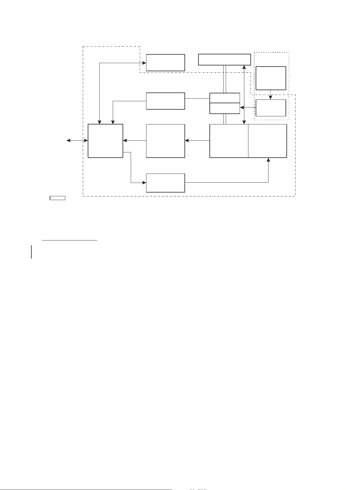
2 The transceiver may be interfaced with any of the Nucleus 2 and 3 Series displays via a
parallel interface or the NUCLEUS 3 series displays only via a Controller Access
Network (CAN) Bus link, the CANbus link being interfaced to the transceiver via a Transmitter
Interface Unit (TIU). When the parallel interface is used the Low Speed Turning Mechanism
(CAE-A30/7) uses +27V power supply from the display unit to drive the turning motor, whereas
the High Speed Turning Mechanism (CAE-A30/8) uses an external 40V Power Supply Unit
which is bulkhead mounted below deck. When the CANbus interface is used, the power supplies
are provided by the Transmitter Interface Unit for both low and high speed turning mechanisms
(the voltage can be set to meet the requirement of the specific turning mechanism).
3 Forward planning for positioning the various units of the Radar must be made before any
installation work is carried out. A full survey is required in order to establish the ship’s
fitment. This may be arranged with the Technical Department of Kelvin Hughes or one of the
approved Agencies. Details of Agencies worldwide can be found in Publication KH 401. Kelvin
Hughes, or appointed agents, contract to supply and install the equipment. It is recommended
that the installation is made by a fully qualified Kelvin Hughes Radar Engineer.
Compass Safe Distances
4 Compass safe distances are stated on labels on all units and are as follows:
Grade I (0.25 degree) Grade II (1 degree)
MkV Transceiver 3.0m 1.8m
Transceiver Unit Siting
5 The Transceiver is to be mounted on a rigid platform, which is positioned so that the
rotating antenna is clear of other structures.
6 The Transceiver/Antenna assembly should be installed in a position that eliminates or
minimises blind arcs caused by obstructions, e.g. masts, etc.
7 The primary consideration must be the strength of the support for the
Transceiver/Antenna assembly. Details of this requirement are described in the
following sub-paragraphs :
(1) The antenna must be mounted more than 3ft (914mm) above any flat surface
greater than the diameter swept by the antenna. It must not be positioned in close
proximity of any magnetic compass or D/F aerial etc.
KH1207
Chapter 1
mkv 3 Amdt 3 (Mar 01)

(2) Masts, sampsons, posts and rigging of more than 0.6m (2ft) diameter can cause
blind sectors. Increasing the distance between the antenna unit and these objects
will reduce the blind sectors that inhibit a good radar picture. Funnels, crosstrees
and other large areas can reflect energy and give rise to spurious echo returns
especially in close proximity to land. Positioning the antenna close to funnels and
exhaust gasses can adversely affect antenna performance. The antenna units must
not be mounted where the temperature exceeds 70°C.
(3) Antennas must be kept clear of ships radio and communication aerials to avoid
electrical RF interference that will cause reflections on the radar PPI display.
NOTE: A heavy duty earthing strap or cable must be taken from the scanner unit to the ship’s
earth.
8 The Antenna is to be mounted onto the Transceiver/Gearbox using the ‘O’ ring and
fixings supplied. Dimensions and weights for the unit are given in Chapter 2.
Power Supply Unit Siting
9 The Power Supply Unit (CZZ-A22) is only required for the High Speed Turning
Mechanism (CAE-A30/8). It is bulkhead mounted in a protected environment and is
secured by four fixings.
SYSTEM DESCRIPTION
10 The MkV Transceiver (CAE-A30/7 and CAE-A30/8) comprises the following main
units:
(1) Terminals PCB.
(2) Modulator.
(3) Magnetron/RF Head.
(4) Azimuth PCB.
(5) Receiver.
(6) Tx Monitor (Optional).
(7) Brushless Motor PCB (CAE-A30/8 only).
11 The 40V Power Supply (CZZ-A22), used on the High Speed Turning Mechanism
(CAE-A30/8) only, is a separate item of equipment, which is mounted below decks. This
is only required when the parallel interface is used. When the CANbus interface is used the TIU
supplies either +26V (low speed turning mechanism) or +36V (high speed turning mechanism)
for the antenna turning motor, selected by a switch on the power supply.
KH1207
Chapter 1
Amdt 3 (Mar 01) 4 mkv

Terminals PCB
12 The Terminals PCB feeds the incoming power and data from the display to the other
assemblies, providing modulator trigger pulses, pulse selection gating, antenna
switching, voltage regulation and tune voltage. The PCB also receives the video from the
Receiver and feeds the signals to the display processor.
Modulator
13 The Modulator provides a high voltage pulsed supply via a pulse width circuit and FET
circuit into a pulse transformer to drive the Magnetron.
RF Head
14 The RF Head contains the Magnetron, Ferrite Circulator, Pulse Limiter and Low Noise
Front End (LNFE). The LNFE comprises an RF Amplifier, Local Oscillator and IF Head
Amplifier.
15 The magnetron energy is fed to the circulator and via the rotating joint to the antenna. The
small leakage of power across the circulator, is fed into the pulse limiter and used by the
LNFE as a tune signal.
16 Return signals from the antenna are fed through the circulator to the limiter and the
LNFE, where they are amplified, mixed and converted to IF levels to interface with the
Receiver main IF.
Receiver
17 The Receiver amplifies and filters the IF from the RF Head and then feeds the signal to an
eight stage logarithmic amplifier which produces the video for the display monitor.
Azimuth PCB
18 The Heading Line and Azimuth data are produced by the interaction between an
opto-interrupter disc and sensors located on the PCB.
Brushless Motor PCB (CAE-A30/8 only)
19 The Brushless Motor PCB provides switching of the 40V supply to drive the motor
within the transceiver/turning mechanism at a constant speed.
+26V Motor Start PCB
20 Provides switching of +26V supply to drive the low speed motor. LK1 is made for
CAE-A30-7.
KH1207
Chapter 1
mkv 5 Amdt 5 (Oct 01)

40V Power Supply
21 The 40V Power Supply (CAE-A30-8 only) is bulkhead mounted below decks and is
connected the Transceiver by a cable. The unit consists of a +40V power supply with
associated control, filter and indicator circuits. A switch mounted on the top panel of the unit
allows the power supply to be switched off. The 40V Power Supply is connected to the
Transceiver/Turning Mechanism via the Display, Interswitch Unit or In Line Power Supply.
KH1207
Chapter 1
Amdt 5 (Oct 01) 6 mkv
AERIAL
GEARBOX
AZIMUTH
PCB
CAE-A402/3
RF
HEAD MAGNETRON
Tx Monitor
(OPT)
CTX-A198
RECEIVER
CTX-C356
TERMINALS
PCB
CTX-A368
VIDEO VIDEO
TO/FROM
DISPLAY
OR
INTERSWITCH
UNIT OR
IN LINE PSU
POWER
RF POWER
MODULATOR
CTX-A332
CD-3711
BRUSHLESS
MOTOR PCB
CAE-A236
40V PSU
CZZ-A22
(LOCATED
DOWNMAST)
MOTOR
THESE ITEMS
FOR CAE-A30/8
ONLY
UNITS LOCATED WITHIN
TURNING MECHANISM
Figure 1 - System Block Diagram
This manual suits for next models
1
Table of contents
Other KELVIN HUGHES Transceiver manuals