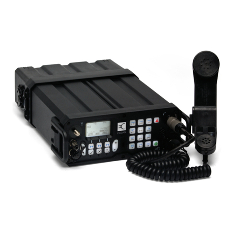
Codan 2110 series Assembly instructions

Manpack Transceiver 2110 series
Repair Guide
No part of this guide may be reproduced, transcribed, translated into any language or
transmitted in any form whatsoever without the prior written consent of Codan Limited.
© Copyright 2010 Codan Limited.
CODAN™, NGT™, Easitalk™, CIB™ and CALM™ are registered trademarks of
Codan Limited. Other brand, product and company names mentioned in this document
are trademarks or registered trademarks of their respective holders.
Codan part number 15-04139-EN Issue 1, October 2010.
The English version takes precedence over any translated versions.

www.codan.com.au
Head Office
Codan Limited
ABN 77 007 590 605
81 Graves Street
Newton SA 5074
AUSTRALIA
Telephone +61 8 8305 0311
Facsimile +61 8 8305 0411
asiatech.support@codan.com.au
Codan (UK) Ltd
Unit C4 Endeavour Place
Coxbridge Business Park
Farnham Surrey GU10 5EH
UNITED KINGDOM
Telephone +44 1252 717 272
Facsimile +44 1252 717 337
uktech.support@codan.com.au
Codan US, Inc.
1 Fishers Road
Pittsford NY 14534
USA
Telephone +1 585 419 9970
Facsimile +1 585 419 9971
hfsupport@codanusinc.com

Manpack Transceiver 2110 series Repair Guide i
Table of contents
Index
Introduction
Overview of this guide. . . . . . . . . . . . . . . . . . . . . . . . . . . . . . . . . . . . . . . . . . . . . . . . . . . . . . . . . . .1
How to use this guide. . . . . . . . . . . . . . . . . . . . . . . . . . . . . . . . . . . . . . . . . . . . . . . . . . . . . . . . . . . .2
Board replacement philosophy . . . . . . . . . . . . . . . . . . . . . . . . . . . . . . . . . . . . . . . . . . . . . . . . . . . .2
Disposal . . . . . . . . . . . . . . . . . . . . . . . . . . . . . . . . . . . . . . . . . . . . . . . . . . . . . . . . . . . . . . . . . . . . . .2
Circuit board precautions. . . . . . . . . . . . . . . . . . . . . . . . . . . . . . . . . . . . . . . . . . . . . . . . . . . . . . . . .3
Transmitter precautions . . . . . . . . . . . . . . . . . . . . . . . . . . . . . . . . . . . . . . . . . . . . . . . . . . . . . . . . . .4
Probe precautions. . . . . . . . . . . . . . . . . . . . . . . . . . . . . . . . . . . . . . . . . . . . . . . . . . . . . . . . . . . . . . .4
Contact information
Ordering information
Overview
General . . . . . . . . . . . . . . . . . . . . . . . . . . . . . . . . . . . . . . . . . . . . . . . . . . . . . . . . . . . . . . . . . . . . . . . .10
Connectors . . . . . . . . . . . . . . . . . . . . . . . . . . . . . . . . . . . . . . . . . . . . . . . . . . . . . . . . . . . . . . . . . . . . .11
Front panel . . . . . . . . . . . . . . . . . . . . . . . . . . . . . . . . . . . . . . . . . . . . . . . . . . . . . . . . . . . . . . . . . . .11
Back panel . . . . . . . . . . . . . . . . . . . . . . . . . . . . . . . . . . . . . . . . . . . . . . . . . . . . . . . . . . . . . . . . . . .16
Battery pack . . . . . . . . . . . . . . . . . . . . . . . . . . . . . . . . . . . . . . . . . . . . . . . . . . . . . . . . . . . . . . . . . .18
Brief description
General information . . . . . . . . . . . . . . . . . . . . . . . . . . . . . . . . . . . . . . . . . . . . . . . . . . . . . . . . . . . . . .21
Transmit path . . . . . . . . . . . . . . . . . . . . . . . . . . . . . . . . . . . . . . . . . . . . . . . . . . . . . . . . . . . . . . . . . . .22
Front Panel PCB . . . . . . . . . . . . . . . . . . . . . . . . . . . . . . . . . . . . . . . . . . . . . . . . . . . . . . . . . . . . . .22
Audio & Control PCB . . . . . . . . . . . . . . . . . . . . . . . . . . . . . . . . . . . . . . . . . . . . . . . . . . . . . . . . . .22
RF/IF & Synthesiser PCB . . . . . . . . . . . . . . . . . . . . . . . . . . . . . . . . . . . . . . . . . . . . . . . . . . . . . . .22
PA & Filter PCB . . . . . . . . . . . . . . . . . . . . . . . . . . . . . . . . . . . . . . . . . . . . . . . . . . . . . . . . . . . . . .22
Antenna Tuner PCB. . . . . . . . . . . . . . . . . . . . . . . . . . . . . . . . . . . . . . . . . . . . . . . . . . . . . . . . . . . .22
Receive path . . . . . . . . . . . . . . . . . . . . . . . . . . . . . . . . . . . . . . . . . . . . . . . . . . . . . . . . . . . . . . . . . . . .23
Antenna Tuner PCB. . . . . . . . . . . . . . . . . . . . . . . . . . . . . . . . . . . . . . . . . . . . . . . . . . . . . . . . . . . .23
PA & Filter PCB . . . . . . . . . . . . . . . . . . . . . . . . . . . . . . . . . . . . . . . . . . . . . . . . . . . . . . . . . . . . . .23
RF/IF & Synthesiser PCB . . . . . . . . . . . . . . . . . . . . . . . . . . . . . . . . . . . . . . . . . . . . . . . . . . . . . . .23
Audio & Control PCB . . . . . . . . . . . . . . . . . . . . . . . . . . . . . . . . . . . . . . . . . . . . . . . . . . . . . . . . . .23
Front Panel PCB . . . . . . . . . . . . . . . . . . . . . . . . . . . . . . . . . . . . . . . . . . . . . . . . . . . . . . . . . . . . . .23
Antenna tuning process . . . . . . . . . . . . . . . . . . . . . . . . . . . . . . . . . . . . . . . . . . . . . . . . . . . . . . . . . . .24
Synthesiser operation . . . . . . . . . . . . . . . . . . . . . . . . . . . . . . . . . . . . . . . . . . . . . . . . . . . . . . . . . . . . .24
Control and switching. . . . . . . . . . . . . . . . . . . . . . . . . . . . . . . . . . . . . . . . . . . . . . . . . . . . . . . . . . . . .24

Table of contents
ii Manpack Transceiver 2110 series Repair Guide
Interconnection diagrams and listed spares drawings
Functional description of PCBs
RF/IF & Synthesiser PCB . . . . . . . . . . . . . . . . . . . . . . . . . . . . . . . . . . . . . . . . . . . . . . . . . . . . . . . . . 33
PA & Filter PCB . . . . . . . . . . . . . . . . . . . . . . . . . . . . . . . . . . . . . . . . . . . . . . . . . . . . . . . . . . . . . . . . 37
Audio & Control PCB . . . . . . . . . . . . . . . . . . . . . . . . . . . . . . . . . . . . . . . . . . . . . . . . . . . . . . . . . . . . 40
Antenna Tuner PCB. . . . . . . . . . . . . . . . . . . . . . . . . . . . . . . . . . . . . . . . . . . . . . . . . . . . . . . . . . . . . . 44
Front Panel Assembly . . . . . . . . . . . . . . . . . . . . . . . . . . . . . . . . . . . . . . . . . . . . . . . . . . . . . . . . . . . . 46
Front Panel PCB . . . . . . . . . . . . . . . . . . . . . . . . . . . . . . . . . . . . . . . . . . . . . . . . . . . . . . . . . . . . . . . . 48
Repair procedures, tests, and adjustments
Test equipment . . . . . . . . . . . . . . . . . . . . . . . . . . . . . . . . . . . . . . . . . . . . . . . . . . . . . . . . . . . . . . . . . 52
Setup of test equipment for 2110. . . . . . . . . . . . . . . . . . . . . . . . . . . . . . . . . . . . . . . . . . . . . . . . . . . . 54
Repair procedures and fault diagnosis. . . . . . . . . . . . . . . . . . . . . . . . . . . . . . . . . . . . . . . . . . . . . . . . 55
General . . . . . . . . . . . . . . . . . . . . . . . . . . . . . . . . . . . . . . . . . . . . . . . . . . . . . . . . . . . . . . . . . . . . . 55
Mechanical inspection . . . . . . . . . . . . . . . . . . . . . . . . . . . . . . . . . . . . . . . . . . . . . . . . . . . . . . . . . 58
Operational tests . . . . . . . . . . . . . . . . . . . . . . . . . . . . . . . . . . . . . . . . . . . . . . . . . . . . . . . . . . . . . . 59
Receive tests . . . . . . . . . . . . . . . . . . . . . . . . . . . . . . . . . . . . . . . . . . . . . . . . . . . . . . . . . . . . . . . . . 63
Transmit tests . . . . . . . . . . . . . . . . . . . . . . . . . . . . . . . . . . . . . . . . . . . . . . . . . . . . . . . . . . . . . . . . 68
Disassembling the transceiver . . . . . . . . . . . . . . . . . . . . . . . . . . . . . . . . . . . . . . . . . . . . . . . . . . . . . . 77
Adjustments . . . . . . . . . . . . . . . . . . . . . . . . . . . . . . . . . . . . . . . . . . . . . . . . . . . . . . . . . . . . . . . . . . . . 79
Adjusting frequency . . . . . . . . . . . . . . . . . . . . . . . . . . . . . . . . . . . . . . . . . . . . . . . . . . . . . . . . . . . 79
Adjusting the PA. . . . . . . . . . . . . . . . . . . . . . . . . . . . . . . . . . . . . . . . . . . . . . . . . . . . . . . . . . . . . . 79
Re-assembling the transceiver . . . . . . . . . . . . . . . . . . . . . . . . . . . . . . . . . . . . . . . . . . . . . . . . . . . . . . 83
Checking the battery charging process . . . . . . . . . . . . . . . . . . . . . . . . . . . . . . . . . . . . . . . . . . . . . . . 86
Replacing battery cells. . . . . . . . . . . . . . . . . . . . . . . . . . . . . . . . . . . . . . . . . . . . . . . . . . . . . . . . . . . . 90
Replacing the fuse in the battery pack . . . . . . . . . . . . . . . . . . . . . . . . . . . . . . . . . . . . . . . . . . . . . 91
Flowcharts . . . . . . . . . . . . . . . . . . . . . . . . . . . . . . . . . . . . . . . . . . . . . . . . . . . . . . . . . . . . . . . . . . . . . 93
Test sheet for the 2110 series Manpack Transceiver. . . . . . . . . . . . . . . . . . . . . . . . . . . . . . . . . . . . 109
Options
Definitions
Standards and icons . . . . . . . . . . . . . . . . . . . . . . . . . . . . . . . . . . . . . . . . . . . . . . . . . . . . . . . . . . . . . 119
Definitions . . . . . . . . . . . . . . . . . . . . . . . . . . . . . . . . . . . . . . . . . . . . . . . . . . . . . . . . . . . . . . . . . . . . 120
Acronyms and abbreviations . . . . . . . . . . . . . . . . . . . . . . . . . . . . . . . . . . . . . . . . . . . . . . . . . . . 120
Glossary . . . . . . . . . . . . . . . . . . . . . . . . . . . . . . . . . . . . . . . . . . . . . . . . . . . . . . . . . . . . . . . . . . . 122
Circuit reference designations . . . . . . . . . . . . . . . . . . . . . . . . . . . . . . . . . . . . . . . . . . . . . . . . . . 123
Units . . . . . . . . . . . . . . . . . . . . . . . . . . . . . . . . . . . . . . . . . . . . . . . . . . . . . . . . . . . . . . . . . . . . . . 124
Unit multipliers . . . . . . . . . . . . . . . . . . . . . . . . . . . . . . . . . . . . . . . . . . . . . . . . . . . . . . . . . . . . . . 124
About this issue . . . . . . . . . . . . . . . . . . . . . . . . . . . . . . . . . . . . . . . . . . . . . . . . . . . . . . . . . . . . . . . . 125

Table of contents
Manpack Transceiver 2110 series Repair Guide iii
Specifications
General. . . . . . . . . . . . . . . . . . . . . . . . . . . . . . . . . . . . . . . . . . . . . . . . . . . . . . . . . . . . . . . . . . . . .127
Receiver . . . . . . . . . . . . . . . . . . . . . . . . . . . . . . . . . . . . . . . . . . . . . . . . . . . . . . . . . . . . . . . . . . . .129
Transmitter. . . . . . . . . . . . . . . . . . . . . . . . . . . . . . . . . . . . . . . . . . . . . . . . . . . . . . . . . . . . . . . . . .130
Antenna tuner. . . . . . . . . . . . . . . . . . . . . . . . . . . . . . . . . . . . . . . . . . . . . . . . . . . . . . . . . . . . . . . .131
GPS connector . . . . . . . . . . . . . . . . . . . . . . . . . . . . . . . . . . . . . . . . . . . . . . . . . . . . . . . . . . . . . . .131

Table of contents
iv Manpack Transceiver 2110 series Repair Guide
This page has been left blank intentionally.

Manpack Transceiver 2110 series Repair Guide v
List of figures
Figure 1: The 2110 series Manpack Transceiver . . . . . . . . . . . . . . . . . . . . . . . . . . . . . . . . . . . .10
Figure 2: Front panel of the transceiver (2110 model shown) . . . . . . . . . . . . . . . . . . . . . . . . . .11
Figure 3: Front view of the handset connector. . . . . . . . . . . . . . . . . . . . . . . . . . . . . . . . . . . . . .12
Figure 4: Front view of the external GPS antenna connector (2110 only). . . . . . . . . . . . . . . . .13
Figure 5: Front view of the 19-way GPIO connector (2110 only). . . . . . . . . . . . . . . . . . . . . . .14
Figure 6: Front view of the 5-way connector (2110v only) . . . . . . . . . . . . . . . . . . . . . . . . . . . .15
Figure 7: Back panel of the transceiver unit. . . . . . . . . . . . . . . . . . . . . . . . . . . . . . . . . . . . . . . .16
Figure 8: Front view of the battery connector on the transceiver unit . . . . . . . . . . . . . . . . . . . .17
Figure 9: Front view of the battery pack . . . . . . . . . . . . . . . . . . . . . . . . . . . . . . . . . . . . . . . . . .18
Figure 10: Front view of the battery connector on the battery pack . . . . . . . . . . . . . . . . . . . . . .18
Figure 11: RF/IF & Synthesiser PCB (08-06039-001) . . . . . . . . . . . . . . . . . . . . . . . . . . . . . . . .30
Figure 12: PA & Filter PCB (08-06064-001). . . . . . . . . . . . . . . . . . . . . . . . . . . . . . . . . . . . . . . .30
Figure 13: Audio & Control PCB (08-06128-001) . . . . . . . . . . . . . . . . . . . . . . . . . . . . . . . . . . .32
Figure 14: Antenna Tuner PCB (08-06063-001) . . . . . . . . . . . . . . . . . . . . . . . . . . . . . . . . . . . . .32
Figure 15: Front Panel PCB (08-06129-001) . . . . . . . . . . . . . . . . . . . . . . . . . . . . . . . . . . . . . . . .32
Figure 16: Setup for artificial antenna . . . . . . . . . . . . . . . . . . . . . . . . . . . . . . . . . . . . . . . . . . . . .53
Figure 17: Setup for RF sampler . . . . . . . . . . . . . . . . . . . . . . . . . . . . . . . . . . . . . . . . . . . . . . . . .53
Figure 18: Setup for 2110. . . . . . . . . . . . . . . . . . . . . . . . . . . . . . . . . . . . . . . . . . . . . . . . . . . . . . .54
Figure 19: Balance control on the 0208 . . . . . . . . . . . . . . . . . . . . . . . . . . . . . . . . . . . . . . . . . . . .57
Figure 20: Acceptable two-tone RF envelope . . . . . . . . . . . . . . . . . . . . . . . . . . . . . . . . . . . . . . .73
Figure 21: Defective two-tone RF envelope (typical overbias of PA). . . . . . . . . . . . . . . . . . . . .73
Figure 22: Defective two-tone RF envelope (typical underbias of PA). . . . . . . . . . . . . . . . . . . .74
Figure 23: Defective two-tone RF envelope (typical spurious-related problems) . . . . . . . . . . . .74
Figure 24: Intermodulation measurements using a spectrum analyser . . . . . . . . . . . . . . . . . . . .75
Figure 25: Removing the housing from the chassis . . . . . . . . . . . . . . . . . . . . . . . . . . . . . . . . . . .77
Figure 26: Setup for vacuum test . . . . . . . . . . . . . . . . . . . . . . . . . . . . . . . . . . . . . . . . . . . . . . . . .84
Figure 27: Typical front panel of a battery charger . . . . . . . . . . . . . . . . . . . . . . . . . . . . . . . . . . .87
Figure 28: Connections between the battery cells and the Battery Monitor PCB . . . . . . . . . . . .90
Figure 29: Repair flowchart . . . . . . . . . . . . . . . . . . . . . . . . . . . . . . . . . . . . . . . . . . . . . . . . . . . . .95
Figure 30: Disassembly flowchart . . . . . . . . . . . . . . . . . . . . . . . . . . . . . . . . . . . . . . . . . . . . . . . .97
Figure 31: Power On fault diagnosis flowchart . . . . . . . . . . . . . . . . . . . . . . . . . . . . . . . . . . . . . .99
Figure 32: Receive fault diagnosis flowchart 1 . . . . . . . . . . . . . . . . . . . . . . . . . . . . . . . . . . . . .101
Figure 33: Receive fault diagnosis flowchart 2 . . . . . . . . . . . . . . . . . . . . . . . . . . . . . . . . . . . . .103
Figure 34: Transmit fault diagnosis flowchart 1 . . . . . . . . . . . . . . . . . . . . . . . . . . . . . . . . . . . .105
Figure 35: Transmit fault diagnosis flowchart 2 . . . . . . . . . . . . . . . . . . . . . . . . . . . . . . . . . . . .107
Figure 36: GPS receiver . . . . . . . . . . . . . . . . . . . . . . . . . . . . . . . . . . . . . . . . . . . . . . . . . . . . . . .115
Figure 37: Connector for external GPS antenna. . . . . . . . . . . . . . . . . . . . . . . . . . . . . . . . . . . . .116
Figure 38: Voice encryptor. . . . . . . . . . . . . . . . . . . . . . . . . . . . . . . . . . . . . . . . . . . . . . . . . . . . .117
Figure 39: Filters . . . . . . . . . . . . . . . . . . . . . . . . . . . . . . . . . . . . . . . . . . . . . . . . . . . . . . . . . . . .117


List of figures
vi Manpack Transceiver 2110 series Repair Guide
This page has been left blank intentionally.

Manpack Transceiver 2110 series Repair Guide vii
List of tables
Table 1: Pinouts of the handset connector . . . . . . . . . . . . . . . . . . . . . . . . . . . . . . . . . . . . . . . .12
Table 2: Pinouts of the external GPS antenna connector (2110 only) . . . . . . . . . . . . . . . . . . .13
Table 3: Pinouts of the 19-way GPIO connector (2110 only) . . . . . . . . . . . . . . . . . . . . . . . . .14
Table 4: Pinouts of the 5-way connector (2110v only). . . . . . . . . . . . . . . . . . . . . . . . . . . . . . .15
Table 5: Pinouts of the battery connector on the transceiver unit. . . . . . . . . . . . . . . . . . . . . . .17
Table 6: Pinouts of the battery connector on the battery pack . . . . . . . . . . . . . . . . . . . . . . . . .18
Table 7: List of drawings . . . . . . . . . . . . . . . . . . . . . . . . . . . . . . . . . . . . . . . . . . . . . . . . . . . . .25
Table 8: Test points for the RF/IF & Synthesiser PCB (08-06039-001) . . . . . . . . . . . . . . . . .34
Table 9: Test points for the PA & Filter PCB (08-06064-001). . . . . . . . . . . . . . . . . . . . . . . . .38
Table 10: Test points for the Audio & Control PCB (08-06128-001) . . . . . . . . . . . . . . . . . . . .41
Table 11: Test points for the Antenna Tuner PCB (08-06063-001) . . . . . . . . . . . . . . . . . . . . . .45
Table 12: Test points for the Front Panel PCB (08-06129-001). . . . . . . . . . . . . . . . . . . . . . . . .49
Table 13: Test equipment . . . . . . . . . . . . . . . . . . . . . . . . . . . . . . . . . . . . . . . . . . . . . . . . . . . . . .52
Table 14: Settings for test equipment . . . . . . . . . . . . . . . . . . . . . . . . . . . . . . . . . . . . . . . . . . . . .56
Table 15: Default settings for the transceiver during testing . . . . . . . . . . . . . . . . . . . . . . . . . . .60
Table 16: 20/25 W output power scale . . . . . . . . . . . . . . . . . . . . . . . . . . . . . . . . . . . . . . . . . . . .71
Table 17: 4/5 W output power scale . . . . . . . . . . . . . . . . . . . . . . . . . . . . . . . . . . . . . . . . . . . . . .72
Table 18: Typical charging times for Codan battery packs . . . . . . . . . . . . . . . . . . . . . . . . . . . .86
Table 19: LED indications . . . . . . . . . . . . . . . . . . . . . . . . . . . . . . . . . . . . . . . . . . . . . . . . . . . . .87
Table 20: Front Panel Assembly and Final Assembly with GPS connector. . . . . . . . . . . . . . .116
Table 21: General specifications. . . . . . . . . . . . . . . . . . . . . . . . . . . . . . . . . . . . . . . . . . . . . . . .127
Table 22: Receiver specifications at 50 antenna connector . . . . . . . . . . . . . . . . . . . . . . . . .129
Table 23: Transmitter specifications at 50 antenna connector . . . . . . . . . . . . . . . . . . . . . . .130
Table 24: Antenna tuner specifications. . . . . . . . . . . . . . . . . . . . . . . . . . . . . . . . . . . . . . . . . . .131
Table 25: GPS connector specifications . . . . . . . . . . . . . . . . . . . . . . . . . . . . . . . . . . . . . . . . . .131

List of tables
viii Manpack Transceiver 2110 series Repair Guide
This page has been left blank intentionally.

Manpack Transceiver 2110 series Repair Guide Index-1
Index
A
A/F
distortion 130
power 130
response 130
adjustments 79
AGC 129
test 65
ALC 131
test 70
alternative charger requirements 89
antenna tuner
specifications 131
Antenna Tuner test
receive 63
transmit 69
Audio Output test 65
B
Basic Receive test 63
Basic Transmit test 68
battery cells
replacing 90
battery discharge regime 89
blocking 129
brief description 19
control and switching 24
receive path 23
synthesiser operation 24
transmit path 22
C
carrier suppression 130
channels
capacity 127
circuit board precautions
connection/disconnection 3
de-soldering 3
grounding 3
handling 3
soldering 3
circuit reference designations 123
clarifier 130
connectors 11
battery pack
battery 18
external GPS antenna 13
transceiver unit
19-way GPIO 14
5-way 15
battery 17
handset 12
contact information 5
control and switching 24
cooling 128
D
description
functional
PCB 27
desensitisation 129
Disassembly flowchart 97
discharge regime
battery 89
disposal 2
distortion
A/F 130
Distortion test 73
using an oscilloscope 73
drawings 25
driver bias
adjusting 80
duty cycle 130
E
emission
harmonic 130
spurious 130
F
fault diagnosis 55
fault finding 51
flowcharts 93
Disassembly 97
Power On fault diagnosis 99
Receive fault diagnosis 101, 103
Repair 95
Transmit fault diagnosis 105, 107
frequency
generation 127
IF 129
range 127
stability 127
Frequency test 69
functional description
PCB 27
Antenna Tuner 44
Audio & Control 40
Front Panel 48
PA & Filter 37
RF/IF & Synthesiser 33

Index
Index-2 Manpack Transceiver 2110 series Repair Guide
G
general specifications 127
GPS connector
specifications 131
H
Handset test 62
harmonic emissions 130
heatsink 130
high output power
adjusting 81
I
image rejection 129
impedance 127
intermodulation 129, 131
Intermodulation test 75
L
low output power
adjusting 82
Low Power test 72
low voltage switch off 127
M
maintenance
general
spare boards 2
precautions
probe 4
transmitter 4
mechanical inspection 58
microphone 130, 131
N
Noise Limiter test 67
O
operating modes 127
operational tests 59
examining the profile 60
Handset 62
Power On 59
setting up equipment for 56
options 115
ordering information 7
output power 130
overview 9, 10, 127
P
PA
adjusting 79
driver bias 80
high output power 81
low output power 82
PA bias 80
PCB layout
Antenna Tuner 32
Audio & Control 32
Front Panel 32
PA & Filter 30
RF/IF & Synthesiser 30
pin connections 11
battery pack
battery connector 18
external GPS antenna connector 13
transceiver unit
19-way GPIO connector 14
5-way connector 15
battery connector 17
handset connector 12
power
A/F 130
output 130
reflected 130
Power On fault diagnosis flowchart 99
Power On test 59
precautions
circuit board
connection/disconnection 3
de-soldering 3
grounding 3
handling 3
soldering 3
programming 127
protection 130
input 129
overvoltage 127
thermal 130
R
receive
path
brief description 23
tests 63
AGC 65
Antenna Tuner 63
Audio Output 65
Basic Receive 63
Noise Limiter 67
Selectivity 66
Sensitivity 64
Receive fault diagnosis flowchart 101, 103

Index
Manpack Transceiver 2110 series Repair Guide Index-3
receiver
specifications 129
relative humidity 128
repair 51
Repair flowchart 95
repair procedures 55
response
A/F 130
RF Output Power test 71
S
selectivity 129
Selectivity test 66
sensitivity 129
Sensitivity test 64
sideband
unwanted 130
signal
input 130
size 128
spare boards 2
specifications 9, 127
antenna tuner 131
general 127
GPS connector 131
receiver 129
transmitter 130
spurious
emissions 130
responses 129
supply current 127, 130
supply voltages 127
suppression
carrier 130
switch off
low voltage 127
synthesiser operation 24
T
temperature 128
test
equipment 52
operational 59
examining the profile 60
Handset 62
Power On 59
setting up equipment for 56
receive 63
AGC 65
Antenna Tuner 63
Audio Output 65
Basic Receive 63
Noise Limiter 67
Selectivity 66
Sensitivity 64
sheet 109
transmit 68
ALC 70
Antenna Tuner 69
Basic Transmit 68
Distortion 73
Frequency 69
Intermodulation 75
Low Power 72
RF Output Power 71
setting up equipment for 57
transceiver
disassembly 77
transmit
fault diagnosis flowchart 107
path
brief description 22
tests 68
ALC 70
Antenna Tuner 69
Basic Transmit 68
Distortion 73
using an oscilloscope 73
Frequency 69
Intermodulation 75
Low Power 72
RF Output Power 71
setting up equipment for 57
Transmit fault diagnosis flowchart 105
transmitter
specifications 130
tuning limit 131
U
unwanted sideband 130
V
voltages
supply 127
W
weight 128

Index
Index-4 Manpack Transceiver 2110 series Repair Guide
This page has been left blank intentionally.

Manpack Transceiver 2110 series Repair Guide 1
Introduction
Overview of this guide
This Repair Guide is intended for use by personnel at Codan-trained Service Centres and
Accredited Service Centres, enabling rapid and cost-effective servicing of the
2110 series Manpack Transceiver.
This guide provides an overview of the equipment and its specifications, functional
descriptions, fault diagnosis to board level, board replacement, functional testing and
interconnection drawings for the 2110 series Manpack Transceiver. The fault diagnosis
and testing procedures provided assume that the transceiver does not have any hardware
options fitted. A list of available hardware options is included with this guide.
This guide assumes that you have a good understanding of electronics with a technical
background, and that you understand operation and setup processes for the transceiver. It
also assumes that you have access to the relevant Getting Started Guide or Reference
Manual for your manpack transceiver.
This guide contains the following sections:
Contact information—provides details of how to access up-to-date contact information
from Codan’s website
Ordering information—explains the details required by Codan to ensure prompt service
and delivery
Overview—general description of the 2110 series Manpack Transceiver
Brief description—brief technical description of the 2110 series Manpack Transceiver
including a general description of the major circuit functions for the control, reception
and transmission of signals
Interconnection diagrams and listed spares drawings—provides drawings that are
required during repair of a 2110 series Manpack Transceiver
Functional description of PCBs—functional description of each PCB, including a list of
test points and PCB layouts
Repair procedures, tests, and adjustments—provides flowcharts and tests for identifying
faulty subassemblies, and a test sheet for recording test data
Options—provides drawings and instructions for identifying and checking correct
operation of hardware options in the transceiver
Definitions—lists all standards, acronyms, abbreviations and units used in this guide
Specifications—provides specifications for the 2110 series Manpack Transceiver

Introduction
2Manpack Transceiver 2110 series Repair Guide
How to use this guide
The printed version of this guide supplied by Codan contains pages that fold out beyond
the folder on either side. This enables you to view block diagrams, test-point layouts and
flowcharts while reading relevant text on tests and procedures.
Begin the fault diagnosis process by using the Repair flowchart (see Figure 29 on
page 95). The same flowchart is also used to confirm that a transceiver is operating
correctly.
Follow the steps in the Repair flowchart systematically to ensure the correct fault is
isolated. If you step out of the flowchart to a test procedure, return to the same point on
the flowchart upon completing the test, and continue as prompted.
At some points where a pass criteria is not met, the Repair flowchart refers to a function-
specific fault diagnosis flowchart. Some steps require a simple task to be performed.
Other steps require a test to be performed. In such a case, the PCB, test point, and test
condition are provided.
Board replacement philosophy
To facilitate rapid and cost-effective servicing, and to effectively manage the increasing
sophistication of electronic assemblies, a strategy of board replacement applies to all
2110 series Manpack Transceivers.
As part of this strategy, all boards are designed and tested so that any individual board
can be replaced, while maintaining factory specifications of the entire unit.
If functional spare boards are held in stock, they may be substituted during the fault
diagnosis process in order to positively localise the fault to one board.
Disposal
Depending on the regulations within your country, some items from the transceiver may
need to be returned to a recycling facility for correct disposal. Please be aware of any
such regulations in your country and act accordingly.
Please be aware of your organisation’s policies for safeguarding the disposal of security
products. Please contact your Codan representative for further information on this
matter, if required.
NOTE
Not all faults may be diagnosed from the fault diagnosis flowcharts due to
the complex nature of the transceiver. In such an instance, or to confirm
that a PCB is faulty, see page 27, Functional description of PCBs.
CAUTION This product contains lead solder.

Introduction
Manpack Transceiver 2110 series Repair Guide 3
Circuit board precautions
Connection/Disconnection
Ensure that any power supply or battery is switched off or disconnected before making
connections or disconnections between circuit boards.
Handling
Handle circuit boards by the edges only. Use antistatic bags or trays to store and transport
PCBs.
Grounding
Ground any items that may come into contact with the circuit board as follows:
• Discharge static charges, which may build up on a person, by touching a grounded
metal surface with both hands. This should be done before working on circuit
boards, and at frequent intervals while working on circuit boards.
• Wear a suitably grounded conductive wrist strap and use an anti-static mat. This
minimises the build up of static on you.
• Ensure that all test equipment is properly earthed through its power connection or by
earthing it to the workbench or anti-static mat.
Soldering
Excessive heat from soldering may lift tracks from the circuit boards and cause serious
damage. Avoid the use of high-powered soldering irons. A soldering iron rated at a
maximum of 60 W, preferably temperature-controlled at approximately 370°C, is
sufficient for most tasks. A soldering iron rated at a slightly higher temperature of 425°C
may be required for heavier components such as PA transistors. Only apply the soldering
iron long enough to de-solder an existing joint, or to solder a new one.
De-soldering
When de-soldering a component, use a solder sucker or solder wick to remove existing
solder.
A special de-soldering station is recommended for plated thru-holes.
CAUTION Do not use lead-free solder for new soldering work.
CAUTION
Do not use sharp metal tools such as screwdrivers or twist drills to remove
components as these may damage the printed circuit track and plated thru-
holes.

Introduction
4Manpack Transceiver 2110 series Repair Guide
Transmitter precautions
When making measurements of the low-level stages of the exciter, it is advisable to
remove the drive to the PA & Filter PCB. The supply voltage is applied to the PA at all
times when the transceiver is switched on.
Probe precautions
Observe the following when connecting oscilloscope probes to the transceiver:
• When connecting probes to the PA assembly, the earth clip lead should be wound
around the body of the probe so that the earth clip can be earthed to the ground plane
as close as possible to the point of measurement. This reduces stray RF pick-up.
• It is not advisable to connect two probes at the same time, particularly when one is
earthed to the PA ground plane and the other is earthed to the exciter. This may
cause earth loop problems.
• Probes should be connected before power has been applied to the transceiver and the
test equipment. The earth connection should be made first and disconnected last.
CAUTION Caution should be exercised when connecting test equipment to avoid
incorrect readings and/or damage.

Manpack Transceiver 2110 series Repair Guide 5
Contact information
If the fault diagnosis guidelines do not locate the faulty module or cable, or if further
technical assistance is required for any other reason, please see our contact details on the
internet at www.codan.com.au. Click on at the top of the page.
Outside of normal office hours, Codan has Customer Service Engineers on call to
provide emergency technical assistance. They will either answer your call immediately
or return your call as soon as possible.
If you are connected to a voice mail system when you call, please follow the instructions
carefully, that is, leave your name and contact phone number (including the country
code), then a brief, clear description of your problem.

Contact information
6Manpack Transceiver 2110 series Repair Guide
This page has been left blank intentionally.
Other manuals for 2110 series
4
Table of contents
Other Codan Transceiver manuals

Codan
Codan 2110 series User manual

Codan
Codan HF SSB User manual

Codan
Codan Cascade User manual

Codan
Codan 2110 series User manual

Codan
Codan 8525 Owner's manual

Codan
Codan HF SSB User manual

Codan
Codan NGT AR User manual

Codan
Codan 5700 series User manual

Codan
Codan HF2000 User manual

Codan
Codan NGT 2010 RF Operating manual

Codan
Codan 9390 User manual

Codan
Codan 2110 series User manual

Codan
Codan 8525B Series Operating manual

Codan
Codan Envoy User manual

Codan
Codan 2110 series User manual

Codan
Codan Envoy 2220 User manual

Codan
Codan Envoy User manual

Codan
Codan 8528 Series User manual

Codan
Codan 5705 User manual

Codan
Codan 9313 Service manual