Questtel L-4SDI-FE-HD-TX User manual

4 Channel HD SDI Over Fiber
Transmitter and Reciever
Extender with RS 485 Channel
User Manual
L-4SDI-FE-HD-TX/RX
www.questtel.com [email protected]

L-4SDI-FE-HD-TX/RX User Handbook
1
Contents
CHAPTER 1. INTRODUCTION...........................................................................................................2
1.1 OVERVIEW........................................................................................................................................2
1.2 FEATURE ..........................................................................................................................................2
1.3APPLICATION.....................................................................................................................................3
CHAPTER 2. L-4SDI-FE-HD-TRX DESKTOP EQUIPMENT ..............................................................4
2.1 FRONT PANEL...................................................................................................................................4
2.2 REAR PANEL.....................................................................................................................................7
CHAPTER 3.TECHNICAL SPECIFICATION .....................................................................................8
CHAPTER 4.NTSC/PAL CONFIGURATION......................................................................................9
APPENDIX1 SERIAL MANAGEMENT INTERFACE(CONSOLE)...................................................10
www.questtel.com [email protected]
HD/SD-SDI Over Fiber User Manual
L-4SDI-FE-HD-TX-RX

L-4SDI-FE-HD-TX/RX User Handbook
2
Chapter 1. Introduction
1.1 Overview
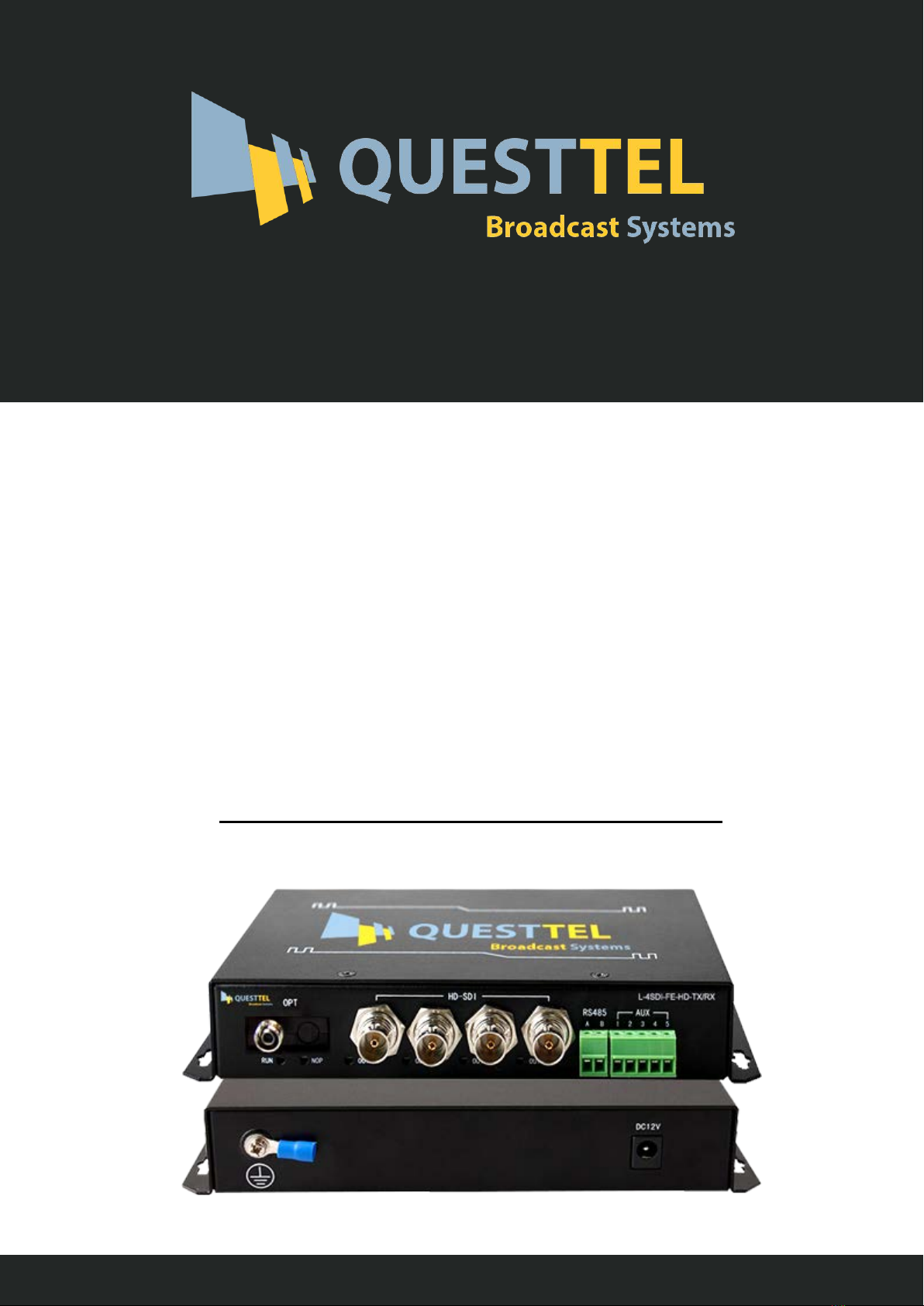
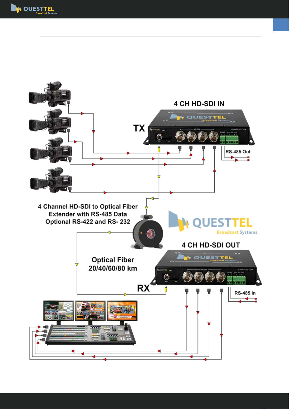
The L-4SDI-FE-HD-TX/RX is a high performance, and reliable, 4-channel HD-SDI video optical transceiver,
which perform real-time, loss-free and high-quality HD-SDI transmission(audio embedded) over an optical
line. Besides, L-4SDI-FE-HD-TX/RX provides one bi-directional RS485 data channel, and optional audio/
contact closure/RS422/RS232 data transmission, which can be widely used in TV live broadcast, high-
definition video conference,
high-definition video monitoring, intelligent transportation system and public security system.
The L-4SDI-FE-HD-TX/RX includes a transmitter named L-4SDI-FE-HD-TX and a receiver named L-4SDI-
FE-HD-RX.
1.2 Feature
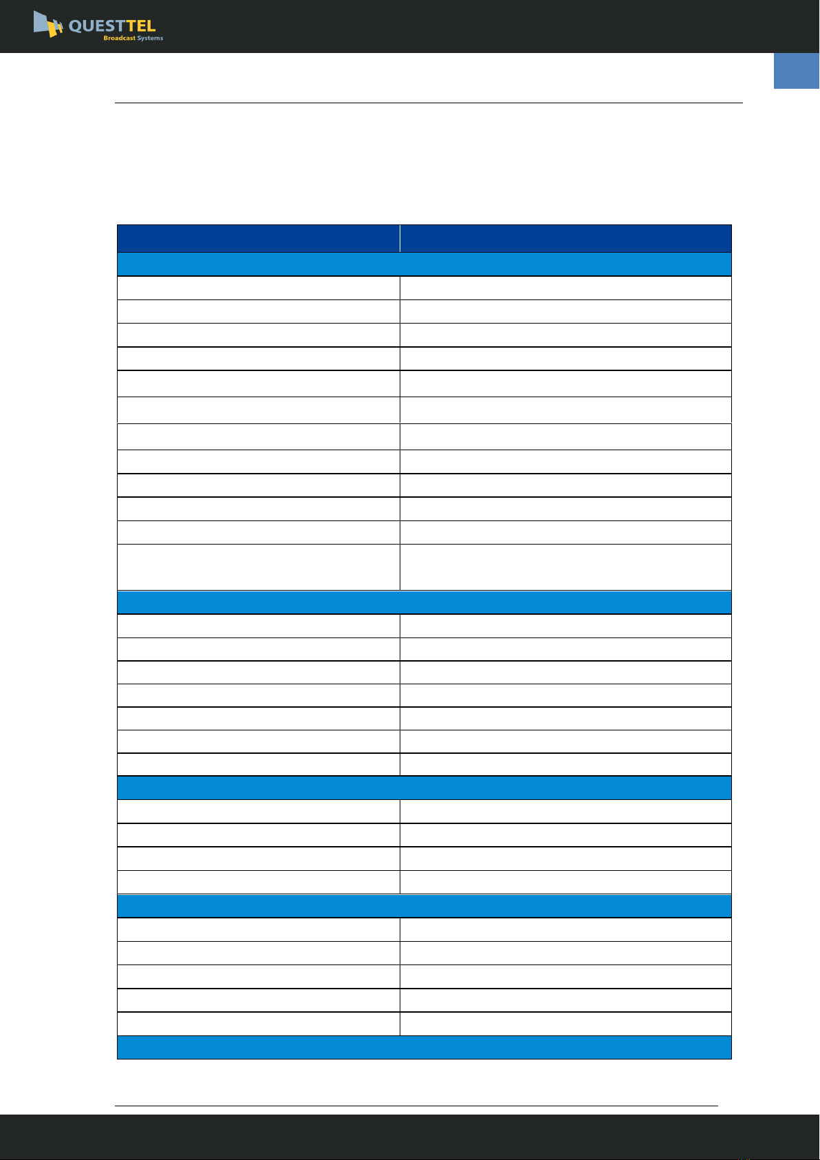
Comply with SMPTE-292M HD-SDI and SMPTE-259M SD-SDI standard, supports 1.485Gb/s and
270Mb/s
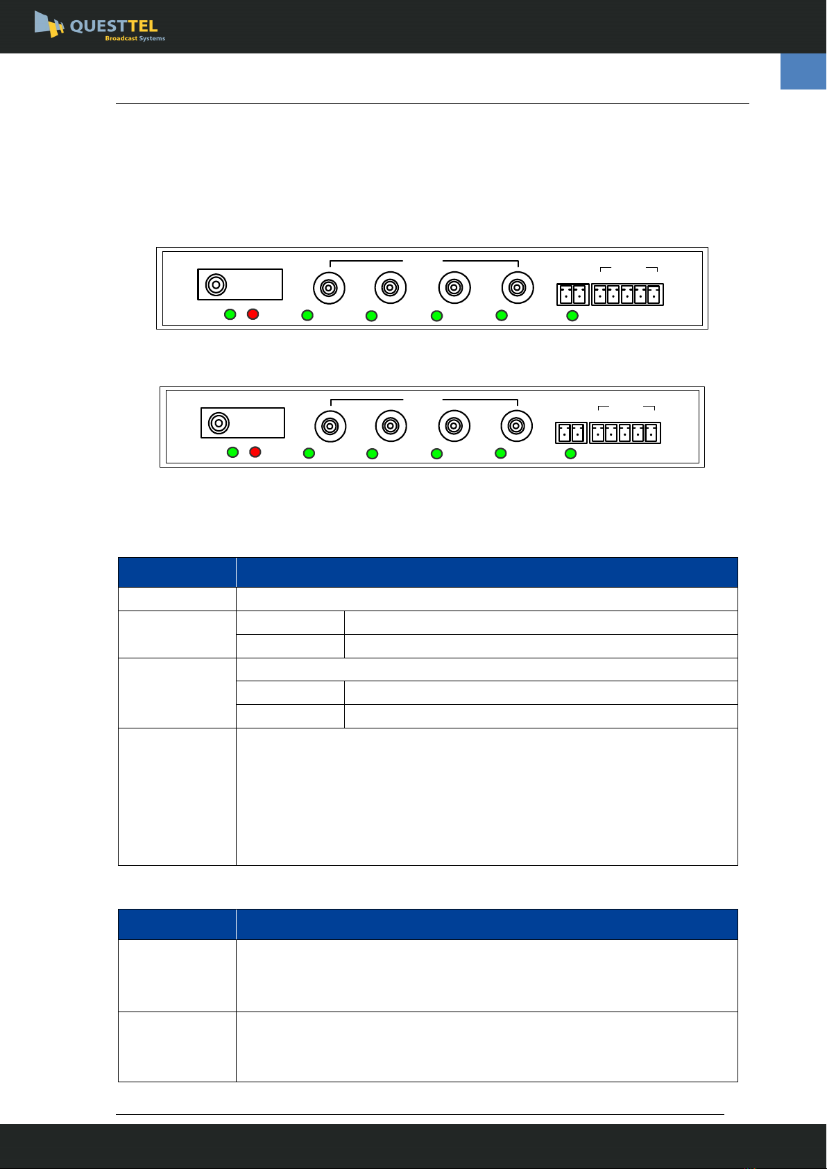
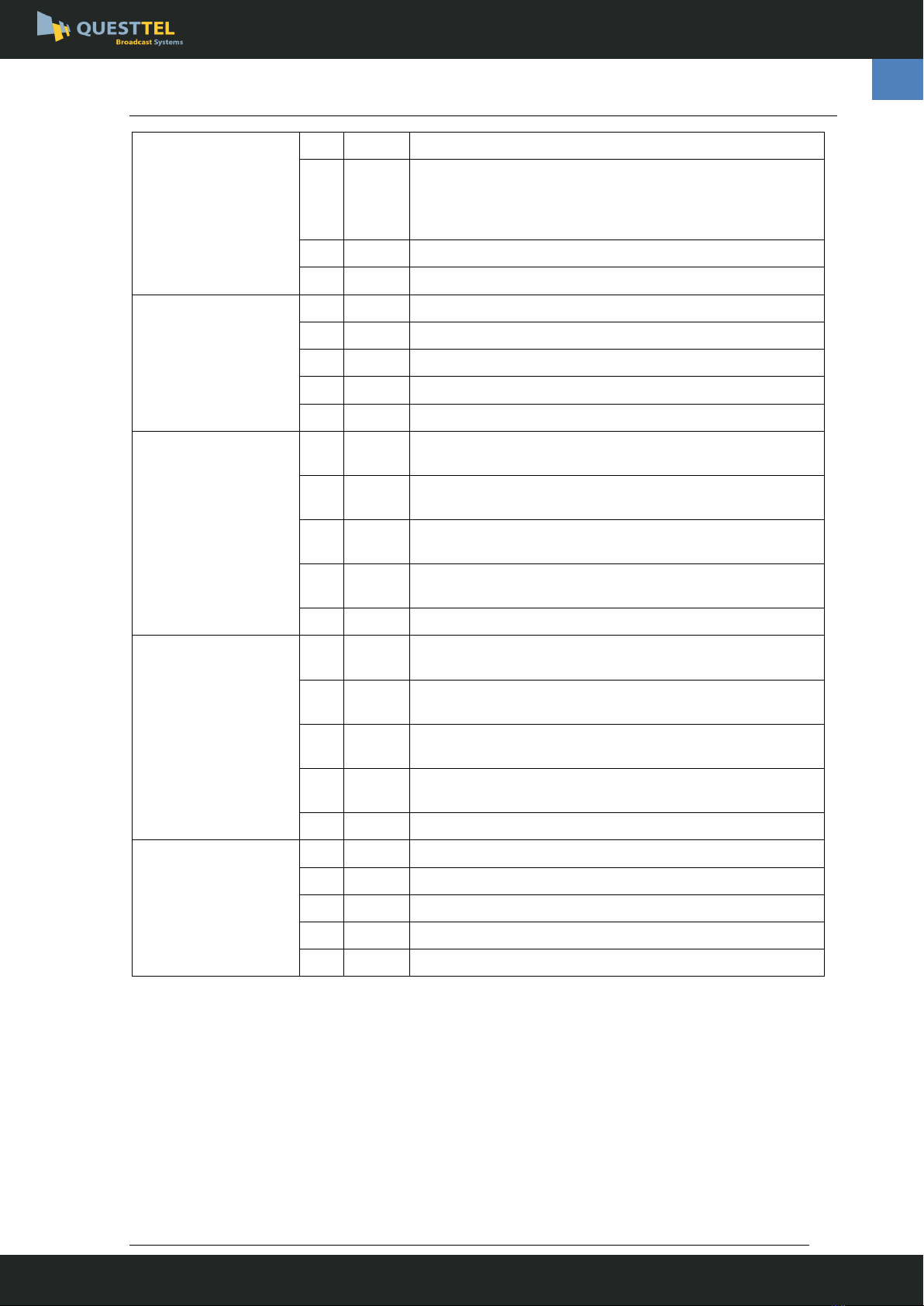
L-4SDI-FE-HD-TX: four HD/SD-SDI input (BNC)
L-4SDI-FE-HD-RX: four HD/SD-SDI output (BNC)
Each SDI channel includes 2-channel audio embedded
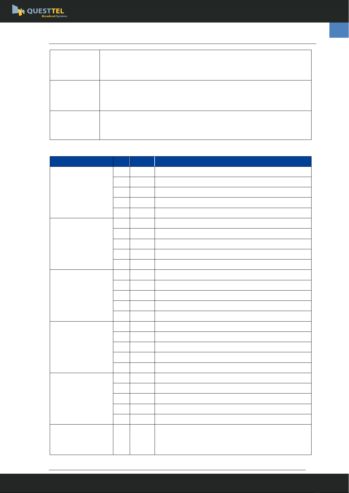
One bi-directional RS485 channel, half duplex, up to 115.2Kb/s baud rate
One auxiliary channel, which can be 2-channel bi-directional audio, or 2-channel unidirectional audio, or
4-channel unidirectional audio, or 2-channel contact closure input/output, or 1-channel bi-directional
RS422 , or 2-channel bi-directional RS232 channel
Supports 1080P@30,25,24, 29.97, 23.98、1080I@60,50,59.94、720P@60,50,30,25,24, 9.94, 29.97, 23.98
and 625i、525i format
With integrated cable equalizer
Embedded ESD and surge protection circuit to prevent damage from static and thunder
With NOP (No optical signal) alarm indications, output status indicator and input lock indicator
With APC circuit to perform stable optical power
www.questtel.com [email protected]
HD/SD-SDI Over Fiber User Manual
L-4SDI-FE-HD-TX-RX

L-4SDI-FE-HD-TX/RX User Handbook
3
1.3 Application
www.questtel.com [email protected]
HD/SD-SDI Over Fiber User Manual
L-4SDI-FE-HD-TX-RX

L-4SDI-FE-HD-TX/RX User Handbook
4
Chapter 2. L-4SDI-FE-HD-TX/RX Desktop Equipment
2.1 Front Panel
OPT
A B
RS485
ACT
IN1 IN2 IN3 IN4
NOP
HD-SDI
AUX
RUN
1 2 3 4 5
Figure 2-1-1 L-4SDI-FE-HD-TX Front Panel
OPT
A B
RS485
ACT
OUT1 OUT2 OUT3 OUT4
NOP
HD-SDI
AUX
RUN
1 2 3 4 5
Figure 2-1-2 L-4SDI-FE-HD-RX Front Panel
Table 2-1-1 Interfaces on L-4SDI-FE-HD-TX/RX front Panel
Name
Description
OPT
Optical interface, bi-directional, adopts FC connector
HD-SDI
IN [1:4]
HD-SDI input 1/2/3/4
OUT [1:4]
HD-SDI output1/2/3/4
RS485
RS485 interface, adopts PHOENIX connector
A
RS485 differential signal A
B
RS485 differential signal B
AUX
One auxiliary channel, which can be 2-channel bi-directional audio, or 2-channel
unidirectional audio, or 4-channel unidirectional audio, or 2-channel contact closure
input/output, or 1-channel bi-directional RS422 , or 2-channel bi-directional RS232
channel. Refer to table 2-1-3 for more.
Note: if the auxiliary channel is used as the audio channel, the embedded audio
channel in the HD-SDI signal will be unavailable.
Table 2-1-2 Indicators on L-4SDI-FE-HD-TX/RX front panel
Name
Description
NOP
Optical signal loss alarm indicator, red.
ON: Optical signal loss is detected at the port.
OFF: the optical port receive normal signal.
RUN
Running indicator, green.
Normal blink: works normally
OFF: Abnormal.
www.questtel.com [email protected]
HD/SD-SDI Over Fiber User Manual
L-4SDI-FE-HD-TX-RX

L-4SDI-FE-HD-TX/RX User Handbook
5
IN [1:4]
The HD-SDI input lock indicator, green.
ON: video input normally.
OFF: video input abnormally.
OUT[1:4]
The SD/HD-SDI output status indicator, green.
ON: output normally.
OFF: output abnormally.
ACT
RS485 link indicator, green.
Blink: There are data transmitting and receiving;
OFF: No data transmit or receive;
Table 2-1-3AUX interface
AUX interface
No.
Name
Description
2-channel
bi-directional audio
(AUX206)
1
AOUT1
Audio channel -1 output
2
AOUT2
Audio channel -2 output
3
G
Ground
4
AIN1
Audio channel -1 input
5
AIN2
Audio channel -2 input
2-channel
unidirectional audio
input
(AUX208)
1
AIN1
Audio channel -1 input
2
AIN2
Audio channel -2 input
3
G
Ground
4
--
--
5
--
--
2-channel
unidirectional audio
Output
(AUX207)
1
AOUT1
Audio channel -1 output
2
AOUT2
Audio channel -2 output
3
G
Ground
4
--
--
5
--
--
4-channel
unidirectional audio
Input
(AUX211)
1
AIN1
Audio channel -1 input
2
AIN2
Audio channel -2 input
3
G
Ground
4
AIN3
Audio channel -3 input
5
AIN4
Audio channel -4 input
4-channel
unidirectional audio
Output
(AUX212)
1
AOUT1
Audio channel -1 output
2
AOUT2
Audio channel -2 output
3
G
Ground
4
AOUT3
Audio channel -3 output
5
AOUT4
Audio channel -4 output
2-channel contact
closure output
(AUX200)
1
NC0
The first channel contact closure output
No alarm: the contact is normally-closed (NC)
Alarm: the contact is open
www.questtel.com [email protected]
HD/SD-SDI Over Fiber User Manual
L-4SDI-FE-HD-TX-RX

L-4SDI-FE-HD-TX/RX User Handbook
6
2
COM0
Command contact of the first channel contact closure
3
NC1
The second channel contact closure output
No alarm: the contact is normally-closed (NC)
Alarm: the contact is open
4
COM1
Command contact of the second channel contact closure
5
--
--
2-channel contact
closure input
(AUX201)
1
K0
The first channel contact closure input
2
COM0
Command contact of the first channel contact closure
3
K1
The second channel contact closure input
4
COM1
Command contact of the second channel contact closure
5
--
--
1-channel
bi-directional RS422/
2-channel
bi-directional RS485
AUX204(T side)
1
TXA(T/
RXA1)
RS422 differential signal A output/ RS485 channel-1
differential signal A
2
TXB(T/
RXB1)
RS422 differential signal B output/ RS485 channel-1
differential signal B
3
RXA(T/
RXA2)
RS422 differential signal A input/ RS485 channel-2
differential signal A
4
RXB(T/
RXB2)
RS422 differential signal B input/ RS485 channel-2
differential signal B
5
G
Ground
1-channel
bi-directional RS422/
2-channel
bi-directional RS485
AUX204(R side)
1
RXA(T/
RXA1)
RS422 differential signal A input/ RS485 channel-1
differential signal A
2
RXB(T/
RXB1)
RS422 differential signal B input/ RS485 channel-1
differential signal B
3
TXA(T/
RXA2)
RS422 differential signal A output/ RS485 channel-2
differential signal A
4
TXB(T/
RXB2)
RS422 differential signal B output/ RS485 channel-2
differential signal B
5
G
Ground
2-channel
bi-directional RS232
(AUX205)
1
TX1
RS232 signal output 1
2
RX1
RS232 signal input 1
3
G
Ground
4
TX2
RS232 signal output 2
5
RX2
RS232 signal input 2
Note1: The AUX interface of L-4SDI-FE-HD-TX and L-4SDI-FE-HD-RX are used in pairs, e.g. if L-4SDI-FE-
HD-TX use 2-channel unidirectional audio output interface, L-4SDI-FE-HD-RX should use 2-channel
unidirectional audio input interface.
Note2: If the auxiliary channel is used as the audio channel, the embedded audio channel in the HD-SDI
signal will be unavailable.
www.questtel.com [email protected]
HD/SD-SDI Over Fiber User Manual
L-4SDI-FE-HD-TX-RX

L-4SDI-FE-HD-TX/RX User Handbook
7
2.2 Rear Panel
DC12V
Figure 2-2-1 L-4SDI-FE-HD-TX/RX Rear Panel
Table 2-2-1 L-4SDI-FE-HD-TX/RX Rear Panel
Name
Description
DC12V
DC 12V power input interface
Adopts AC220V/DC12V power adapter, provides 12V power supply
Protective ground (PGND) screw, connect with the chassis.
www.questtel.com [email protected]
HD/SD-SDI Over Fiber User Manual
L-4SDI-FE-HD-TX-RX

L-4SDI-FE-HD-TX/RX User Handbook
8
Chapter 3. Technical Specification
Table 4-1 Technical Specification
Item
Typical value
HD-SDI Interface
Connector
BNC
Bit rate
1.485Gb/s and 270Mb/s auto adaptive
Impedance
75Ω
Return loss
>15dB
Output level
800mVp-p±10%
Rise and fall time(HD-SDI)
≤270ps
Rise and fall time(SD-SDI)
≤1.50ns
SD-SDI Alignment jitter (1KHz)
≤0.2UI
SD-SDI Timing jitter (10Hz)
<0.2UI
HD-SDI Alignment jitter (100KHz)
≤0.2UI
HD-SDI Timing jitter (10Hz)
<1.0UI
Standard
Comply to SMPTE-292M HD-SDI and SMPTE-259M
SD-SDI standard
Audio Interface (Optional)
Connector
PHOENIX connector
Impedance
Input high-impedance, output 600Ω
Quantization grade
20 bits
Sample frequency
48KHz
Audio input/output voltage
2VP-P
Bandwidth
20Hz~20KHz
Total Harmonic Distortion
0.1%
RS485 Interface
Connector
PHOENIX connector
Baud rate
0~115.2Kb/s
Bit error ratio
<10-9
Duplex
Half-duplex
CONSOLE Interface
Connector
RJ45
Baud rate
19200
bits
8
Stop bit
1
parity check
None
EMU/EMU-EX Interface
www.questtel.com [email protected]
HD/SD-SDI Over Fiber User Manual
L-4SDI-FE-HD-TX-RX

L-4SDI-FE-HD-TX/RX User Handbook
9
Connector
RJ45
Bit rate
10Mb/s or 100Mb/s auto adaptive
Power and Consumption for desktop equipment
Power supply
DC 12V
DC input voltage range
8V~14V
Power consumption
3W±10%
Environment Requirements
Working temperature -30~60℃
Relative Humidity ≤95%, no condensation
Storage temperature -40~85℃
Equipment dimension
Dimension of Rack mounting chassis
(with rack ear)
330mm x 178mm x 482mm
Desktop equipment dimension 180mm x 123mm x 30mm
Note: The optical module is optional for users, the default is 20Km, other long distance needs to be declared when
ordering.
www.questtel.com [email protected]
HD/SD-SDI Over Fiber User Manual
L-4SDI-FE-HD-TX-RX

L-4SDI-FE-HD-TX/RX User Handbook
10
Chapter 4. NTSC/PAL Configuration
The transmitter can automatically detect the HD-SDI/SD-SDI standard of the input video, the receiver supports a
PAL/NTSC dial switch to configure the standard of the output video. When the input video is 1080P@30,25,24,
1080I@60,50, 720P@60,50,30,25,24, the receiver should be configured as PAL; when the input video is
[email protected], 23.98, [email protected], [email protected], 29.97, 23.98, the receiver should be configured as NTSC;
when the input video is 625i, 525i i.e. SD-SDI, both the PAL and NTSC are OK on the receiver.
Figure 5-1 The dial switch for PAL/NTSC standard and embedded audio
When the input video is 625i, 525i i.e. SD-SDI, the audio embedded in the SD-SDI can be tramsmitted to the
receiver transparantly. When the input video is HD-SDI, if there is AUX audio interface, the audio signal is
transmitted between the AUX audio interface and the audio embedded in the HD-SDI is muted; if there is not AUX
audio interface, the audio embedded in the HD-SDI can be transmitted. Only in the last case above, the HD MUTE
dial switch is valid: NORMAL means the audio embedded in the output video is normal, and HD MUTE means the
output video is muted.
www.questtel.com [email protected]
HD/SD-SDI Over Fiber User Manual
L-4SDI-FE-HD-TX-RX

L-4SDI-FE-HD-TX/RX User Handbook
14
Appendix1 Serial management interface(CONSOLE)
Table A-1 Pin description of CONSOLE interface
Pin
Definition
Remarks
PIN1
-
Null
PIN2
-
Null
PIN3
-
Null
PIN4
-
Null
PIN5
-
Null
PIN6
GND
Ground
PIN7
RSNM-IN
Serial network management channel input
PIN8
RSNM-OUT
Serial network management channel output
The CONSOLE cable adopts RJ45 connector at one end to connect the front panel of equipment, and DB9
connector at the other end to connect PC, the diagram is as Fig. A-1-1, Fig.A-1-2 shows:
Figure A-1-1 RJ45 connector
Figure A-1-2 Connection
1
8
8
1
7 RX
8 TX
6 GND
NMU600
2 RX
3 TX
5 GND
PC DB9
www.questtel.com [email protected]
HD/SD-SDI Over Fiber User Manual
L-4SDI-FE-HD-TX-RX

Read before operating equipment.
1. Cleaning - Unplug this product from the wall outlet before cleaning. Do not use liquid cleaners or aerosol cleaners. Use a damp
cloth for cleaning.
2. Power Sources - Use supplied or equivalent UL/CSA approved low voltage DC plug-in transformer.
3. Outdoor Antenna Grounding - If you connect an outside antenna or cable system to the product, be sure the antenna or cable
system is grounded so as to provide some protection against voltage surges and built-up static charges. Section 810 of the
National Electrical Code, ANSI/NFPA No. 70, provides information with respect to proper grounding of the mast and supporting
structure, grounding of the lead-in wire to an antenna discharge unit, size of grounding conductors, location of antenna
discharge unit, connection to grounding electrodes, and requirements for the grounding electrode.
4. Lightning - Avoid installation or reconfiguration of wiring during lightning activity.
5. Power Lines - Do not locate an outside antenna system near overhead power lines or other electric light or power circuits or where
it can fall into such power lines or circuits. When installing an outside antenna system, refrain from touching such power lines or
circuits, as contact with them might be fatal.
6. Overloading - Do not overload wall outlets and extension cords as this can result in a risk of fire or electric shock.
7. Object and Liquid Entry - Never push objects of any kind into this product through openings as they may touch dangerous voltage
points or short out parts, resulting in a fire or electric shock. Never spill liquid of any kind on the product.
8. Servicing - Do not attempt to service this product yourself as opening or removing covers may expose you to dangerous voltage or
other hazards. Refer all servicing to qualified service personnel.
9. Damage Requiring Service - Unplug this product from the wall outlet and refer servicing to qualified service personnel under the
following conditions:
When the power supply cord or plug is damaged.
If liquid spills or objects fall into the product.
If the product is exposed to rain or water.
If the product does not operate normally by following the operating instructions. Adjust only those controls that are
covered by the operating instructions. An improper adjustment of other controls may result in damage and will often
require extensive work by a qualified technician to restore the product to its normal operation.
If the video product is dropped or the cabinet is damaged.
When the video product exhibits a distinct change in performance, this indicates a need for service.
Safety Instructions
www.questtel.com [email protected]
This unit outputs continuous invisible light, which may be harmful to
the eyes; use with caution. For additional safety, plug the attached
dust caps into the optical transceivers when the fiber optic cable is
unplugged. Direct viewing into optical connectors should be avoided at all
times!
WARNING!
This manual suits for next models
1
Table of contents
Other Questtel Transceiver manuals