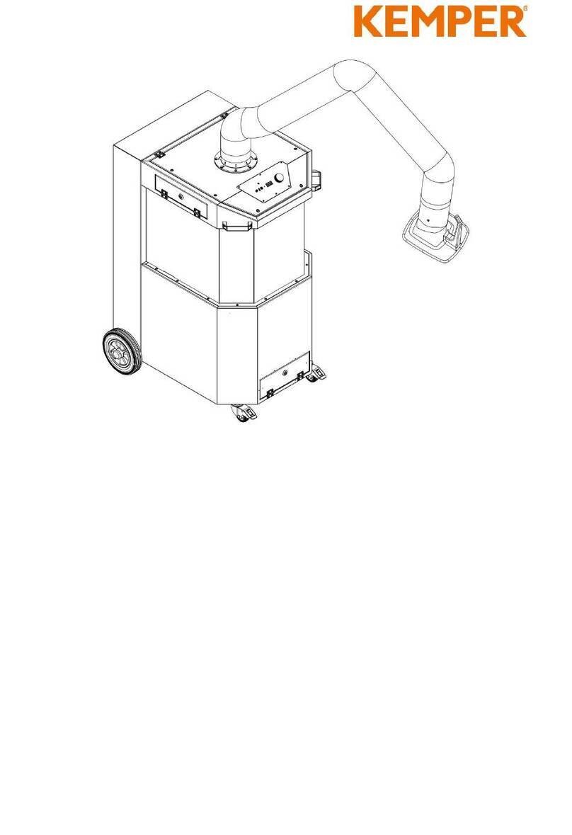
Kemper Mini-Weldmaster User manual

Mini-Weldmaster
3-Phasen Drehstrom
Mini-Weldmaster
3 Phase, AC Operated
Mini-Weldmaster
Triphasé
Mini-Weldmaster
trifásico
Mini-Weldmaster
Trojfázov˘ stfiídav˘ proud
Mini-Weldmaster
trójfazowy
Mini-Weldmaster
рёхфазный, переменный ток
Art-Nr. 150 0151


A. Verwendung
Der KEMPER Mini-Weldmaster wird vorwiegend zum punktförmigen Absaugen von Schweißrauch
eingesetzt. Die schadstoffhaltige Luft wird aus dem Atembereich des Schweißers entfernt.
Die abgesaugten Schadstoffe (Partikel) werden in dem Filtereinsatz abgeschieden.
Die so gereinigte Luft wird dem Raum wieder zugeführt. Auf diese Weise werden bessere
und gesündere Arbeitsbedingungen geschaffen.
B. Wirkungsweise
Die schadstoffhaltige Luft wird mit Absaugdüsen, die mit Magneten schräg oberhalb
der Schweißstelle angebracht werden, aus dem Atembereich des Schweißers entfernt.
Über Verbindungsschläuche gelangt sie in den Mini-Weldmaster.
Hier werden die Schadstoffe mechanisch abgeschieden.
Die Filterung erfolgt in drei Stufen:
1. Vorfilter zum Abfangen grober Partikel
2. Schwebstofffilter zur Abscheidung feinster Partikel bis zu einem Durchmesser
von unter 0,1 Mikron (Abscheidegrad > 99,997 % DOP Test)
3. Auf Wunsch ist für den Mini-Weldmaster auch ein Aktivkohlefilter zur Adsorption der Gase
und Geruchsstoffe erhältlich. Dieses wird unterhalb des Schwebstofffilters in das Gerät
eingelegt und filtert dann auch die gasförmigen Schadstoffe aus der angesaugten Luft heraus.
Die so gereinigte Luft wird von zwei Turbinen angesaugt und über ein Ausblasgitter in den
Arbeitsraum zurückgeführt. Sie kann normalerweise dem Raum wieder zugeführt werden.
Dieses ist nicht zulässig bei Schweißrauch mit krebserregenden Anteilen, z.B. beim Verschweißen
von Edelstählen (vgl. TRGS 560). Soll trotz des hohen Abscheidegrades die gereinigte Luft nicht in
den Arbeitsraum zurückgeführt werden, so kann sie mittels eines Übergangsstückes und eines
entsprechenden Schlauches nach draußen geleitet werden.
C. Sicherheitshinweise
Achtung:
Beim Gebrauch von Elektrogeräten sind zum Schutz gegen elektrischen Schlag,
Verletzungs- und Brandgefahr folgende grundsätzlichen Sicherheitsmaßnahmen zu beachten!
Lesen und beachten Sie dieses Hinweise, bevor Sie das Gerät benutzen.
• Bewahren Sie diese Betriebs- und Wartungsanleitung gut auf
• Setzen Sie das Gerät nicht zum Absaugen von leicht entzündlichen bzw. explosiven Gasen ein
• Setzen Sie das Gerät nicht zum Absaugen von aggressiven Medien ein
• Schützen Sie das Anschlusskabel vor Hitze, Öl und scharfen Kanten
• Achten Sie darauf, dass das Gerät sicher steht
• Verwenden Sie nur Original-Ersatzfilter
• Betreiben Sie das Gerät nicht ohne Filtereinsatz
•Verunreinigungen in der angesaugten Luft führen zur Zerstörung der Turbinen!
1

2
• Vor dem Öffnen des Gerätes Netzstecker ziehen
• Die Belüftungs- und Ausblasschlitze dürfen nicht verdeckt werden
• Schützen Sie das Gerät vor Feuchtigkeit
• Keine wässrigen Dämpfe einsaugen
C-1 Thermischer Überlastschutz
Die beiden Saugturbinen sind serienmäßig über einen thermischen Überlastschutz abgesichert,
der die Aggregate bei Überhitzung automatisch abschaltet und so zuverlässig ein Durchbrennen
der Motorabwicklungen verhindert.
Achtung:
Nach dem Abkühlen schalten sich die Saugturbinen wieder ein!
D. Inbetriebnahme
D-1 Aufbau und Anschluss
Die entsprechende Absaugdüse mit Magnetfuß bzw. das Schweisserschutzschild mit integrierter
Absaugung über den Verbindungsschlauch an das Oberteil des Mini-Weldmasters anschließen.
Absaugdüse so positionieren, daß sie sich etwa 10 cm oberhalb der Schweißstelle befindet.
Mini-Weldmaster an das Stromnetz anschließen.
Achtung:
Angaben auf dem Typenschild beachten!
Nur bei Verwendung einer Start-Stop-Automatik (Zubehör):
Stecker der Start-Stop-Zange in die Buchse links auf der Bedientafel einstecken und durch
leichtes Verdrehen sichern.
Durch den Einsatz der Start-Stop-Automatik wird erreicht, das die Absauganlage nur während der
reinen Schweißzeit (Lichtbogenzeit) und einer gewissen Nachlaufzeit in Betrieb ist. Hierfür wird ein
Fühler, die Start-Stop-Zange, am Massekabel des Schweißgerätes befestigt. Auf diese Weise wird
der Elektronik mitgeteilt, ob gerade geschweißt wird oder nicht. Bei Beginn des Schweißvorganges
schaltet sich die Absauganlage automatisch ein. Nach Beendigung des Schweißvorganges läuft
die Anlage noch kurze Zeit nach, um ein Takten z.B. beim Heften von Werkstücken zu vermeiden.

3
D-2 Bedientafel
Geräteschalter
An diesem Schalter wird das Gerät eingeschaltet.
Filterüberwachung
Der Sättigungsgrad des Hauptfilters wird elektronisch überwacht und
über die Kontrollleuchten angezeigt.
Grüne Lampe: Filter in Ordnung
Orange Lampe: Sättigungsgrad des Filters 50 %
Rote Lampe: Filter gesättigt, Filterwechsel erforderlich
Buchse(n) für Start-Stop-Zange (Zubehör)
• Stecker der Start-Stop-Zange in die Buchse links auf der Bedientafel des Filtergerätes
einstecken und durch leichtes Verdrehen sichern.
• Start-Stop-Zange am Massekabel des Schweißgerätes befestigen.
• Das Gerät arbeitet nun automatisch in Abhängigkeit vom Schweißvorgang.
E. Wartung
E-1 Filterwechsel
Aufgrund des mechanischen Filtereinsatzes ist gewährleistet, das mehr als 99,997 % der
abgesaugten Schadstoffe (Partikel) im Filter verbleiben. Das gilt auch dann, wenn der
Filtereinsatz ganz oder teilweise gesättigt ist.
Mit zunehmender Sättigung des Filtereinsatzes sinkt jedoch die Absaugleistung des Filtergerätes.
Vorgehen beim Filterwechsel:
• Netzstecker ziehen.
• Die seitlichen Druckknöpfe am Gehäusedeckel mit den Handballen
zusammendrücken und so den Deckel öffnen.
• Vorfiltereinsatz und Schwebstofffilter entnehmen.
• Neues Schwebstofffilter einsetzen.
Achtung:
Filter nicht reinigen! Ausklopfen oder Ausblasen mit Druckluft führt zur
Zerstörung des Filtermediums. Schadstoffe gelangen in die Raumluft.
1
2
3

4
E-2 Vorfiltereinsatz
Der Vorfiltereinsatz ist mit einer auswechselbaren Filtermatte ausgerüstet.
Durch regelmäßigen Wechsel dieser Filtermatte lässt sich die Standzeit
des nachfolgenden Hauptfilters erheblich verlängern. Sie sollte deshalb
in regelmäßigen Zeitabständen (z.B. wöchentlich) gewechselt werden.
Hierbei wie folgt vorgehen:
• Drahtbügel herausnehmen. (Abb. 3)
• Gebrauchte Filtermatte entfernen und neue Filtermatte einsetzen.
• Filtermatte mit dem Drahtbügel sichern.
E-3 Wartung der Turbineneinheit
Die Saugturbine wird über einen Flachriemen durch einen Kurzschlussankermotor angetrieben.
Als Grundplatte dient eine abgewinkelte Stahlplatte mit 6 Befestigungsbohrungen.
Die riemengetriebene Saugturbine benötigt keine Wartung.
Bei Ausfall des Flachriemens (Lebensdauer je nach Einsatzbedingung und Belastung
ca. 3.000 bis 8.000 Betriebsstunden), ist darauf zu achten, das der neue Flachriemen mit
der erforderlichen Vorspannung von 2 % aufgezogen wird.
Zu diesem Zweck markiert man auf dem Riemen im ungespannten Zustand eine Strecke
von 100 mm und zieht ihn auf die Riemenscheibe auf. Ist diese Markierung dann um 2 %
d.h. auf 102 mm auseinandergezogen, so ist die Riemenspannung in Ordnung.
Andernfalls ist der Achsenabstand durch Lösen der Befestigungsschrauben vom Motor
und Turbineneinheit entsprechend zu verändern.
Abbildung 3

5
F. Technische Daten
G. Ersatzteil-Liste
Anschlussspannung
Stromart
Stromaufnahme
Motorleistung
Volumenstrom
Max. stat. Pressung
Vorfiltermatte
Schwebstofffilter
Gehäuseabmessungen
Gewicht
3 x 400 V, 50 Hz
3 phasig
2,8 A
1,1 kW
270 m3/h
11.000 Pa
305 x 305 mm
305 x 305 x 150 mm
Breite 340 mm
Tiefe 450 mm
Höhe 620 mm
50 kg
Bezeichnung
Vorfiltermatten (10er-Set)
Schwebstofffilter
Standfuß
Saugturbine 400 V
Kontrollleuchte, grün
Kontrollleuchte, orange
Kontrollleuchte, rot
Geräteschalter
Temperaturüberwacher
Steuereinheit
Blindstopfen
Umluft bzw. Abluftschlauch
Mit zwei Ansaugstutzen
2,5 m
5,0 m
10,0 m
Stutzen für Schlauch
Kupplung für Schlauch
Artikel-Nr.
109 0034
109 0009
48 500
19 501 100
360 0017
360 0560
360 0015
360 0144
360 0613
917 30 000 05
106 0070
93 070 004
93 070 005
93 070 006
106 0076
106 0077
Pos.
1
2
3
4
5
6
7
8
9
10
11
12
13a
13b

6
EG-Konformitätserklärung
nach Maschinenrichtlinie 98/37/EWG
Der Hersteller:
KEMPER
GmbH
Von-Siemens-Str. 20
D-48691 Vreden
erklärt, dass die nachfolgende Maschinen (oder Baugruppe, Maschinenteil usw.):
Bezeichnung; Name Mini-Weldmaster 3-Phasen Drehstrom
Art.-Nr. 91 730 100, 91 731 100
folgenden einschlägigen Bestimmungen entspricht:
98/37/EWG Maschinensicherheits- Richtlinie
89/336/EWG EMV - Richtlinie
73/23/EWG Niederspannung - Richtlinie
93/68/EWG Kennzeichnung - Richtlinie
Angewendete harmonisierte Normen, insbesondere:
EN 292 Teil 1 und Teil 2, EN 294,
EN 349, EN418, EN 983 Sicherheit von Maschinen
EN 1050 Sicherheit von Maschinen - Leitsätze
zur Risikobeurteilung
EN 60204 -1:1998-10 Elektrische Ausrüstung von Maschinen
EMVG Gesetz über die elektromagnetische
Verträglichkeit von Maschinen
EN 50081 Teil 2 Fachgrundnorm Störaussendung
EN 50082 Teil 2 Fachgrundnorm Störfestigkeit
Angewendete nationale technische Spezifikationen, insbesondere:
VDE 0100 Errichten von Niederspannungsanlagen
VDE 0113 Elektrische Ausrüstung von Maschinen – Erläuterungen
zu EN 60204-1:1998-10
UVV BGV A1 Unfallverhütungsvorschrift: Grundsätze der Prävention
BGR 500 2.26 Schweißen, Schneiden und verwandte Verfahren
DIN 45635 Geräuschmessung an Maschinen
Diese Erklärung verliert ihre Gültigkeit, wenn eine nicht mit dem Hersteller in schriftlicher Form
abgestimmte Änderung vorgenommen wird.
VREDEN, 17.02.1998
KEMPER
GmbH
Dipl.-Ing.M. Könning
(Leiter der Technik)

7
A. Application
The KEMPER Mini-Weldmaster is primarily used for source extraction of welding smoke.
The contaminated air is removed from the breathing zone of the welder. The extracted
harmful substances (particles) are trapped by the filter insert. The cleaned air is then
reurned to the room. The result is a better an healthier work environment.
B. Function
The contaminated air is removed from the breathing zone of the welder by exhaust nozzles
which are placed with magnets in an angle above the item to be welded. The contaminated
air flows through the flexible hoses and into the Mini-Weldmaster. There the impurities are
mechanically filtered out.
Filtering is accomplished in three stages:
1. The pre-filter removes coarse particles
2. The particulate filter removes even the smallest particles, down to under 0,1 micron
in diameter (efficiency greater than 99,997 % DOP-Test)
3. The Mini-Weldmaster is also available with an activated charcoal filter (optional).
This filter is inserted underneath the unit´s main filter (HEPA filter).
It is used to adsorb the hazardous gases and odors from the air stream.
The cleaned air is extracted by two turbines and then returned to the work place
through an exhaust grid. It can be returned usually to the workplace.
This is not allowed in case of welding smoke with a share of carcinogenic particles,
c. g. when welding highgrade steel (see TRGS 560).
However, in spite of the high efficiency, if you do not want to return the cleaned air
to the workplace, it can be exhausted outside using an adapter and the respective hose.
C. Safety Precautions
Caution:
When using electrical devices, the following basic safety measures must be followed
to prevent shock, inury or fire.
Read and follow these instruction before using the filter unit.
• Keep this Installation and Operating Manual handy
• Do not use the unit to extract easily flammable or explosive gases
• Do not use the unit to extract crrosive substances
• Do not expose the connecting cable to heat, oil or sharp edges
• Make sure the unit stands stable and secure
• Use only original equipment filters
• Do not operate the unit without filter inserts
•Contaminants in the extracted air will destroy the blower!

8
• Always unplug unit before opening it
• Never cover intake or exhaust openings
• Protect the unit from dampness
• Do not extract vapors containing water (steam).
C-1 Thermal Overload Protection
The blower is equipped with factory-installed thermal overload protection.
This automatically switches the unit off in case of overheating, thereby
preventing burn-out of the motor windings.
Caution:
After cooling down, the blowers will switch on again automatically!
D. Start Up Instructions
D-1 Installation and Connection
Connect the respective exhaust nozzle with magnetic foot, or the protective shield
with integrated extraction, with the connecting hose to the top of the Mini-Weldmaster.
Position the exhaust nozzle so that it is about 10 cm (4 inches) above the welding location.
Connect the Mini-Weldmaster to he power supply.
Caution:
Comply with information on the unit´s nameplate!
For applications using the automatic Start/Stop feature (accessory):
Insert the plug of the Start/Stop clamp into the socket on the left side of the control panel.
Turn slightly to secure it.
Installing the automatic Start/Stop module makes it possible to operate the filter unit only during
the true welding time (arcing time) plus an preset run-on time. For this,a sensor, the automatic
Start/Stop clamp, is fastened to the grounding cable of the welding unit. In this way, the electronic
unit receives a message whether welding is occurring or not. At the beginning of the welding
process, the unit is switched on automatocally. When welding is completed, the unit continues
to operate for a short time in order to avoid constant on/off cycling, such as during tack welding.

9
D-2 Control Panel
Main Switch
This switch is used to turn the unit on.
Filter Monitor
The saturation level of the main filter is electronically monitored and displayed by control lights.
Green light: Filter OK
Amber light: Saturation of filter exceeds 50 %
Red light: Filter saturated, Filter must be changed
Socket for Start-Stop clamp (Accessory)
• Insert the plug of the Start-Stop clamp into the left socket on the control panel
of the filter unit. Turn slightly to secure it.
• Fasten the Start-Stop clamp to the grounding (neutral) cable of the welding unit.
• The unit is now ready to operate automatically, according to the welding process.
E. Maintenance
E-1 Replacing Filters
The mechanical filter insert assures that more than 99,997 % of the extracted pollutants
(particles) remain trapped in the filter. This is also true whether th filter insert is completely
or partially saturated. However, as the filter insert becomes increasingly saturated,
the exhaust capacity of the filter unit.
Filter changing procedures:
• Unplug unit from power supply
• Press the side press buttoms of the housing cover with the thenar and open the cover.
• Remove pre-filter insert and particulate filter.
• Insert new particulate Filter.
Caution:
Do not clean filter. Cleaning the filter by shaking or by using compressed air destroys
the filter. The contaminants reenter the work place air!
1
2
3

10
E-2 Pre-filter Insert
The pre-filter is equipped with a replaceable filter insert mat.
Changing this filter mat at regular intervals greatly increases the operation life
of the subsequent main filter.
Therefore it should be changed at regular intervals (for example, weekly).
To change the mat, follow these steps:
• Pull out the wire fasteners (see illustration 3)
• Take out the old filter mat and replace it with the new one.
• Secure the new filter mat with the wire fasteners.
E-3 Maintenance of Blower unit
The blower unit is driven by a flat transmission belt from a squirrel cage induction motor.
Both are mounted to an angular steel bracket with six mounting. The belt driven blower
unit generally does not need maintenance. When the flat belt breaks (usually not until after
3.000 to 8.000 hours of operation). The new belt must be mounted with an initial tension
of 2 %. To achieve the correct tension, mark the new belt at a distance of 100 mm before
you mount it. Then mount it on the pulley. If the distance marked increases to 102 mm (2 %),
then the belt tension is correct. If not, the axial distance can be changed by loosening the
mounting screw of either the motor or the blower, as required.
Illustration 3

11
F. Technical Data
G. Spare Parts List
Voltage
Current Type
Power Consumption
Motor Power
Exhaust Capacity
Max. static Pressure
Pre-filter mat
Particulate filter
Housing
Weight
3 x 400 V, 50 Hz
3 phasig
2,8 A
1,1 kW
270 m3/h
11.000 Pa
305 x 305 mm
305 x 305 x 150 mm
Width 340 mm
Depth 450 mm
Height 620 mm
50 kg
Description
Pre-Filter mats (10 per set)
Particulate filter
Foot
Blower 400 V
Monitor light, green
Monitor light, amber
Monitor light, red
Main unit switch
Temperature monitor
Speed control
Blind cover
Exhaust hose with
two connector stubs
8 ft.
16 ft.
33 ft.
Connection piece
Coupler for hose
Part No.
109 0034
109 0009
48 500
19 501 100
360 0017
360 0560
360 0015
360 0144
360 0613
917 30 000 05
106 0070
93 070 004
93 070 005
93 070 006
106 0076
106 0077
Pos.
1
2
3
4
5
6
7
8
9
10
11
12
13a
13b

12
European Community Declaration of Conformity
According to the European community machine standard 2006/95/EG
The manufacturer:
KEMPER
GmbH
Von-Siemens-Str. 20
D-48691 Vreden
confirms that the following machines (or building group, machine part etc.):
Description; Name Mini-Weldmaster
3 Phase, AC Operated
Part. No. 91 730 100, 91 731 100
Corresponds to the following relevant regulations:
98/37/EWG Machine safety guideline
89/336/EWG EMV - Guideline
73/23/EWG Low-voltage - guideline
93/68/EWG Marking - guideline
Applicable harmonized standards, especially:
EN 292 part 1 and part 2, EN 294,
EN 349, EN418, EN 983 Security of machines
EN 1050 Security of machines - guiding
principles for risk evaluation
EN 60204 -1:1998-10 Electrical equipment of machines
EMVG Law referring to the electromagnetic
Compatibility of machines
Part 2 of EN 50081 Specialized basic standard breakdown
Part 2 of EN 50082 Specialized basic standard noise immunity
Applicable national and technical specification, especially:
VDE 0100 construction of low-voltage plants
VDE 0113 Electrical equipment of machines –
complies to EN 60204-1:1998-10
UVV BGV A1 Regulations for the prevention of accidents:
Principles of prevention
BGR 500 2.26 Weld, cuts and related procedures
DIN 45635 Noise levels at machines
This explanation loses its validity, if a change not co-ordinated with the manufacturer
in written form is made.
VREDEN, February 17th, 1998
KEMPER
GmbH
Dipl. - Engineer M. Könning
(Chief technical engineer)

13
A. Emploi
Le Mini-Weldmaster est surtout utilisé pour l'aspiration ponctuelle des fumées de soudre.
L'air pollué est éliminé du rayon respiratoire du soudeur. Les émanations nocives aspi rées
(particules) sont retenues dans le filtre. L'air purifié est reconduit dans l'atelier. De ce fait,
il est possible d'améliorer et d'assainir considérablement les conditions de travail.
B. Fonctionnement
L'air pollué est éliminé du rayon respriatoire à l'aide de buses d'aspiration, fixées en position
inclinée, à l'aide d'aimants, au-dessus du point de soudure. Il est mené au Mini-Weldmaster
par des flexibles de raccordement. Là la séparation des particules se fait mécaniquement.
La filtration se fait en trois étapes:
1. Préfiltre pour la réception des particules grossières
2. Filtre à particules pour retenir les particules très fines, jusqu'en dessous
de 0,1 micron de diamètre (degré de séparation supérieur à 99,997 % Test DOP).
3. Sur demande, le Mini-Weldmaster peut être équipé d'un filtre à charbon actif pour adsorption
des gaz et odeurs. Celui-ci est placé en-dessous du filtre à particules.
L'air purifié est aspiré par deux turbines et reconduit dans l'atelier par une grille de reject.
Il peut être rejeté normalement dans l'atelier. Ce n'est pas permis en cas de fumées de soudure
avec un contenu cancérigéne, par exemple en soudant des aciers fins (voir TRGS 560).
Dans le cas où l'air devrait être évancué à l'extérieur, il existe la possibilité de brancher un tuyau
de refoulement à cet effect.
C. Consignes de sécurité
Attention:
Lors de l'utilisation d'appareils électriques, il est nécessaire de prendre les Mesures
de sécurité suivantes, afin d'éviter les blessures ou brûlures.
Lisez et suives ces indications avant d'utiliser l'appareil.
• Conservez cette notice d'emploi et d'entretien
• N'utilisez pas ces appareils pour l'aspiration de gaz facilement inflammables ou explosifs
• N'utilisez pas ces appareils pour l'aspirtion des émanations agressives
• Préservez le câble de la chaleur, de l'huile ou d'objets coupants
• Assurez-vous que l'appreil soit posé stablement
• N'utilisez que des filtres de rechange d'origine
• Ne faites pas fonctionner l'appareil sans filtres
•Les impuretés contenues dans l'air aspiré abiment les turbines!
• Débrancher l'appreil avant ouverture
• Ne pas boucher les ouvertures d'aération ou les fentes de rjet
• Protéger l'appareil de l'humitdité
• Ne pas aspirer des vapeurs à forte contenance d'eau.

14
C-1 Protection de surcharge thermique
Les deux turbines sont protégées de série par un détecteur de surcharge thermique,
les arrêtant automatiquement en cas de surchauffe, évitant ainsi de griller les bobinages du moteur.
Attention:
Après refroidissement les turbines se mettent automatiquement en marche!
D. Mise en marche
D-1 Montage et branchement
La buse d'aspiration à pied magnétique ou le masque de soudage à aspiration intégrée
est à raccorder par l'intermédiaire du flexible à partie supérieure du Mini-Weldmaster.
Les buses d'aspiration sont à positionner à 10 cm env. audessus du point de soudage.
Brancher l'appareil sur le réseau électrique.
Attention:
Tenir compte des indications protées sur la plaque signalétique!
En cas d'utilisation du start-stop automatique (accessoires)
Brancher la prise du start-stop sur la douille prévue à cet effet à gauche sur le tableau
de commande et la bloquer.
Le but de la mise en place d'un start-stop automatique est le fait que l'installation d'aspiration
ne fonctionne effectivement que pendant la durée réelle du dage (durée de l'arc électrique) et
pendant un temps de poursuite règlable. Pour cela une tenaille de start-stop est fixée au câble
de masse de l'appareil à souder. Par là, l'électronique est informée si un soudage est en cours
ou non. Dès que le soudage commence, l'aspiration se met automatiquement en marche.
A la fin du soudage soudage, l'installation d'aspiration continue encore pendent un moment pur
èliminer totalement les èmanations nocives. Ce temps de poursuite est règlable sur le module
start stop.

15
D-2 Tableau de commande
Interrupteur
Sur ce interrupteur, l'appareil est mis en marche.
Contrôle de saturation des filtres
Le degré de saturation du filtre principal est surveillé électroniquement
et iniqué par des témoins lumineux.
Témoin vert: Filtre en bon état
Témoin orange Filtre saturé à 50 %
Témoin rouge: Filtre saturé, remplacement nécessaire
Prise pour pince start-stop (accessoire)
• Brancher le règulateur sur la prise se trouvant à gauche sur le tableau de commande
et la bloquer.
• Fixer la pince start-stop sur le câble de masse du poste à souder
• L'appareil travaille maintenant automatiquement, en dèpendance du soudage.
E. Entretien
E-1 Remplacement des filtres
En raison de la filtration mécanique, il est garanti que 99,997 % des substances nocives aspirées
(particules) restent dans le filtre. Il en est de même quand le filtre est partiellement ou totalement
saturé. Toutefois, au fur e à mesure de la saturation des filtres, la capacité d'aspiration.
March à suivre:
• Débrancher
• Poussez les boutons-poussoir situés au côté du chapeau du carter avec votre main
et ouvrez le chapeau.
• Oter le préfiltre et le filtre à deux étages .
• Remplacer par de nouveaux.
Attention:
Le nettoyage du filtre n'est pas possible. Il risquerait d'être abîmé et perdrait
donc son efficacité. Ceci entraînerait le retour de l'air pollué dans l'atelier.
1
2
3

16
E-2 Cadre de préfiltre
Les nattes de préfiltre sont placées dans un cadre métallique. Par un remplacement régulier
de cette natte, la durée de vie du filtre principal est considérablement augementée.
Il est donc recommandé de la changer régulièrement (par ex. toutes les semaines).
Marche à suivre:
• Oter les baleines métalliques (voir illustration 3).
• Enlever la natte usagée et y remeetre une nouvelle.
• La fixer par les baleines.
E-3 Entretien de la turbine
La turbine est entraînée par un moteur à courroie plate. La plaque de base est une plaque d´acier
avec 6 trous de fixation. La turbine entraînée par courroie ne nécessite pas d´entretien. En cas de
rupture de la courroie avec une prétension de 2 %. Pour ce faire, il faut marquer une distance de
100 mm sur la courroie détendue et la monter sur la poulie. Si, aprés montage, le marquage est
allongé de 2 %, soit à 102 mm, la tension est bonne. Dans cas contraire, el est néccessaire
d´augmenter en conséquence la distance entre axes en défainsant les vis de fixation du moteur
et de la turbine.
Illustration 3

17
F. Données Techniques
G. Liste de piéces de rechange
Tension d’alimentation
Courant
Intensité
Puissance moteur
Capacité d’aspiration
Pression statique max.
Préfiltre
Filtre à particules
Dimensions de l’appareil
Poids
3 x 400 V, 50 Hz
3 ph
3,6 amp
1,75 hp
270 cfm
44" WC
12" x 12"
12" x 12" x 6"
Largeur 13 3/8"
Profondeur 17 1/2"
Hauteur 25"
110 Ibs
Article
Nattes de préfiltre (carton de 10)
Filtre à particules
Pieds
Turbine 400 V
Témoin de contrôle, vert
Témoin de contrôle, orange
Témoin de contrôle, rouge
Interrupteur
Contrôleur de température
Unité de commande
Couvercle
Flexible d’aspiration ou de
refoulement avec 2 manchos
2,5 m
5,0 m
10,0 m
Manchon pour tuyau
Accoplement pour tuyau
Réf.
109 0034
109 0009
48 500
19 501 100
360 0017
360 0560
360 0015
360 0144
360 0613
917 30 000 05
106 0070
93 070 004
93 070 005
93 070 006
106 0076
106 0077
Pos.
1
2
3
4
5
6
7
8
9
10
11
12
13a
13b

18
DECLARATION DE CONFORMITE CE
Selon directive 2006/95/EG relative aux machines
Fabricant:
KEMPER
GmbH
Von-Siemens-Str. 20
D-48691 Vreden
déclare que la construction des appareils suivants:
Dénomination Mini-Weldmaster Triphasé
Type 91 730 100, 91 731 100
est conforme aux réglementations suivantes:
98/37/CE Directive relative à la sécurité des machines
89/336/CE Compatibilité électromagnétique
73/23/CE Réglementation basse tension
93/68/CE Réglementation des marquages
- aux réglementations des normes harmonisées, en particulier:
EN 292 parties 1 et 2, EN 294,
EN 349, EN418, EN 983 Sécurité des machines
EN 1050 Sécurité des machines – directives
d’évaluation des risques
EN 60204 -1:1998-10 Equipement électrique des machines
EMVG Réglementation sur la compatibilité
électromagnétique des machines
EN 50081 partie 2 Norme de base sur les effets parasites
EN 50082 partie 2 Norme de base sur la résistance aux parasites
- aux spécifications techniques nationales, en particulier:
VDE 0100 Mise en place d’installations basse-tension
VDE 0113 Equipement électrique de machines – réf.
à EN 60204-1:1998-10
UVV BGV A1 Prévention des accidents : bases de prévention
BGR 500 2.26 Soudage, coupage et procédés apparentés
DIN 45635 Mesure de niveau sonore
Cette déclaration perd sa validité si une modification a été faite sans accord écrit du constructeur.
VREDEN, 07.01.2007
KEMPER
GmbH
Dipl.- Ing. M. Könning
(Responsable technique)
Table of contents
Languages:
Other Kemper Welding System manuals
Popular Welding System manuals by other brands

Gude
Gude MIG 192/6K Translation of the original instructions

WELDPRO
WELDPRO CUT60Hsv Operator's manual

EWM
EWM T 4.06 - AC/DC Smart 2.0 operating instructions

WELDING INDUSTRIES
WELDING INDUSTRIES Weldmatic 215S owner's manual

Longevity
Longevity MigWeld 200S operating manual

Hypertherm
Hypertherm HyPerformance HPR130XD instruction manual

Pro Spot
Pro Spot SP-5 DP instruction manual

Miller
Miller GPS-1000 owner's manual

EWM
EWM Phoenix 401 Progress puls HP MM FKW operating instructions

BOC
BOC Smootharc MMA 130 operating manual

Air Liquide
Air Liquide SAFMIG 280 BL Safety instruction for use and maintenance

Weldy Iberian
Weldy Iberian booster EX2 operating manual