Kemppi HiArc S 400R User manual

HiArc
S 400R, 400A
EN
ES
FR
PT
RU
Operating manual
Manual de instrucciones
Manuel d’utilisation
Manual de utilização
Инструкции по эксплуатации


OPERATING MANUAL
English

HiArc S 400R, 400A
2
EN
CONTENTS
1. Introduction ......................................................................................................................... 3
1.1 General ....................................................................................................................................... 3
1.2 Product introduction ............................................................................................................ 3
1.3 Machine introduction........................................................................................................... 4
2. Installation............................................................................................................................. 5
2.1 Before use.................................................................................................................................. 5
2.2 Positioning of the machine ................................................................................................ 5
2.3 Distribution network............................................................................................................. 6
2.4 Welding and earth return cable connections.............................................................. 6
2.4.1 Choosing welding polarity in MMA welding ................................................................. 6
2.4.2 Choosing welding polarity in TIG welding..................................................................... 6
2.4.3 Earthing............................................................................................................................ 6
3. Operation............................................................................................................................... 6
3.1 Welding processes ................................................................................................................. 6
3.1.1 MMA welding................................................................................................................... 6
3.1.2 TIG..................................................................................................................................... 6
3.2 Operation functions .............................................................................................................. 6
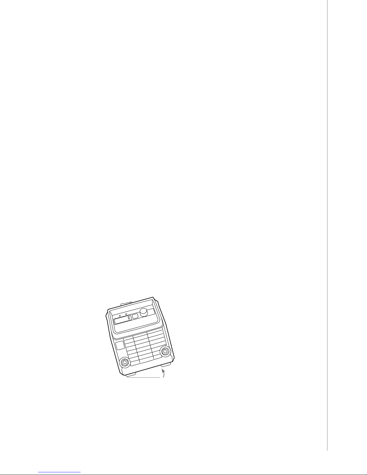
3.2.1 Power source.................................................................................................................... 6
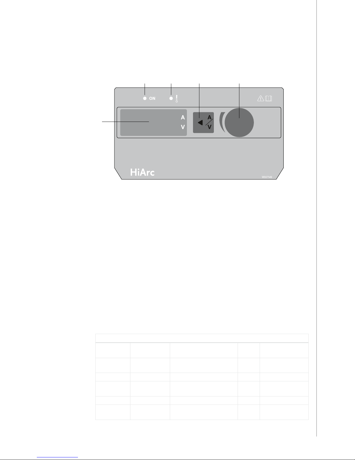
3.2.2 Control panel and SETUP functions, HiArc S 400R ........................................................ 7
3.2.3 Activation and setup parameter adjustment, HiArc S 400R ......................................... 7
3.2.4 Control panel and SETUP functions, HiArc S 400A........................................................ 8
3.2.5 Activation and setup parameter adjustment, HiArc S 400A......................................... 9
3.3 MMA welding.........................................................................................................................10
3.3.1 Filler materials and equipment.....................................................................................10
3.3.2 Earth return cable and clamp .......................................................................................10
3.3.3 Manual metal arc welding (MMA) ................................................................................10
3.3.4 Electrode welding parameter table..............................................................................11
3.3.5 Arc force, HiArc S 400A..................................................................................................11
3.3.6 Hot start, HiArc S 400A ..................................................................................................11
3.4 TIG welding.............................................................................................................................12
3.5 Carbon arc gouging.............................................................................................................13
4. Maintenance......................................................................................................................13
4.1 Regular maintenance..........................................................................................................13
4.1.1 Every six months............................................................................................................13
4.2 Service contract ....................................................................................................................13
4.3 Storage .....................................................................................................................................13
4.4 Disposal of the machine ....................................................................................................14
5. Troubleshooting..............................................................................................................14
5.1 Troubleshooting ...................................................................................................................14
5.2 Control panel error codes .................................................................................................15
6. Ordering codes.................................................................................................................15
7. Technical data...................................................................................................................16

3
© Kemppi Oy / 1418
EN
1. INTRODUCTION
1.1 General
Congratulations on choosing the HiArc series power source. Used correctly, Kemppi products
can signicantly increase the productivity of your welding, and provide years of economical
service.
This operating manual contains important information on the use, maintenance and safety of
your Kemppi product. The technical specications of the device can be found at the end of the
manual.
Please read the operating manual and the safety instructions booklet carefully before using
the equipment for the rst time. For your own safety and that of your working environment,
pay particular attention to the safety instructions.
For more information on Kemppi products, contact Kemppi Oy, consult an authorised Kemppi
dealer, or visit the Kemppi web site at www.kemppi.com.
The specications presented in this manual are subject to change without prior notice.
Important notes
Items in the manual that require particular attention in order to minimise damage and
personal harm are indicated with the ’NOTE!’ notation. Read these sections carefully and follow
their instructions.
Disclaimer
While every eort has been made to ensure that the information contained in this guide
is accurate and complete, no liability can be accepted for any errors or omissions. Kemppi
reserves the right to change the specication of the product described at any time without
prior notice. Do not copy, record, reproduce or transmit the contents of this guide without
prior permission from Kemppi.
1.2 Product introduction
HiArc S model welding machines are designed for industrial use and for welding all kinds of
covered electrodes.
Model 400R includes a regular control panel with the basic functions. Model 400A has also
advanced functions like HotStart, ArcForce, TIG mode and remote control.
HiArc S 400A comes equipped with a voltage reduction device (VRD) for maintaining the
open-circuit voltage (OCV) below 35 volts.

HiArc S 400R, 400A
4
EN
1.3 Machine introduction
HiArc S 400R
1.
3.
6.
4.
2.
5.
7.
8.
9.
1. Power on pilot lamp
2. Overheating pilot lamp
3. Amperage/voltage meter display
4. Amperage/voltage meter display selection button
5. Welding current adjustment knob
6. Negative (-) pole connection socket (earth return cable)
7. Positive (+) pole connection socket (welding cable)
8. Main switch (ON/OFF)
9. Mains power cable
HiArc S 400A
1.
3.
5. 7.
10.
4.
6.
14.
8.
2.
9.
11.
12.
13.
1. Power on pilot lamp
2. Overheating pilot lamp
3. Amperage/voltage meter display
4. Amperage/voltage meter display selection button
5. ArcForce
6. HotStart

5
© Kemppi Oy / 1418
EN
7. Remote Control
8. Welding Mode
9. Welding current adjustment knob
10. Negative (-) pole connection socket (earth return cable)
11. Positive (+) pole connection socket (welding cable)
12. Main switch (ON/OFF)
13. Mains power cable
14. Remote control connector
There is an optional display cover available to protect the panel form sparks, dust and
scratches. See 'Ordering codes'.
2. INSTALLATION
2.1 Before use
The product is packed in cartons designed specically for them. However, always make sure
before use that the products have not been damaged during transportation.
Check also that you have received the components you ordered and the instruction manuals
needed. Product packaging material is recyclable.
NOTE! When moving the welding machine, always lift it from the handle, never pull it from the
welding or other cables.
Operating environment
This machine is suitable for both indoor and outdoor use. Always make sure that the air ow in
the machine is unrestricted. The recommended operating temperature range is –20…+50 °C.
Please read also the Safety Instructions concerning the operating environment.
2.2 Positioning of the machine
Place the machine on a sturdy, level surface that is dry and does not allow dust or other
impurities to enter the machines cooling air ow. Preferably site the machine to a suitable
carriage unit so it is above oor level.
Notes for positioning the machine
• The surface inclination may not exceed 15 degrees.
< 15°
• Ensure the free circulation of the cooling air. There must be at least 20 cm of free space in
front of and behind the machine for cooling air circulation.
• Protect the machine against heavy rain and direct sunshine.
The machine is not allowed to be operated in the rain as the protection class of the machine,
IP23S, allows preserving and storing outside only.
NOTE! Never aim the spray of sparks from a grinding machine toward the equipment.

HiArc S 400R, 400A
6
EN
2.3 Distribution network
All regular electrical devices without special circuits generate harmonic currents into
distribution network. High rates of harmonic current may cause losses and disturbance to
some equipment.
2.4 Welding and earth return cable connections
2.4.1 Choosing welding polarity in MMA welding
You can change the welding polarity by choosing (+) or (–) cable connector. Typically, in MMA
welding, the welding cable is connected to the positive (+) pole connection socket and the
earth return cable to the negative (-) pole connection socket.
2.4.2 Choosing welding polarity in TIG welding
In TIG welding the welding cable must be connected to the negative (-) pole connection
socket and the earth return cable to the positive (+) pole connection socket.
2.4.3 Earthing
If possible, always fasten the clamp of the earth return cable directly onto work piece.
1. Clean contact surface of the clamp from paint and rust.
2. Fasten the clamp properly, so that contact surface is as large as possible.
3. Check that the clamp is fastened rmly.
3. OPERATION
NOTE! Welding in places presenting an immediate re or explosion hazard is forbidden! Welding fumes
may cause injury, take care of sucient ventilation during welding!
3.1 Welding processes
3.1.1 MMA welding
MMA welding, as well as carbon arc gouging, is possible with all HiArc S power sources.
A separate HiArc S 400A model including cellulose kit is also available. See 'Ordering codes'.
3.1.2 TIG
For TIG welding with the A model a separate TIG-torch with gas valve is required. See 'Ordering
codes'.
NOTE! TIG welding is not possible with R model.
3.2 Operation functions
3.2.1 Power source
NOTE! Always switch the machine on and o from main switch. Do not use the mains plug for
switching!
NOTE! Never watch the arc without a proper face shield designed for arc welding! Protect yourself
and the surroundings against welding arc and hot spatters!

7
© Kemppi Oy / 1418
EN
3.2.2 Control panel and SETUP functions, HiArc S 400R
WeldData
After welding has nished, the display shows the measured average current of the last weld.
This weld data is only displayed if the welding cycle lasts for 5 seconds or more.
Regular control panel
1.
5.
2. 3. 4.
1. The green ON light indicates that the power source is turned on.
2. Overheating indicator. Light indicates that the machine is overheated.
3. Amperage/voltage meter display selection button.
• Short press to select either amperage or voltage values to the display. Values can be
adjusted during welding.
• Long press (> 5 s) activates setup function.
4. Welding current adjustment knob. Turn the knob to set the welding current value.
5. Amperage/voltage meter display. Shows used current/voltage values during welding
and the set current value when not welding.
3.2.3 Activation and setup parameter adjustment, HiArc S 400R
1. Press A/V selection button (3) for at least 3 seconds, until the text ”Set” appears on the
screen.
2. Choose the needed parameter with the welding current adjustment knob (4).
3. To select the required parameter, press the A/V selection button (3). You can move from
adjustment mode to selection mode with a new press of button (3).
4. Use the Welding current adjustment knob (4) to adjust the parameter value.
5. You can exit Setup mode with a long press of A/V selection button (3). Setup parameters
are saved when you exit Setup.
Setup menu structure
Regular control panel
Name Function Description Factory
default
Adjustment range
Elt. Electrode type Selection of electrode type between
basic and rutile electrodes
Rut bAS/RUt
Hot. HotStart selection ON ON/OFF
Cab. Long cables Long cable mode for welding circuits
of 50 m and longer (max. 80 m).
OFF ON/OFF
GEn Generator Generator mode OFF ON/OFF
Fac. Restore factory
settings
OFF rES/OFF

HiArc S 400R, 400A
8
EN
3.2.4 Control panel and SETUP functions, HiArc S 400A
WeldData
After welding has nished, the display shows the measured average current of the last weld.
This weld data is only displayed if the welding cycle lasts for 5 seconds or more.
Advanced control panel
1.
7.
6.
2. 3.
8.
4.
9.
5.
10.
1. The green ON light indicates that the power source is turned on.
2. Overheating indicator. Light indicates that the machine is overheated.
3. VRD indicator. Light indicates that VRD is set on.
• Solid green light: VRD is set ON and OCV is under 35V.
• Blinking red light: VRD is set ON and OCV is over 35 V.
4. Amperage/voltage meter display selection button.
• Short press to select either amperage or voltage values to the display. Values can be
adjusted during welding.
• Long press (> 5 s) activates setup function.
5. Welding current adjustment knob. Turn the knob to set the welding current value.
6. Amperage/voltage meter display. Shows used current/voltage values during welding
and the set current value when not welding.
7. ArcForce. The smaller the value, the softer the arc. When using a bigger value, the harder
the arc gets. Factory setting in the middle.
8. HotStart. Factory setting in the middle. Adjust to value 0 = no HotStart, adjust to 10 =
HotStartMax
9. Welding Mode. Press to select TIG or MMA mode. Light indicates the selection.
10. Remote Control. Press to select remote or panel control. Light indicates remote control.

9
© Kemppi Oy / 1418
EN
3.2.5 Activation and setup parameter adjustment, HiArc S 400A
1. Press A/V selection button (3) for at least 3 seconds, until the text ”Set” appears on the
screen.
2. Choose the needed parameter with the welding current adjustment knob (4).
3. To select the required parameter, press the A/V selection button (3). You can move from
adjustment mode to selection mode with a new press of button (3).
4. Use the Welding current adjustment knob (4) to adjust the parameter value.
5. You can exit Setup mode with a long press of A/V selection button (3). Setup parameters
are saved when you exit Setup.
Setup menu structure
Advanced control panel
Name Function Description Factory
default
Adjustment
range
Cel. Cellulosic Cellulosic option selection. This selection must
be On, if Cel kit is assembled.
On
(device specic)
On/OFF
Ant. Antifreeze If Antifreeze selection is On, the machine cuts o
the power and protects the electrode if sticking
occurs during the welding
On On/OFF
Cab. Long cables Long cable mode for welding circuits of 50 m
and longer (max. 80 m)
OFF On/OFF
Gen. Generator Generator mode for generator use and
uctuating mains networks
OFF On/OFF
rcL Remote Low Current limit Limits the remote adjustment range. Allows
more exact remote adjustment.
30 30–MAX
rcH Remote High Current limit Limits the remote adjustment range. Allows
more exact remote adjustment.
MAX 30–MAX
Urd VRD selection Reduces open circuit voltage below 35V OFF
(device specic)
On/OFF
Fac. Restore Factory Settings Restores setup and panel settings to factory
default
OFF rES/OFF
Voltage Reduction Device (VRD)
HiArc S 400A contains a voltage reduction device (VRD), which reduces the open-circuit
voltage below 35 V. This reduces the risk of electric shock in particularly dangerous
environments, such as closed or damp spaces. VRD is activated through the setup menu.
VRD is a feature of HiArc S 400A model, not available on the R model.

HiArc S 400R, 400A
10
EN
3.3 MMA welding
In manual metal arc welding (MMA), the ller material is melted from the electrode to the
weld pool. The rate of welding current is selected on the basis of the electrode size and
welding position. The arc forms between the electrode tip and work piece. The melting
electrode coating forms a gas and slag shield, which protects the molten metal in transfer
to the weld pool and during solidication. As the slag solidies over the hot weld metal, it
prevents weld metal from oxidation. This slag coating is removed after welding e.g. with a
chipping hammer. When removing the slag coating, ensure you protect your eyes and face
with suitable equipment.
For more info, visit www.kemppi.com > Welding ABC.
3.3.1 Filler materials and equipment
HiArc S series can be used with most of the common electrode types for DC welding. For
welding with cellulosic electrodes, the optional kit should be tted. Electrode sizes for the unit
are listed in Technical data section later in this manual. Follow the welding specications given
on the electrode package.
1. Check that the welding cable and earth return cable connections are hand tight.
If a cable connection is loose, it will result in a decrease of welding performance,
overheating of the connection, and it may aect your product warranty cover.
2. Select and mount the correct electrode type rmly in holder.
3.3.2 Earth return cable and clamp
If possible, always x the earth return cable and clamp directly to the welding work piece.
1. Clean the connection surface of the clamp from paint, dirt and rust.
2. Connect the clamp carefully so that contact surface is as large as possible.
3. Finally check that the clamp remains fastened.
3.3.3 Manual metal arc welding (MMA)
Select your required welding parameters according to the manufacturer’s ller material
recommendations and the joint to be welded.
1. Select the required polarity (+ or –) of welding current cable (normally + ) and
earth return cable (normally –) according to the ller material manufacturers
recommendations.
2. Depending on the HiArc S series model, select MMA welding mode by pressing the
process selection button on the control panel.

11
© Kemppi Oy / 1418
EN
3. Select a suitable welding current by adjusting the current adjustment knob.
4. Make a small test weld to check the selections made.
Site your equipment in a suitable location, ensuring there is adequate cable length to
complete the weld pass. Before you start welding, ensure you are comfortably positioned in
front of the work piece, and that you are well balanced with your weight equally distributed.
Ensure that the power source current setting is correct for the electrode size selected. Draw
the welding face shield over your eyes. (Electronic welding face shields like Kemppi Beta
90X allow you to see the welding start point more accurately and better concentrate on the
welding process. This reduces the possibility of arc ash).
NOTE! Ensure others in the welding area are aware that you're going to weld.
To establish the arc, scratch the electrode on the surface of the work piece.
As the arc starts, move the welding electrode at a pulling angle. The boundary of the slag
formed is visible after the molten weld. It must be behind the molten weld. The distance of
the slag boundary from the molten weld can be adjusted with the welding current and the
angle of the electrode. Throughout the welding, concentrate on the length of the arc and
keep it as short as possible. The length of the arc increases easily as the electrode decreases in
length during the welding. End welding by moving the welding electrode slightly back to the
completed weld and then lifting the electrode straight away from the work piece.
Your completed weld bead should be straight and of even width and bead height, consistent
in its appearance. Travel too slowly during welding and the weld pool will get too big and may
burn through the weld piece, too fast and the resulting weld will be too small and may have
slag entrapments and/or poor strength. After welding, the solidied slag on the weld surface
should easily remove with a chipping hammer. Ensure you wear eye and face protection when
removing the slag from the weld surface.
3.3.4 Electrode welding parameter table
Electrode diameter (mm) Rutile E6013 (A) Basic E7018 (A)
1.6 30–60 30–55
2.0 50–70 50–80
2.5 60–100 80–110
3.25 80–150 90–140
4.0 100–200 125–210
5.0 150–290 200–260
6.0 200–385 220–340
7.0 280–410
3.3.5 Arc force, HiArc S 400A
Adjusting arc force by turning the ArcForce knob will aect the roughness of the arc. Factory
setting for all electrode types is in the middle. When the knob is turned counter-clockwise the
arc is softened and the amount of spatter decreases when welding at the upper end of the
recommended current range of the electrode. When the knob is turned clockwise the arc gets
rougher.
3.3.6 Hot start, HiArc S 400A
HotStart increases the current for the arc ignition momentarily. With very thin work pieces hot
start is generally not needed (depends on the electrode type).
The hot start value is selected between 0 and 10. Zero shuts HotStart o (no HotStart) and 10
sets it to HotStartMax. Factory setting is 5.

HiArc S 400R, 400A
12
EN
3.4 TIG welding
TIG welding is possible only with HiArc S 400A model, not with the R model.
NOTE! In TIG welding the welding cable must be connected to the negative (-) pole connection
socket and the earth return cable to the positive (+) pole connection socket.
Select your required welding parameters according to the manufacturer’s ller material
recommendations and the joint to be welded.
1. Select the required polarity of welding current cable (-) and earth return cable (+) for TIG
welding.
2. Select TIG welding mode by pressing the process selection button on the control panel.
3. Select a suitable welding current by adjusting the current adjustment knob.
4. Make a small test weld to check the selections made.
Shielding gas is used in DC TIG welding. Your dealer will give you advice on choosing gas and
equipment.
You can start welding after having made the necessary selections. Open the gas valve on the
TTM 15 V BC. When gas starts to ow, arc is lit by lightly scratching work piece with the tip of
the tungsten electrode, or with the touch and lift method (see 'Ignition by Lift TIG'). When arc
is lit, its length is regulated by holding the tip of the tungsten electrode at a suitable distance
from the work piece. Suitable arc length is usually about half the diameter of the electrode
core wire. Move the torch forwards from the starting point. If necessary, adjust current value.
The ller material, tungsten electrode and the welding current level are decided according to
the base material type and thickness, joint form and welding position.
Stop welding by lifting the torch o the welding piece and by closing the gas valve on the
torch.
NOTE! The torch voltage will remain on.
NOTE! Always x the gas cylinder so that it stays steadily in upright position either in specially
made wall rack or cylinder trolley. Always close the cylinder valve after having nished welding.
Ignition by Lift TIG
You can ignite TIG arc with the Lift TIG method. Gently touch the work piece with the
electrode and quickly lift the electrode from the work piece to a suitable welding distance to
ignite the arc. If electrode contact with the work piece exceeds 1 second, the power source
ignition will automatically shut o preventing damage to the electrode.
To stop welding, quickly pull the electrode away from the work piece.
< 1.0 s
Order information for the additional equipment (TIG torch) required for TIG welding can be
found in 'Ordering codes' section later in this manual.

13
© Kemppi Oy / 1418
EN
3.5 Carbon arc gouging
Refer to the table below for amperage settings for carbon arc gouging.
Electrode Amperage (A)
6.35 mm (1/4”) 170–330 A
8 mm (5/16”) 230–450 A
4. MAINTENANCE
NOTE! Watch out for mains voltage when handling electric cables!
Degree and circumstances of machine utilisation should be taken into consideration when
planning product maintenance. Careful use and preventive maintenance helps to avoid
unnecessary production disturbances and breaks. Check the condition of the welding and
connection cables daily. Do not use damaged cables.
4.1 Regular maintenance
4.1.1 Every six months
NOTE! Disconnect the plug of the machine from the mains socket and wait for about 2 minutes
before removing the casing plate.
The following maintenance operations should be carried out at least every six months:
• Electric connections of the machine – clean any oxidised parts and tighten any loose
ones.
NOTE! You must know the correct tension torques before you start repairing the connections.
• Clean the inner parts of the machine from dust and dirt e.g. with a soft brush and a
vacuum cleaner. Do not use compressed air because there is the danger that the dirt
is packed even more tightly in the gaps of the cooling proles. Do not use a pressure
washer.
NOTE! Only an authorised electrician may repair the machine.
NOTE! The machine and control panel are at mains current potential. DO NOT remove either the
cover or control panel unless authorised to do so. Only authorised and trained personnel can carry
out maintenance and repair processes.
4.2 Service contract
Kemppi service workshops make special service contracts with customers about regular
maintenance. All parts are cleaned, checked and if necessary, repaired. Also the operation of
welding machine is tested.
4.3 Storage
The machine must be stored in a clean and dry room. Protect the machine from rain and direct
sunshine in places where temperature exceeds +25 °C.

HiArc S 400R, 400A
14
EN
4.4 Disposal of the machine
Do not dispose of electrical equipment with normal waste!
Electrical equipment that has reached the end of its life must be collected separately and
taken to an appropriate environmentally responsible recycling facility.
The owner of the equipment is obliged to deliver a decommissioned unit to a regional
collection centre, as per the instructions of local authorities or a Kemppi representative. By
applying this you will improve the environment and human health.
5. TROUBLESHOOTING
The control panel will display any errors of the system. Error code numbers are shown in the
display and can be compared to the table below.
5.1 Troubleshooting
Power On light is not illuminated.
There is no electrical power to the machine.
• Check the mains electrical supply is connected.
• Check the mains fuses, replace blown fuses.
• Check the mains cable and plug, replace defect parts.
The machine is not welding properly. Welding creates spatter. The weld joint is porous or
power supply is insucient.
• Check the welding parameter settings and adjust if needed. See welding parameter
table on page 9.
• Check that the earth return clamp is properly fastened and that earth return cable has no
defects. If necessary change the clamp location and replace defective parts.
• Check the welding cable and connector. Tighten the connection(s) and replace defective
parts.
Power source overheating pilot lamp is illuminated.
Power source has exceeded the designed working temperature. Fans are running and the
machine is in a cooling down cycle. The machine will reset automatically.
• Check that there is enough free space around the machine for cooling air circulation.
• In some cases when error occurs, the machine turns o. Then user must turn the main
switch o and on again.
• Check that welding circuit is open.

15
© Kemppi Oy / 1418
EN
5.2 Control panel error codes
Error 1 (E1) Power source is not calibrated. Calibrate power source.
Error 2 (E2) Undervoltage Check the mains network connection and fuses.
Error 3 (E3) Overvoltage Check the mains network connection and fuses.
Error 4 (E4) Overheating. Also the overheating pilot lamp
is on. Machine drops welding current for 30s. If
error conditions still apply:
Machine stops welding (model A)
Machine shuts down (model R).
Ensure free air ow. Let the machine cool down.
Error 5 (E5) ---
Error 6 (E6) ---
Error 7 (E7) NTC warning. (IGBT overheating). Machine
drops welding current.
Ensure free air ow. Let the machine cool down. Check
the environment temperature.
Error 8 (E8) NTC error. (IGBT overheating). If error
conditions (Err7) still apply:
Machine stops welding (model A)
Machine shuts down (model R).
Ensure free air ow. Let the machine cool down. Check
the environment temperature.
Error 9 (E9) Mains network phase alarm. Check the mains network connection and fuses. If
connected to generator check setup jumper Gen.
Error 10 (E10) ---
Error 11 (E11) VRD error.
Error 12 (E12) Power source is locked. Too long short circuit.
Machine stops welding (model A)
Machine shuts down (model R).
Avoid long short circuits (20s).
Error 13 (E13) Wrong panel type (R-type control panel
connected to A-type HiArc or vice versa).
R-type HiArc accepts only R-type (regular) control
panel.
Error 14 (E14) Current feedback is missing. Contact Kemppi service representative.
6. ORDERING CODES
HiArc S 400R 63114002
HiArc S 400A 63114001
HiArc S 400A cellulose kit included 6311400101
Welding cable 50 mm², 5 m 6184501H
70 mm², 5 m 6184701H
Earth return cable 50 mm², 5 m 6184511H
70 mm², 5 m 6184711H
Display cover SP006989
Slide bars SP007023
R10H remote control for HiArc S 400A 6185431H
TTM 15 V BC 4 m 627143201

HiArc S 400R, 400A
16
EN
7. TECHNICAL DATA
HiArc S 400R HiArc S 400A
Connection voltage 3~50/60 Hz 380 – 440V (-10…+10 %) 380 – 440V (-10 %…+10 %)
Rated power at max. current 60 % ED 20 kVA 20kVA
Fuse (delayed) 25 A 25 A
Output at 40 °C MMA 60 % ED 400 A / 36V 400 A / 36V
MMA 100 % ED 310 A / 32.4 V 310 A / 32.4V
TIG 60 % ED - 400 A / 26V
TIG 100 % ED - 310 A / 22.4V
Welding voltage (max) 400 A / 48V 400 A / 48V
Electrodes, ø1.6...7.0 mm 1.6...7.0 mm
Welding current control stepless stepless
Power factor at 100 % 0.90 0.90
Operating temperature range -20…+50 °C -20…+50 °C
Efficiency at 100 % 0.89 0.89
Degree of protection IP23S IP23S
EMC class A A
External dimensions L xW x H 570 x 270 x 340 mm 570 x 270 x 340 mm
Weight 19.5 kg 20 kg


www.kemppi.com
1921800
1418
KEMPPI OY
Kempinkatu 1
PL 13
FIN-15801 LAHTI
FINLAND
Tel +358 3 899 11
Telefax +358 3 899 428
www.kemppi.com
Kotimaan myynti:
Tel +358 3 899 11
Telefax +358 3 734 8398
myynti.@kemppi.com
KEMPPI SVERIGE AB
Box 717
S-194 27 UPPLANDS VÄSBY
SVERIGE
Tel +46 8 590 783 00
Telefax +46 8 590 823 94
sales.se@kemppi.com
KEMPPI NORGE A/S
Postboks 2151, Postterminalen
N-3103TØNSBERG
NORGE
Tel +47 33 346000
Telefax +47 33 346010
sales.no@kemppi.com
KEMPPI DANMARK A/S
Literbuen 11
DK-2740 SKOVLUNDE
DANMARK
Tel +45 4494 1677
Telefax +45 4494 1536
sales.dk@kemppi.com
KEMPPI BENELUX B.V.
NL-4801 EA BREDA
NEDERLAND
Tel +31 765717750
Telefax +31 765716345
sales.nl@kemppi.com
KEMPPI (UK) LTD
Martti Kemppi Building
Fraser Road
Priory Business Park
BEDFORD, MK44 3WH
UNITED KINGDOM
Tel +44 (0)845 6444201
Telefax +44 (0)845 6444202
sales.uk@kemppi.com
KEMPPI FRANCE S.A.S.
65 Avenue de la Couronne des Prés
78681 EPONE CEDEX
FRANCE
Tel +33 1 30 90 04 40
Telefax +33 1 30 90 04 45
sales.fr@kemppi.com
KEMPPI GMBH
Perchstetten 10
D-35428 LANGGÖNS
DEUTSCHLAND
Tel +49 6 403 7792 0
Telefax +49 6 403 779 79 74
sales.de@kemppi.com
KEMPPI SPÓŁKA Z O.O.
Ul. Borzymowska 32
03-565WARSZAWA
POLAND
Tel +48 22 7816162
Telefax +48 22 7816505
KEMPPI AUSTRALIA PTY LTD
13 Cullen Place
P.O. Box 5256, Greystanes NSW 2145
SMITHFIELD NSW 2164
AUSTRALIA
Tel. +61 2 9605 9500
Telefax +61 2 9605 5999
OOO KEMPPI
Polkovaya str. 1, Building 6
127018 MOSCOW
RUSSIA
Tel +7 495 240 84 03
Telefax +7 495 240 84 07
ООО КЕМППИ
ул. Полковая 1, строение 6
127018 Москва
Tel +7 495 240 84 03
Telefax +7 495 240 84 07
KEMPPI, TRADING (BEIJING) COMPANY LTD
Room 420, 3 Zone, Building B,
No.12 Hongda North Street,
Beijing Economic Development Zone,
100176 BEIJING
CHINA
Tel +86-10-6787 6064
+86-10-6787 1282
Telefax +86-10-6787 5259
sales.cn@kemppi.com
肯倍贸易(北京)有限公司
中国北京经济技术开发区宏达北
路12号
创新大厦B座三区420室 (100176)
电话: +86-10-6787 6064
+86-10-6787 1282
传真: +86-10-6787 5259
sales.cn@kemppi.com
KEMPPI INDIA PVT LTD
LAKSHMITOWERS
New No. 2/770,
First Main Road,
Kazura Garden,
Neelankarai,
CHENNAI - 600 041
TAMIL NADU
Tel +91-44-4567 1200
Telefax +91-44-4567 1234
sales.india@kemppi.com
KEMPPI WELDING SOLUTIONS SDN BHD
No 12A, JalanTP5A,
Taman Perindustrian UEP,
47600 Subang Jaya,
SELANGOR, MALAYSIA
Tel +60 3 80207035
Telefax +60 3 80207835
sales.malaysia@kemppi.com
This manual suits for next models
1
Table of contents
Popular Portable Generator manuals by other brands

Powermate
Powermate PC0496504.18 user manual

Firman
Firman H03651 owner's manual

VICI DBS
VICI DBS NM PLUS user manual

Pacific Scientific
Pacific Scientific Redi-Line DA12A Installation and service manual

Peak
Peak Genius XE SMZ user manual

Generac Power Systems
Generac Power Systems PowerBOSS Contractor 1648-0 owner's manual

SDMO
SDMO R 340 U User and maintenance manual

EXTOL Craft
EXTOL Craft 421000 user manual

Kohler
Kohler 1.4BEOR-12V Operation

Thunder Scientific
Thunder Scientific 2500 series Operation and maintenance manual

Lincoln Electric
Lincoln Electric Idealarc DC-1500 Service manual

Rentquip
Rentquip Patron GI-2000 Operation manual