KRC-356D/L/N
CONTENTS
/
CONNECTIONS
CONTENTS
PC
BOARD
(COMPONENT
SIDE
VIEW)
................
23
CONNECTIONS
os
sicssssovssessncccontdaceocctassstvacecsiieecesteies
2
PC
BOARD
(FOIL
SIDE
VIEW)
..............eeeeeeeeeeees
BLOCK
DIAGRAM
uuu...
ioc
ecceccseceseneeeeteeeneetereeatenee
3
SCHEMATIC
DIAGRAN
......00.....ce
cc
ceeeeeeeeereeeteene
CIRCUIT
DESCRIPTION
.....0.0..
oe.
cece
eeeeseeteeeeee
il
EXPLODED
VIEW
(MECHANISM)
DISASSEMBLY
FOR
REPAIR
(MECHANIS®)
.......
10
EXPLODED
VIEW
(UINIT)
......
ccc
cceeceesseetrseenees
MECHANISM
OPERATION
DESCRIPTION
...........
11
PARTS
LIST
ociicscccasisienicicinnteesesseeuiisiade
casted
ADJUSTMENT
..........ccecccccsessscssssseecsseeeceeseeeeeneeens
20
SPECIFICATIONS
o.oo.
eee
eeeee
eens
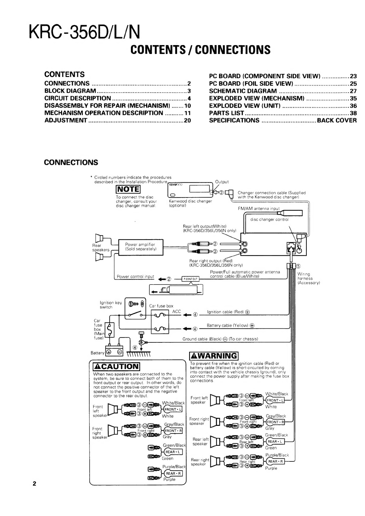
CONNECTIONS
*
Circled
numbers
indicate
the
procedures
described
in
the
Installation
Procedure
To
connect
the
disc
changer,
consult
your
disc
changer
manual!
(optional)
Rear
left
outout(White)
(KRC-356D/356L/356N
oniy)
Power
amplifier
(Soid
separately)
Rear
speakers
Power
control
input
-®
Ignition
key
switch
Battery
@
©
ACAUTION
When
two
speakers
are
connected
to
the
system,
be
sure
to
connect
both
of
them
to
the
front
output
or
rear
output.
In
other
words,
do
not
connect
the
positive
connector
of
the
left
speaker
to
the
front
output
and
the
negative
connector
to
the
rear
output.
Hes
@O@
ayes.
White/Black
Front
left
White
Gray/Black
Sra,
Kenwood
disc
change’
—-
©®
<—_©®
Output
Changer
connection
cable
(Supplied
with
the
Kenwood
disc
changer)
FM/AM
antenna
input
disc
changer
control
Rear
right
output
(Red)
(KRC-356D/356L/356N
only)
[H1é
Power/Full
a
nah
power
antenna
Wiring
contro!
cable
(Blue/White)
[
P.cont
ouT
}
harness
(Accessory)
Ignition
cable
(Red)
@
Battery
cable
(Yellow)
®
Ground
cable
(Black)
©
{To
car
chassis)
To
prevent
fire
when
the
ignition
cable
(Red)
or
battery
cable
(Yellow)
is
short-circuited
by
coming
into
contact
with
the
vehicle
chassis
(ground),
only
connect
the
power
supply
after
making
the
fuse
box
connections
sees
White/Black
Front
left
®
7
speaker
ront
left
SORE
White
-
seams,
Gray/Black
Front
right
Sols
y
speaker
O@Ee
~
Suen
Green/Black
Rear
left
20s
sa
(FERAL
]
speaker
@
Owen
os
lack
.
OCS
Purple/B
Rear
right
Rear
right
speaker
OLO)i=--
=
-
purple