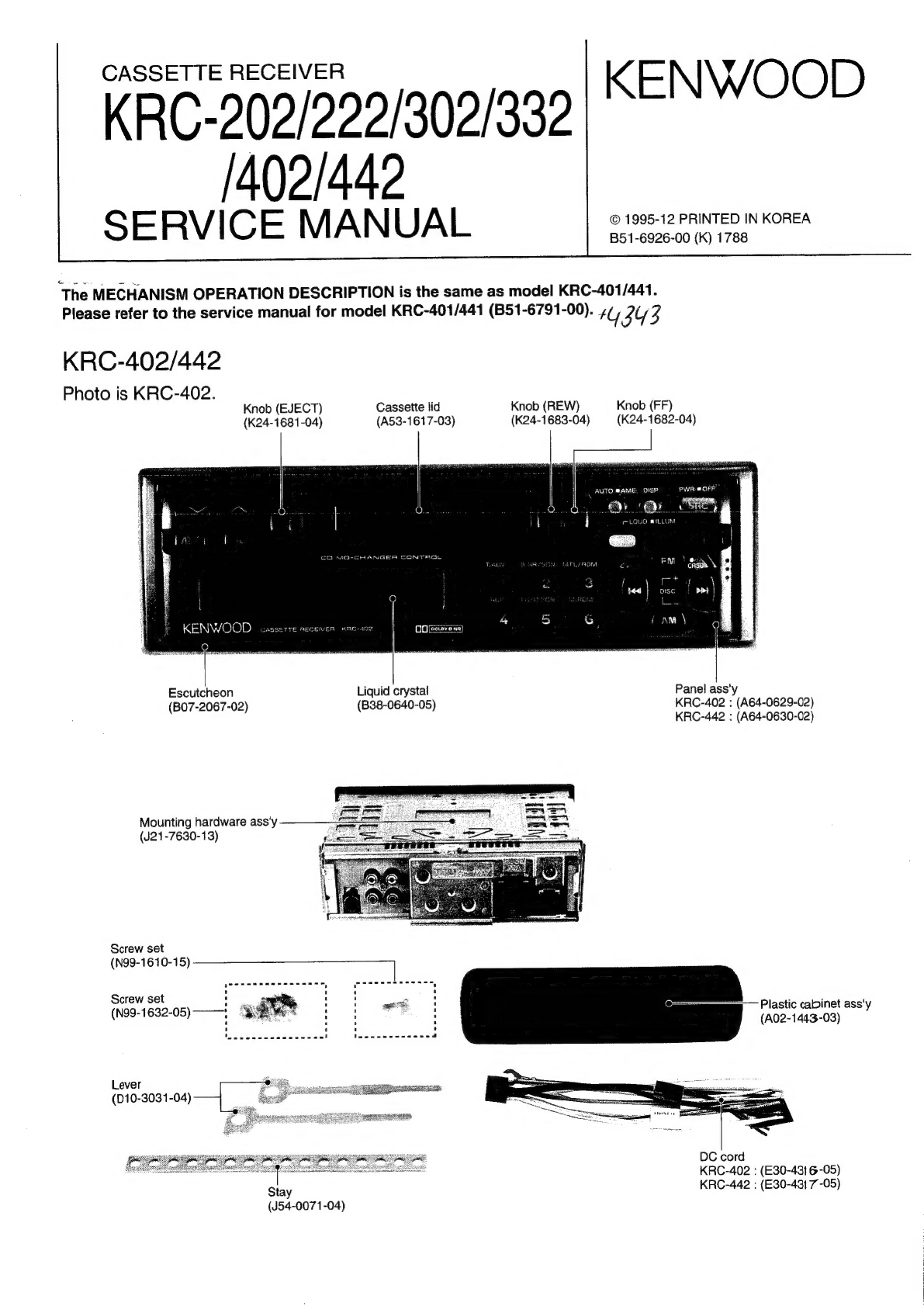
Kenwood KRC-402 User manual
Other Kenwood Car Receiver manuals

Kenwood
Kenwood KDC-6011 User manual

Kenwood
Kenwood KDC-PS9070R User manual

Kenwood
Kenwood KRC-578R User manual

Kenwood
Kenwood KDC-PS900 User manual

Kenwood
Kenwood KDC-X679 User manual

Kenwood
Kenwood KRC-12 User manual

Kenwood
Kenwood KDC-7090R User manual

Kenwood
Kenwood KDC-X617 User manual

Kenwood
Kenwood DDX7015 - Excelon - DVD Player User manual

Kenwood
Kenwood KDV-MP6032U User manual

Kenwood
Kenwood DP-M6650 User manual

Kenwood
Kenwood KRC-2100 User manual

Kenwood
Kenwood KRC-291 User manual

Kenwood
Kenwood KRC-709 User manual

Kenwood
Kenwood KDC-V7017 User manual

Kenwood
Kenwood KRC-2904A User manual

Kenwood
Kenwood KDC-MP443 User manual

Kenwood
Kenwood KDC-X915 User manual

Kenwood
Kenwood KDC-348U User manual

Kenwood
Kenwood KMM-BT304 User manual