manuals.online logo
Brands
  1. Home
  2. •
  3. Brands
  4. •
  5. Kenwood
  6. •
  7. CD Player
  8. •
  9. Kenwood DP-4020 User manual

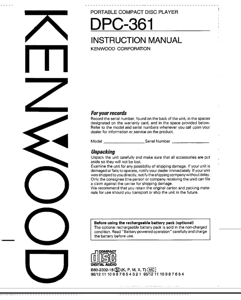
Kenwood DP-4020 User manual

Other manuals for DP-4020

2

Other Kenwood CD Player manuals

Kenwood DVF-S500 User manual

Kenwood

Kenwood DVF-S500 User manual

Kenwood DP-R893 User manual

Kenwood

Kenwood DP-R893 User manual

Kenwood KDC-C461 User manual

Kenwood

Kenwood KDC-C461 User manual

Kenwood KDC-V6017 User manual

Kenwood

Kenwood KDC-V6017 User manual

Kenwood DPC-731 User manual

Kenwood

Kenwood DPC-731 User manual

Kenwood DPC-761 User manual

Kenwood

Kenwood DPC-761 User manual

Kenwood L-1000D User manual

Kenwood

Kenwood L-1000D User manual

Kenwood DPC-55 User manual

Kenwood

Kenwood DPC-55 User manual

Kenwood DP-M5550 User manual

Kenwood

Kenwood DP-M5550 User manual

Kenwood DP-7010 User manual

Kenwood

Kenwood DP-7010 User manual

Kenwood DVF-N7080 User manual

Kenwood

Kenwood DVF-N7080 User manual

Kenwood DP-M107R User manual

Kenwood

Kenwood DP-M107R User manual

Kenwood DP-R6070 User manual

Kenwood

Kenwood DP-R6070 User manual

Kenwood DPC-341 User manual

Kenwood

Kenwood DPC-341 User manual

Kenwood KDV-C810 User manual

Kenwood

Kenwood KDV-C810 User manual

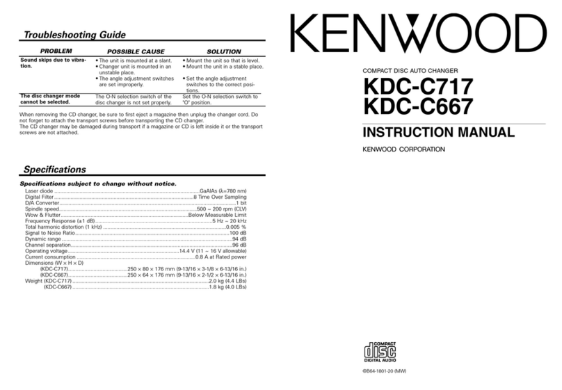
Kenwood KDC-C667 User manual

Kenwood

Kenwood KDC-C667 User manual

Kenwood CD-223M User manual

Kenwood

Kenwood CD-223M User manual

Kenwood DVF-3500 User manual

Kenwood

Kenwood DVF-3500 User manual

Kenwood DP-R6080 User manual

Kenwood

Kenwood DP-R6080 User manual

Kenwood DPC-951 User manual

Kenwood

Kenwood DPC-951 User manual

Kenwood CD-425M User manual

Kenwood

Kenwood CD-425M User manual

Kenwood DP-1060 User manual

Kenwood

Kenwood DP-1060 User manual

Kenwood CD-2260M User manual

Kenwood

Kenwood CD-2260M User manual

Kenwood DPC-X337 User manual

Kenwood

Kenwood DPC-X337 User manual

Popular CD Player manuals by other brands

Arcam CD23 Handbook

Arcam

Arcam CD23 Handbook

Sanyo MCD-Z1F Service manual

Sanyo

Sanyo MCD-Z1F Service manual

JVC RC-ST3SL instructions

JVC

JVC RC-ST3SL instructions

Technics SL-P9066 operating instructions

Technics

Technics SL-P9066 operating instructions

Marantz HD-CD1 quick start guide

Marantz

Marantz HD-CD1 quick start guide

Sony DVP-FX850 Service manual

Sony

Sony DVP-FX850 Service manual

Philips AZ1140 Instrukcja obs?ugi

Philips

Philips AZ1140 Instrukcja obs?ugi

Alpine 7909 owner's manual

Alpine

Alpine 7909 owner's manual

JVC CH-X350 instructions

JVC

JVC CH-X350 instructions

RCA RP-7923 instruction manual

RCA

RCA RP-7923 instruction manual

Pioneer DEH-P3550MP XM Operation manual

Pioneer

Pioneer DEH-P3550MP XM Operation manual

Philips Shockproof AX2102 brochure

Philips

Philips Shockproof AX2102 brochure

Philips CD582 user manual

Philips

Philips CD582 user manual

Philips AZ 6821 operating manual

Philips

Philips AZ 6821 operating manual

Lasonic MSU-2020 user manual

Lasonic

Lasonic MSU-2020 user manual

Denon DCD-1420 Service manual

Denon

Denon DCD-1420 Service manual

Panasonic SJ-MR100 operating instructions

Panasonic

Panasonic SJ-MR100 operating instructions

Onkyo DX-7210 instruction manual

Onkyo

Onkyo DX-7210 instruction manual

manuals.online logo
manuals.online logoBrands
  • About & Mission
  • Contact us
  • Privacy Policy
  • Terms and Conditions

Copyright 2025 Manuals.Online. All Rights Reserved.

CD
PLAYER
P-4020
INSTRUCTION
MANUAL
KENWOOD
CORPORATION
introduction
Your
choice
of
this
product
indicates
that
you
are
a
devotee
to
excellence
in
sound
reproduction.
We
appreciate
your
patronage
and
take
pride
in
the
long
tradi-
tion
of
quality
components
that
our
company
represents.
So
that
you
can
get
the
most
out
of
your
unit,
we
suggest
that
you
take
the
time
to
read
through
this
manual
before
you
hook
up
and
operate
your
system.
This
will
acquaint
you
with
oper-
ating
features
and
system-connection
considerations
so
that
your
listening
pleasure
will
be
enhanced
right
from
the
start.
You
will
notice
that
in
all
aspects
of
planning,
engineering,
styling,
operating
convenience
and
adaptability
we
have
sought
to
anticipate
your
needs
and
desires.
Keep
this
manual
handy
for
future
reference.
For
your
records
Record
the
serial
number,
found
on
the
back
of
the
unit,
in
the
spaces
designated
on
the
warranty
card,
and
in
the
space
provided
below.
Refer
to
the
model
and
serial
numbers
whenever
you
call
upon
your
dealer
for
information
or
service
on
this
product.
Model
a
—--
Serial
Number
Unpacking
Unpack
the
unit
carefully
and
make
sure
that
all
accessories
are
put
aside
so
they
will
not
be
lost.
Examine
the
unit
for
any
possibility
of
shipping
damage.
If
your
unit
is
damaged
or
fails
to
operate,
notify
your
dealer
immedi-
ately.
If
your
unit
was
shipped
to
you
directly,
notify
the
ship-
ping
company
without
delay.
Only
the
consignee
(the
person
or
company
receiving
the
unit)
can
file
a
claim
against
the
car-
rier
for
shipping
damage.
We
recommend
that
you
retain
the
original
carton
and
pack-
ing
materials
for
use
should
you
transport
or
ship
the
unit
in
the
future.
For
the
USA
CAUTION:
Use
of
controls
or
adjustments
or
performance
of
proce-
dures
other
than
those
specified
herein
may
result
in
hazardous
radiation
exposure.
in
compliance
with
Federal
Regulations,
following
are
reproductions
of
labels
on,
or
inside
the
product
relating
to
laser
product
safety.
KENWOOD
CORPORATION
SHIONOGI
SHIBUYA
BUILDING
17-5,
2-CHOME,
SHIBUYA,
SHIBUYA-KU,
TOKYO,
JAPAN
KENWOOD
CORP.
CERTIFIES
THIS
EQUIPMENT
CONFORMS
TO
DHHS
REGULATIONS
NO,
21
CFR
1040.
10,
CHAPTER
I,
SUBCHAPTER
J.
Location:
Back
Panel
:
DANGER
INVISIBLE
LASER
RADIATION
WHEN
OPEN
AND
IN-
}
:
TERLOCK
FAILED
OR
DEFEATED.
:
AVOID
DIRECT
EXPOSURE
TO
BEAM.
Location:
Inside,
near
the
Laser
mechanism.
Accessories
®
Audio
cord.
®
System
control
cord..1
(Except
for
the
U.K,
and
Europe)
For
the
unit
with
a
Europe-
an
AC
plug
in
areas
other
than
Europe.
{Except
for
some
areas)
©:
Battery:
asceedean
ne
2.
("AA
or
RB")
=
Contents
A
Before
applying
power
AIMPORTANT
SAFEGUARDS
.
Before
operation
........
Controls
and
indicators
System
connections...
Remote
control
operation
Loading
batteries
How
to
operate
Names
of
keys
Playing
Compact
tek.
To
play
CD
from
the
begin
To
pause
the
CD
play
.
To
stop
the
CD
play...
To
play
only
the
desired
tracks
in
the
desired
oder
{Program
mode)
..
ning
(Track
mode}
Caution:
Read
the
pages
marked
A
carefully
to
ensure
safe
operation.
To
add
a
track
in
the
program
To
replace
a
track
in
the
program
with
another
To
clear
tracks
from
the
program.
To
play
from
a
desired
track
Repeated
play.
Random
play
..
To
cancel
random
play.
To
use
headphones
Timer
play.........
CD
Edit
recording
To
edit
and
record
tracks
by
giving
prior
To
check
the
edited
contents
To
clear
tracks
from
the
edited
program
in
case
of
difficulty
Specifications
Z\CaUUUL,
NeaU
wNS
pays
LarGruny
ty
GIoUIG
GaIG
Uporauutts
Before
applying
power
For
the
U.S.A.
and
Canada
For
Australia
and
Europe
Important!
Units
shipped
to
the
U.S.A.
and
Canada
are
designed
for
opera-
tion
on
120
volts
AC
only.
Safety
precaution
for
a
Polarized
AC
plug
However,
some
products
may
be
supplied
with
a
non-polarized
plug.
CAUTION:
To
PREVENT
ELECTRIC
SHOCK
DO
NOT
USE
THIS
(POLARIZED)
PLUG
WITH
AN
EXTENSION
CORD,
RECEPTACLE
OR
OTHER
OUTLET
UNLESS
THE
BLADES
CAN
BE
FULLY
INSERTED
TO
PREVENT
BLADE
EXPOSURE.
For the
United
Kingdom
Important!
Units
shipped
to
the
U.K.
are
designed
for
operation
on
240
volts
AC
only.
The
mains
piug
must
be
removed
from
the
wall
socket
prior
to
any
internal
examination.
The
wires
in
this
mains
lead
are
coloured
in
accordance
with
the
following
code:
..
Neutral
.
Live
The
wires
in
this
mains
lead
must
be
connected
to
the
termi-
nals
in
the
plug
as
follows:
Wire
colour
Plug
terminal
marking
Blue
..
Nor
Black
Brown
.
Lor
Red
Brown
to
Live
Blue
to
Neutral
Plug
———|_
Notes:
1,
fa
13-amp
plug
is
used,
this
must
be
fitted
with
a
5-amp
fuse.
2.
if
a
3-pin
plug
with
earthing
contact
is
used,
no
wire
must
be
connected
to
the
E
terminal.
Important!
Units
shipped
to
Australia
are
designed
for
operation
on
240
V
AC
only.
Units
shipped
to
Europe
are
designed
for
operation
on
220
V
AC
only.
For
other
countries
Important!
Units
shipped
to
countries
other
than
the
above
countries
are
equipped
with
an
AC
voltage
selector
switch
on
the
rear
panel.
Refer
to
the
following
paragraph
for
the
proper
setting
of
this
switch.
AC
voltage
selection
This
unit
operates
on
110-120
or
220-240
volts
AC.
The
AC
voltage
selector
switch
Type
A
or
Type
B
on
the
rear
panel
is
set
to
the
voltage
that
prevails
in
the
area
to
which
the
unit
is
shipped.
Before
connecting
the
power
cord
to
your
AC
out-
let,
make
sure
that
the
setting
position
of
this
switch
matches
your
line
voltage.
If
not,
it
must
be
set
to
your
voltage
in
ac-
cordance
with
the
following
direction.
Note:
Our
warranty
does
not
cover
damage
caused
by
excessive
line
voltage
due
to
improper
setting
of
the
AC
voltage
selector
switch.
AC
voltage
selector
switch
Type
A
AC110-
cs
Moye
AC220V~
AC240V
Type
B
ees
Ci
AC110V-
<t
®
AC220V-
120V
~
240V
~
Move
switch
lever
to
match
your
line
voltage
with
a
smail
screwdriver
or
other
pointed
tool.
Safety
precautions
WARNING:
TO
PREVENT
FIRE
OR
SHOCK
HAZARD,
DO
NOT
EXPOSE
THIS
APPLIANCE
TO
RAIN
OR
MOISTURE.
CAUTION
"RISK
OF
ELECTRIC:
SHOCK
DO:WOT-OPEN
CAUTION:
TO
REDUCE
THE
RISK
OF
ELECTRIC
SHOCK,
DO
NOT
REMOVE
COVER
{OR
BACK).
NO
USER-SERVICEABLE
PARTS
INSIDE,
REFER
SER-
VICING
TO
QUALIFIED
SERVICE
PERSONNEL.
THE
LIGHTNING
FLASH
WITH
ARROWHEAD
SYMBOL,
WITHIN
AN
EQUILATERAL
TRIANGLE,
IS
INTENDED
TO
ALERT
THE
USER
TO
THE
PRESENCE
OF
UNINSULATED
‘‘DANGEROUS
VOL-
TAGE’
WITHIN
THE
PRODUCT'S
ENCLOSURE
THAT
MAY
BE
OF
SUFFICIENT
MAGNITUDE
TO
CONSTITUTE
A
RISK
OF
ELECTRIC
SHOCK
TO
PERSONS.
THE
EXCLAMATION
POINT
WITHIN
AN
EQUILATERAL
TRIANGLE
IS
INTENDED
TO
ALERT
THE
USER
TO
THE
PRESENCE
OF
IMPORTANT
OPERATING
AND
MAINTENANCE
(SERVICING)
IN-
STRUCTIONS
IN
THE
LITERATURE
ACCOMPANYING
THE
APPLIANCE.
IMPORTANT
SAFEGUARDS
Please
read
all
of
the
safety
and
operating
instructions
before
operating
this
unit.
For
best
results,
follow
all
warnings
placed
on
the
unit
and
adhere
to
the
operat-
ing
and
use
instructions.
These
safety
and
operating
in-
structions
should
be
retained
for
future
reference.
1
.
Power
sources
—
The
unit
should
be
connected
to
a
power
supply
only
of
the
type
described
in
the
operating
instructions
or
as
marked
on the
appliance.
.
Power-cord
protection
—
Power-supply
cords
should
be
routed
so
that
they
are
not
likely
to
be
walked
on
or
pinched
by
items
placed
upon
or
against
them,
pay
particular
attention
to
cords
at
plugs,
convenience
receptacles,
and
the
point
where
they
exit
from
the
unit.
Never
pull
or
stretch
the
cord,
.
Grounding
or
polarization
—
The
precautions
should be
taken
so
that
the
grounding
or
polariza-
tion
means
of
this
unit
is
not
defeated.
.
Ventilation
—-
The
unit
should
be
situated
so
that
its
location
or
position
does
not
interfere
with
its
proper
ventilation.
To
maintain
good
ventilation,
do
not
put
records
or
a
table-cloth
on
the
unit.
Place
the
unit
at
least
10
cm
away
from
the
walls.
Do
not
use
the
unit
on
a
bed,
sofa,
rug
or
similar
surface
that
may
block
the
ventilation
openings.
.
Water
and
moisture
—
The
unit:
should
not
be
used
near
water
—
for
example,
near
a
bathtub,
washbowl,
kitchen
sink,
laundry
tub,
in
a
wet
base-
ment,
or
near
a
swimming
pool,
etc.
.
Temperature
—
The
unit
may
not
function
pro-
perly
if
used
at
extremely
low,
or
freezing
tempera-
tures.
The
ideal
ambient
temperature
is
above
+5°C
(41°F).
A\
Caution
:
Read
this
page
carefully
to
ensure
safe
operation
7.Heat
—
The
unit
should
be
situated
away
from
heat
sources
such
as
radiators,
heat
registers,
stoves,
or
other
units
(including
amplifiers)
that
produce
heat.
.
Electric
shock
—
Care
should
be
taken
so
that
ob-
jects
do
not
fall
and
liquid
is
not
spilled
into
the
en-
closure
through
openings.
If
a
metal
object,
such
as
a
hair
pin
or
a
needle,
comes
into
contact
with
the
inside
of
this
unit,
a
dangerous
electric
shock
may
result.
For
families
with
children,
never
permit
chil-
dren
to
put
anything,
especially
metal,
inside
this
unit.
9.Enclosure
removal
—
Never
remove
the
en-
closure.
if
the
internal
parts
are
touched
accidentally,
a
serious
electric
shock
might
occur.
10.
Magnetic
fields
—
Keep
the
unit
away
from
sources
of
magnetic
fields
such
as
TV
sets,
speaker
systems,
radios,
motorized
toys
or
magnetized
objects.
11.
Cleaning
—
Do
not
use
volatile
solvents
such
as
alcohol,
paint
thinner,
gasoline,
or
benzine,
etc.
to
clean
the
cabinet.
Use
a
clean
dry
cloth.
A
Caution
:
Read
this
page
carefully
to
ensure
safe
operation.
42.
Carts
and
stands
—
An
appliance
and
cart
com-
ductors,
location
of
antenna-discharge
unit,
connec-
bination
should
be
moved
with
care.
Quick
stops,
tion
to
grounding
electrodes,
and
requirements
for
excessive
force,
and
uneven
surfaces
may
cause
the
the
grounding
electrode.
See
Figure.
appliance
and
cart
combination
to
overturn.
7
POWER
LINES.
6
wat
Bcning
——_—
wast
13.
Nonuse
periods
—
The
power
cord
of
the
unit
Cth
nae
should
be
unplugged
from
the
outlet
when
left
un-
Statens
seu
: :
Signe
used
for
a
long
period
of
time.
A
og
auenn
POWER
SERVICE
GROUNDING:
TERMINALS
OF
PRODUCT
ELECTRODE
SYSTEM
!
if
14.
Abnormal
smell
—
If
an
abnormal
smell
or
smoke
1S
iter
esate
never
re
:
aRcuno
Wine
P : ;
20NDING
JUMPER
GROUND
CLAMP
is
detected,
immediately
turn
the
power
OFF
and
pull
Re
LN
a
eee
out
the
power
cord.
Contact
your
dealer
or
nearest
Dave
eT
Ee
ota,
see
NEC
ae
SECTION
810-2111),
service
center.
peude
POWER
OFF!
EXAMPLE
OF
ANTENNA
GROUNDING
ACCORDING
TO
‘
WHE
NATIONAL
ELECTRICAL
CODE
INSTRUCTIONS
CONTAINED
IN
ARTICLE
810
—
“RADIO
AND
TELEVISION
EQUIPMENT’
2
Use
No.
10
AWG
{8.3
mm*)
copper,
No.
8
AWG
(8.4
mm?)
aluminum,
No,
17
AWG
(1.0
mm?)
copper-clad
steel
or
bronze
wire,
or
larger,
aS
a
ground
wire,
>
Secure
antenna
lead-in
and
ground
wires
to
house
with
stand-off
in-
15.
Damage
requiring
service
—
The
unit
should
be
sulators
spaced
from
4
~
6
feet
{1.22
~
1.83
m)
apart.
serviced
by
qualified
service
personnel
when:
©
Mount
antenna
discharge
unit
as
close
as
possible
to
where
lead-in
enters
house
A.
The
power-supply
cord
or
the
plug
has
been
:
damaged;
or
4
Use
jumper
wire
not
smaller
than
No,
6
AWG
(13.3
mm?)
copper,
oF
spe?
Peer
7
é
the
equivalent,
when
a
separate
antenna-grounding
‘electrode
is
used.
B.
Objects
have
fallen,
or
liquid
has
been
spilled
into
See
NEC
Section
810-21()).
the
unit;
or
C.
The
unit
has
been
exposed
to
rain;
or
18.
Powerlines
—
An
outdoor
antenna
should
be
lo-
D.
The
unit
does
not
appear
to
operate
normally
or
cated
away
from
power
lines.
exhibits
a
marked
change
in
performance;
or
E.
The
unit
has
been
dropped,
or
the
enclosure
damaged.
16.
Servicing
—
The
user
should
not
attempt
to
ser-
vice
the
unit
beyond
that
described
in
the
operating
instructions.
All
other
servicing
should
be
referred
to
qualified
service
personnel.
147.
Outdoor
antenna
grounding
—
|f
an
outside
an-
tenna
is
connected
to
the
receiver,
be
sure
the
an-
tenna
system
is
grounded
so
as
to
provide
some
protection
against
voltage
surges
and
built
up
static
charges.
Section
810
of
the
National
Electrical
Code,
ANSI/
NEPA
No.
70—1984,
provides
information
with
respect
to
proper
grounding
of
the
mast
and
supporting
structure,
grounding
of
the
lead-in
wire
to
an
antenna
discharge
unit,
size
of
grounding
con-
Notes:
1.
Item
3
is
not
required
except
for
grounded
or
polarized
equipment.
2.
tem
17
and
18
are
not
required
except
for
units
provided
with
antenna
terminals.
3.
ltam
17
complies
with
UL-1270
In
the
ULS.A.
Before
operation
Precautions
concerning
CD
play
&
Disc
handling
precautions
Handling
Hold
compact
discs
so
that
you
do
not
touch
the
playing
surface.
Label
side
A
Playing
side
Do
not
attach
paper
or
tape
to
either
the
playing
side
or
the
label
side
of
compact
discs.
Cleaning
lf
fingerprints
or
foreign
matter
be-
come
attached
to
the
disc,
lightly
wipe
the
disc
with
a
soft
catton
cloth
{or
similar)
from
the
center
of
the
disc
outwards
in
a
radical
manner.
Never
use
chemical
solvents,
such
as
thinner,
benzine,
etc.
and
con-
ventional
record
cleanersor
aerosols.
Storage
When
a
disc
is
not
to
be
played
for
a
long
period
of
time,
remove
it
from
the
CD
player
and
store
it
in
its
case.
&
Note
related
to
transportation
and
movement
Carry
out
the
operations
listed
below
before
transporting
or
moving
this
unit.
1.
After
making
sure
that
there
is
no
compact
disc
loaded
in
the
unit,
turn
the
POWER
switch
ON.
2.
Wait
for
several
seconds
to
verify
that
the
DISC
OUT
in-
dicator
(OUT)
lights
on
the
display,
and
then
turn
the
POWER
switch
back
OFF.
Cre
DISC
mar
Leu
Sey
r
Hi
tgs
|
Disc
out
indicator
i
Beware
of
condensation
When
water
vapor
comes
into
contact
with
the
surface
of
cold
material,
water
drops
are
produced.
If
condensation
occurs,
correct
operation
may
not
be
pos-
sible,
or
the
unit
may
not
function
correctily.
This
is
not
a
malfunction,
however,
and
the
unit
should
be
dried.
(To
do
this,
turn
the
POWER
switch
ON
and
leave
the
unit
as
it
is
for
several hours.)
Be
especially
careful
in
the
following
conditions:
@
When
the
unit
is
brought
from
a
cold
place
to
a
warm
Place,
and
there
is
a
large
ternperature
difference.
@
When
a
heater
starts
operating.
@
When
the
unit
is
brought
from
an
air-conditioned
place
to
a
place
of
high
temperature
with
high
humidity.
©
When
there
is
a
large
difference
between
the
internal
temperature
of
the
unit
and
the
ambient
temperature,
or
in
conditions
where
condensation
occures
easily.
Controls
and
indicators
BA.
Time
counter
and
program
No.
display
(Program
Check)
indicator
SINGLE
TIME
indicator,
rere
TOTAL
TIME
indicator
indicator
TRACK
NO.
indicator
Music
calendar
display
(1
~
20)
fRrack
NO.!
€
Tie}.
j
{
Ane
|
TOTAL
TIME)
i}
Pause
indicator
(11)
Play
indicator
(>)
rz
12 13
17_18
Play
mode
indicators
AUTO-S.
(Auto
Space)
indicator
de,
as
See
ma
Ei
icone
REPEAT
indicator
DISC
indicator
PHONES
LEVEL
Display
control
Numeric
keys
Disc
tray
Remote
control
((1]~
fo7}.
O
)
light
receptor
Used
to
enter
the
track
No,
or
time.
Open/close
key
Opens/closes
the
disc
tray.
PHONES
jack
TIME
DISP
PLAY/PAUSE
key
(Time
Disptay)
key
Sets
the
CD
player
in
the
ie
. "
Play
mode
and
Pause
Switches
the
time
display.
mode
alternately.
REPEAT
key
Initiates
repeated
play.
STOP
key
CLEAR
Y
CLEAR
key
Search
keys
Clears
the
program.
Initiates
fast
forward
or
CHECK
fast
reverse
search.
CHECK
key
——
Checks
the
program
contents.
Skip
keys
EDIT
POWER
switch
Skip
the
played
posi-
EDIT
key
tion
to
the
previous
or
——
Edits
tracks
to
accommodate
them
in
the
speci-
next
track.
fied
period
of
time.
MODE
PLAY
MODE
key
|\-———
Switches
the
play
mode
between
program
mode
and
track
mode.
RANDOM
RANDOM
Play
key
Plays
tracks
in
a
random
order
which
differs
ev-
ery
time.
System
connections
Make
connection
as
shown
in
the
diagram
below.
When
connecting
the
related
system
com-
ponents,
refer
also
to
the
instruction
manuals
of
the
related
components.
Do
not
plug
in
the
power
lead
until
all
connections
are
completed.
AC
voltage
selector
switch
{Except
for
some
areas)
system.
NE
OUTPUT
“cgnTROL
Posi
Sa
Es)
NBS
Aers0.120ve
4
ACTEO.240¥
-
BigiTAL
‘ouieut
artica.
To
AC
outlet
Audio
cords
Commercially-available
optical
fiber
cable
DIGITAL
IN
‘OPTICAL
DIGITAL
OUTPUT
OPTICAL
Remove
.
Remove
the
protection
cap
when
using
the
DIGITAL
OUTPUT
jack.
ad
Connection
to
a
digital
amplifier
Use
a
commercially-available
optical
fiber
cable
to
con-
nect
the
OPTICAL
DIGITAL
OUTPUT
jack
of
this
unit
to
the
OPTICAL
input
jack
of
the
amplifier.
@
OPTICAL
DIGITAL
OUTPUT
jack
Digital
audio
signals
are
optically
converted
and
output
from
this
jack.
Use
this
jack
when
connecting
the
player
to
a
digital
am-
plifier
provided
with
an
optical
input
jack.
Notes:
1.
Be
sure
to
connect
the
connection
cord(s}
securely.
if
connec-
2.
Before
plugging/unplugging
connection
cords,
be
sure
to
switch
tions
are
not
made
securely,
sound
may
not
be
produced
and/or
the
power
off
and
set
the
amplifier’s
volume
control
to
its
mini-
noise
may
be
generated.
Improper
connections
can
also
cause
mum
position.
player
misoperation.
1f
connection
cards
are
plugged
or
unplugged
without
carrying
out
the
above
precautions,
malfunction
or
damage
may
result.
System
control
connections
SYSTEM
CONTROL
Amplifier
(receiver)
SYSTEM
CONTROL
Cassette
deck
Note:
When
using
the
System
control
function,
be
sure
to
con-
nect
the
LINE
OUTPUT
jacks
of
this
unit
to
the
input
jacks
of
the
amplifier
using
audio
cords.
E
Optical
fiber
cable
connection
4.
When
using
an
optical
fiber
cable
to
connect
this
unit
to
a
digital
amplifier,
insert
the
plug
straight
into
the
jack
until
a
snap
sound
is
heard.
2.
Be
careful
not
to
bend,
coil,
or
bundle
the
optical
fiber
cable.
Optical
fiber
cable
System
control
connection
(Except
for
some
areas.)
When
connected
to
an
amplifier
or
receiver
having
KENWOOD
SYSTEM
CONTROL
terminals,
system
oper-
ation
such
as
remote
control
is
made
possible.
For
de-
tails,
refer
to
the
instruction
manual!
of
the
amplifier
or
receiver.
lf
your
amplifier
or
receiver
is
not
equipped
with
the
SYS-
TEM
CONTROL
Terminals,
do
not
connect
anything
to
any
SYSTEM
CONTROL
Terminal.
Do
not
connect
the
unit
in
any
system
configuration
other
than
specified.
©
Be
sure
to
insert
the
System
Control
cord
plugs
fully
into
the
SYSTEM
CONTROL
Terminals.
@
If
the
system
control
cord
and
audio cords
are
not
connected
properly,
the
automatic
system
governing
remote
control
and
system
functions
will
not
operate.
&
CCRS
By
connecting
the
SYSTEM
CONTROL
jack
of
this
unit
with
the
“(XS)”
SYSTEM
CONTROL
jack
of
a
KENWOOD
cas-
sette
deck,
CCRS
recording
can
be
carried
out.
The
CCRS
function
is
used
when
recording
from
a
compact
disc
to
a
tape
in
a
cassette
deck,
and
operates
to
adjust
the
cassette
deck’s
recording
level
to
the
optimum
setting
ac-
cording
to
the
playing
level
of
the
compact
disc.
For
details
on
the
CCRS
function,
refer
to
the
instruction
manual
provid-
ed
with
your
cassette
deck.
I
mr
3.
Optical
fiber
cables
available
on
the
market
may
not
al-
ways
be
able
to
be
used
with
this
player.
If
your
cord
cannot
be
used
with
this
unit,
consult
the
store
from
which
you
purchased
the
cord
or
your
nearest
dealer.
Remote
control
operation
@
Loading
batteries
1
Remove
the
back
cover.
Insert
two
R6
or
“BA''-size
{SUM-3)
batteries
according
to
the
polarity
indication.
The
supplied
batteries
are
intended
for
use
in
checking
the
operations.
Therefore,
their
service
life
may
be
short-
er
than
usual.
When
replacing,
be
sure
to
replace
both
batteries
with
new
ones.
&
Names
of
keys
E
How
to
operate
Operation
range
Remote
control
light
receptor
on
the
main
unit
Approx.
6 m
@
When
pressing
the
remote
control
operation
keys,
press
them
securely,
leaving
an
interval
of
more
than
1
second
between
them.
®
Malfunction
may
occur
in
case
direct
sunlight
or
the
light
of
a
high-frequency
lighting
fluorescent
lamp
enters
the
remote
control
light
recepter.
In
such
a
case,
change
the
installation
position
of
the
unit
so
that
the
malfunction
does
not
occur.
Most
keys
have
the
same
functions
as
the
front
panel
controls.
CHECK
key
EDIT
key
Transmitter
4
.—_————-Numeric
keys
1
|~|20/0).
{+10
REPEAT
key
Skip
keys
[eq],
[
pry
<<
Search
keys
Play/Pause
key
|
&
/W8
Stop
key
[i]
1
l
I
I
!
!
z
CLEAR
key
RANDOM
key
PLAY
MODE
key
Switches
between
program
mode
and
track
mode.
OPEN/CLOSE
key
TIME
DISPLAY
key
Mode!
name:
RC-P5020
Transmission
system:
Infrared
pulse
system