manuals.online logo
Brands
  1. Home
  2. •
  3. Brands
  4. •
  5. Kenwood
  6. •
  7. CD Player
  8. •
  9. Kenwood DP-7010 User manual

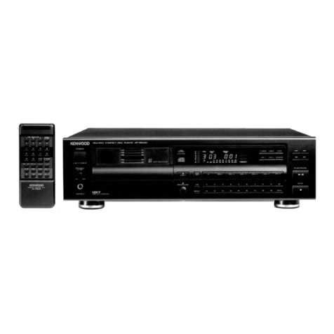
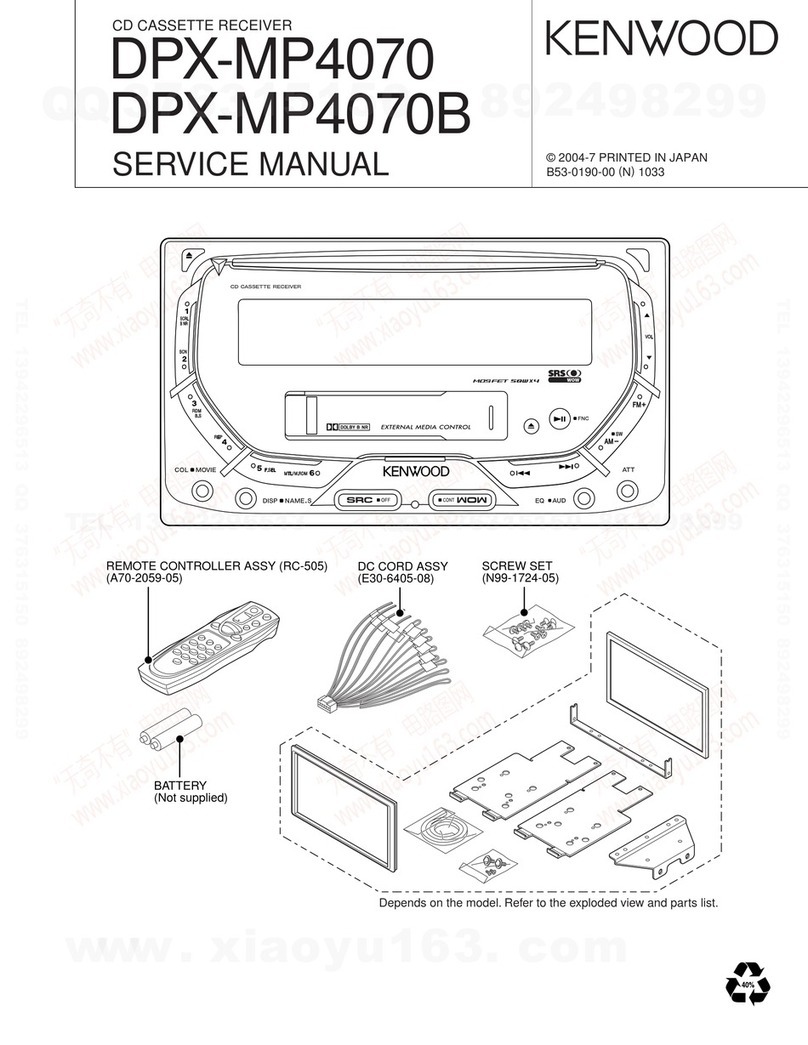
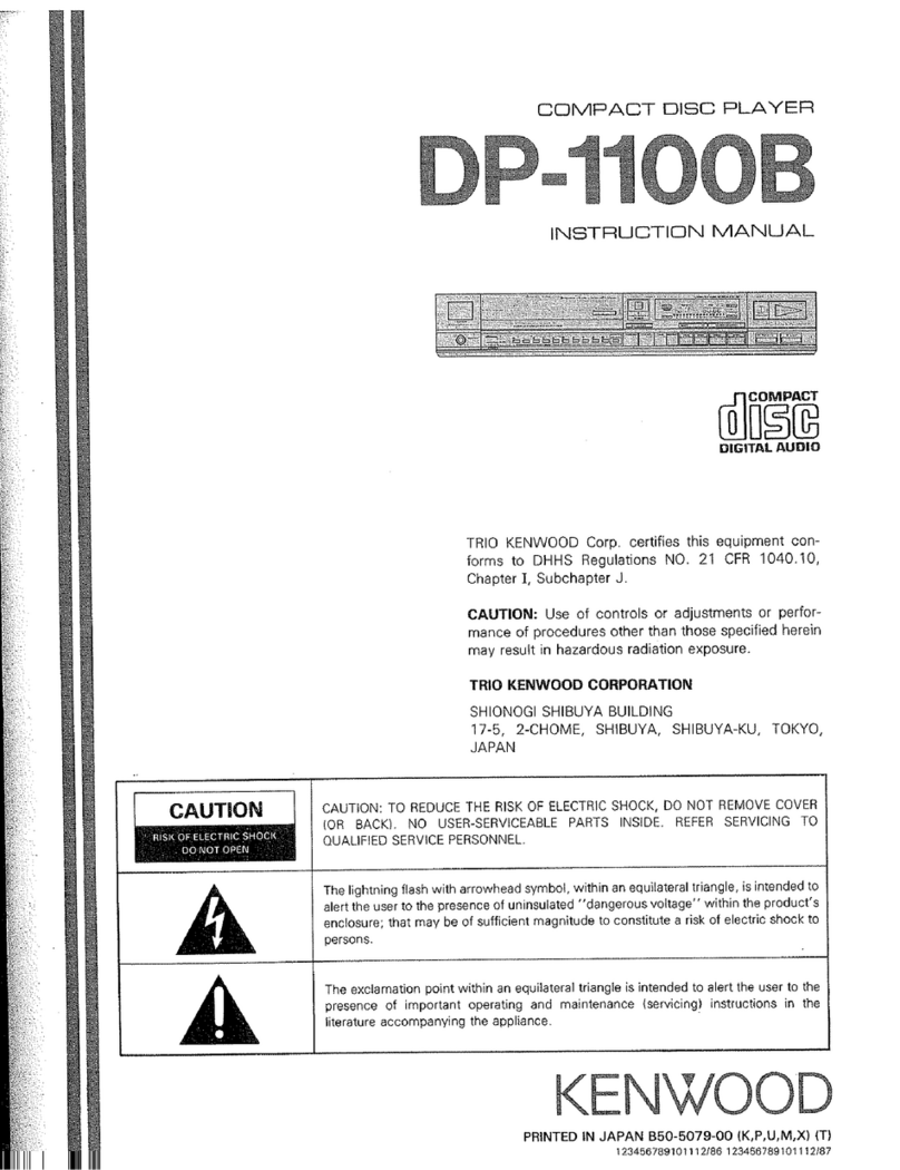
Kenwood DP-7010 User manual

COMPACT
DISC
PLAYER
DP-7010
SERVICE
MANUAL
KENWOOD
(©1989-2
PRINTED
IN
JAPAN
B51-3677-00(0)2842
Panel
(Tray)
Metallic
cabinet
(A29-0139-03)
(A01-1514-02)
Knob
(POWER)
Panel
ass'y*
Knob
(1~20)
(K29-3363-14)
(A20-)
(K29-3493-04)
x
20
Insulator
ass'y
(Front,
Rear
L)
Front
glass
Phone
jack
(PHONES)
Remoto
controller
ass'y
(J02-0397-15)
x
3
(B10-0979-13)
(E11-0190-05)
(A70-0251-05)
Phono
jack
(LINE
OUTPUT)
Transmitting
ass'y
(OPTICAL)
DIGITAL
OUTPUT
Power
cord
bushing
AC
power
cord*
(E13-0483-05)
(W02-0936-05)
(J42-0083-05)
(E30-)
ting
9)
poe
i
CJ
AC
110-120V~
«em
AC
220-240V~
[
Optica
@|
a
Cap
(B09-0068-05)
Insulator
ass'y
(Rear
R)
Phono
jack
(COAXIAL)
DIGITAL
OUTPUT
Slide
switch
(Power
type)*
(J02-0396-15)
(E13-0137-05)
(S31-2128-05)
In
cormplicance
with Federal
Regulations,
following
are
reproduc-
*
Refer
to
parts
list
on
page
71.
tions
of
labels
on,
or
inside
the
product
relating
to
laser
product
safety.
KENW/OOD-Corp.
certifies
this
equipment
conforms
to
DHHS
Regulations
No.
21
CFR
1040.
10,
Chapter
1,
Subchapter
J.
DANGER
:
Laser
radiation
when
open
and
interlock
defeated.
AVOID
DIRECT
EXPOSURE
TO
BEAM.
DP-7010
DP-7010
CONTENTS
CONTROLS
AND
INDICATORS
CONTROLS
AND
INDICATORS
............sscsssssesssseenes
3
9.
18-bit
serial
input
D/A
converter
PCM58P
aaa
\
SYSTEM
CONNECTIONS
.........c:csscsssssesccsssssssersseeees
4
(XB2-137X-XX
2
1CT,B)
...ccsecsssseessecerssecereeeenee
34
H
4
DISASSEMBLY
FOR
REPAIR
10.
8x
over-sampling
digital
filter
SM5813AP
Plopien
Sher
erat
Poe
vie
i
1.
Removing
the
operation
unit....
(X32-137X-XX
2
1014)...
ccsesssessseesseeserveeses
36
:
TOTAL
TIME
Music
calendar
(1
-
20)
‘
2.
Removing
the
tray
...
eine
8
11.
D.P.A.C
IC
TC17GO08AF-8060
:
INDEX
No.
indicator
Output
level
indicator
3.
Installing
the
tray
.....
9
(X32-137X-XX
:
1C19)....
42
!
:
4.
Removing
the
pickup...
10
MECHANISM
OPERATION
DESCRIPTION
46
:
Program
No.
indicator
:
BLOCK
DIAGRAM........
ae
1
1.
Tray
OPEN/CLOSE
operation.......
47
:
CIRCUIT
DESCRIPTION
2.
Pickup
chassis
UP/DOWN
movement
.......47
'
Tanck
NOV
noex
au
wo
ee
Ta]
seme
;
1.
Description
of
components.
.................:.00
13
3.
Gear
installing
position
.................cceeeeee
48
STRACK
No.
indicator
a
we
a
}
ae.
ta
-}
H
Fa
'
2.
CD
player
unit
(X32-137X-XX)
ccsccsscsese
15.
ADJUSTMENT...
PC
ter
th
Eh:
Eh
Ee)
(8)
fo}
3.
Set
mode
flOWChALt
sccscsscsscsctcteneecesee
17.
__—-
REGLAGE
preg
iar
a
pacers
(4)
[42]
(13)
(44)
[5
A.
Test
mode
.ecssesssssssssssssssscesssssssssssssnseneesseseees
18
ABGLEICH
occcscccssssscsssscssssssssssssssscsssessecsssssssseesee
1
Dise-outindicator
(Lis)
(47)
Ga)
[19]
20}
5,
Microprocessor
:PD75212ACW-052
PC
BOARD
(COMPONENT
SIDE
VIEW)
...............
55
:
’
(XB2-137X-XX
|
ICG)
...eseesecosesccsssescsssssrseeneee
24
PC
BOARD
(FOIL
SIDE
VIEW)
1
DISCncicator
‘
6.
RF
AMP.
CXA1081M
(X29-1890-05
:
1C1)...
26
SCHEMATIC
DIAGRAM
‘
‘
7.
Servo
control
CXA1244S
EXPLODED
VIEW
(MECHANISM)
...........s+sssssssssss
6
|:
REPEAT
inaieater
;
(XB2-137X-XX
2
ICO)
cscssescccosssssssensseseesssees
28
EXPLODED
VIEW
(UNIT)
........ssssssssescsssessosecssseesess
7m
Siesan
repeat
idienter
satiate
8.
Digital
signal
processor
CXD11250Z
PARTS
LIST
\
:
'
(X32-137X-XX
+
1CZO)
aecccesscccosscscccsonsesessnsess
31
SPECIFICATIONS
on
EMPHASIS
indicator
EDIT
indicator
'
fo
<
Ties
tea
totale
deh
data
a
nace!
cinta
hie
ata
So
as
oh
age
a
cectee,
de
ae
ose
ee
Ss
J
Disc
tray
Remote
control
light
|
Numeric
keys
([1]-
[20/0].
[+10])
receiving
section
KENWOOD
coved
omc
eaves
of
70°6
STOP
key
(im)
SKIP
keys
((i@@]
.
[pei])
POWER
switch
OPEN/CLOSE
key
([4))
Play
mode
selector
PLAY/PAUSE
key
({E=>]}
(TRACK
mode,
PROGRAM
mode.
TIME
mode,
SINGLE
mode)
Play/pause
indicator
Manual
search
keys
(
(«<j
:
|
)
TIME
DISP.
REPEAT
OUTPUT
LEVEL
a&
CHECK
CLEAR
SPACE
EDIT
EDIT
key
SPACE
key
REPEAT
key
OUTPUT
LEVEL
keys
({¥}.
[a])
CLEAR
key
Time
display
key
CHECK
key
DP-7010
SYSTEM
CONNECTIONS
Do
not
put
the
plug
into
the
socket
until
the
connecting
is
completed.
Connect
having
selected
one
of
@.
®
or
©
below.
Also
refer
to
the
manual
for
the
amplifier
to
which
the
connection
is
to
be
made.
An
accessory
audio
cord
7
Amplifier
An
optical
fiber
cable
DIGITAL
IN
OPTICAL
COAXIAL
AC
voltage
selector
switch
(except
for
some
areas)
DP-7010
To
wali
AC
outlet
A
digital
connecting
cord
DIGITAL
OUTPUT
OPTICAL
COAXIAL
G0
Remove
the
caps.
When
using
digital
output
terminals,
re-
move
the
protective
caps.
m
Conventional
amplifier
connection
(@)
Connect
output
terminal
(LINE
OUTPUT)
@
or
@
tothe
CD
input
terminal
of
the
amplifier
with
the
accessory
audio
cord
supplied.
@
Connection
to
an
amplifier
equipped
with
digital
input
(®
or
©)
Connect
COAXIAL
input
terminal
of
the
amplifier
to
the
DIGITAL
OUTPUT
COAXIAL
@
with
a
digital
cord.
or
connect
OPTICAL
input
terminal
of
the
amplifier
to
the
DIGITAL
OUTPUT
OPTICAL
@
with
an
optical
fiber
cable.
@
Fixed
output
(FIXED):
Output
voltage
is
fixed
to
2
Vrms.
Use
these
stereo
output
jacks
for
connection
to
@
typical
amplifier
or
receiver.
@
Variable
output
(VARIABLE)
.
The
output
level
of
the
head
phones
and
the
VARIABLE
output
lavel
can
be
changed
simultaneously
by
means
of
the
OUTPUT
LEVEL
keys
on
the
front
(.¥,.
[a))
or
remote
control.
The
output
levels
are
indicated
on
the
display.
Use
this
when
you
want
to
match
the
output
levels
with
other
equipment.
“
@
DIGITAL
OUTPUT
COAXIAL
This
terminal
is
for
outputting
the
audio
signals
in
the
original
digital
code.
Do
not
connect
it
to
anything
other
then
the
digital
input
terminal
of
the
amplifier
because
this
could
risk
damag-
ing
the
amplifier
and
speaker.
@
DIGITAL
OUTPUT
OPTICAL
This
terminal
is
for
converting
and
outputting
the
audio
signals
from
digital
to
optical.
Connect
it
to
the
digital
amplifier
attached
to
the
optical
input
terminal.
When
using
this
terminal.
remove
the
protective
cap.
SYSTEM
CONNECTIONS
OUTPUT
LEVEL
keys
([¥]
.[4])
KENWOOD
cowacr
se
ace
oro
Damper
Viewed
from
the
side
Hard
surface
Strut
suspension
Strut
suspension
adjustment
Dampers
are
provided
on
the
4
legs
of
this
unit
for
the
strut
suspension
{see
figure
above).
The
suspension
can
be
adjusted
by
attachment
or
removal
of
these
dampers.
Use
them
if
you
feel
they
are
required
for
sound
quality.
Turn
the
unit
over
when
attaching
or
removing
the
dampers.
We
recommend
that
you
do
not
place
other
components
on
top
of
this
unit
as
it
will
impair
the
suspension
effect.
@
Connecting
optical
fiber
cable
1.
When
connecting
the
optical
cable,
insert
it
straight
until
you
hear
it
click
into
place.
2.
Never
bend
or
tie
the
optical
fiber
cable.
Optical
fiber
cable
AK
©
-O-
3.
Not
all
optical
cables
available
on
the
market
can
be
used.
If
you
cannot
connect
up,
consult
the
store
where
you
bought
it
from
or
your
nearest
sales
outlet.
@
Connecting
power
cord
it
is
useful
to
connect
the
power
cord
for
this
unit
to
the
linking
power
socket
(SWITCHED)
of
an
amplifier.
(Except
for
some
areas)
PHONES
|
j
lv
OUTPUT
LEVELA
a
cae
|
|
Using
stereo
headphones
I
Plug
the
stereo
headphone
into
the
PHONES
terminal
and
.
adjust
with
the
OUTPUT
LEVEL
keys
(¥!,
@
to
get
the
desired
volume.
;
DP-7010
DP-7010
DISASSEMBLY
FOR
REPAIR
DISASSEMBLY
FOR
REPAIR
Remove
the
two
screws
(@),
then
disconnect
the
flexible
board
(@)
and
the
headphone
cable
(O)
from
their
connectors
on
the
main
board,
and
take
out
the
sub
panel
in
the
direction
of
the
arrow
towards
you.
1.
Removing
of
the
operation
unit
4.
*
Take
out
the
case
beforehand.
1.
Undo
the
two
catches
(@)
of
the
tray
panel,
then
detach
the
tray
panel
sliding
it
upwards
(@).
5.
Remove
the
three
screws
(@)
and
undo
the
six
catches
(
@),
then
take
out
the
operation
unit
in
the
direction
of
an
arrow.
2.
Push
in
the
tray
in
the
direction
of
arrow
|
@).
3.
Remove
the
four
screws
(
@)
in
the
downside
of
the
panel
and
the
two
screws
(@)
in
the
upside
of
the
panel,
then
undo
the
two
catches
(
@)
in
the
upside,
and
take
out
the
front
panel
in
the
direction
of
an
arrow
towards
you.
DP-7010
DISASSEMBLY
FOR
REPAIR
2.
Removing
the
tray
1,
With
the
tray
open,
turn
off
the
power
beforehand.
2.
Push
in
the
tray
slowly
by
a
hand
(@).
In
this
situation,
the
gear
is
free
(@).
3.
Push
the
tray
towards
you
and
draw
out
the
tray
(
@).
4.
Push
down
off
the
two
catches
(@)
of
the
tray
stopper,
and
draw
out
the
tray
in
the
direction
of
an
arrow.
5.
When
removing
the
tray,
detach
it
in
the
direction
of
arrow
{@)
in
which
it
can
be
detached
without
the
sub
panel
caught
by
the
tray
stopper.
2-1.
When
the
power
is
not
turned
on
or
when
the
1.
=
Nn
.
Thereby,
the
gear
will
be
free
with
the
tray
slightly
.
Installing
the
tray
.
Set
to
location
(
@)
the
protrusion
on
the
upper
side
DISASSEMBLY
FOR
REPAIR
tray
does
not
come
out
even
by
pressing
the
OPEN
key
Push
the
lever
by
a
screwdriver,
etc.
put
in
through
a
slit
on
the
bottom
plate
of
the
product
as
shown
on
the
right
(@).
advanced.
Thus,
draw
out
the
tray
towards
you
(@).
Otherwise,
as
previously
stated
in
step
3.
of
''2.
Removing
the
tray'’,
push
the
tray
towards
you
and
draw
out
the
tray.
of
the
gear
as
shown
on
the
right.
Push
in
the
tray
along
the
left
and
right
guides.
DP-7010
DP-7010
DISASSEMBLY
FOR
REPAIR
4.
Removing
the
pickup
*
Take
out
the
tray
beforehand.
1.
Remove
the
two
screws
(@),
then
take
out
the
metal
piece
of
the
clamper
in
the
direction
of
the
arrow.
2.
Remove
the
cut
washer,
then
take
out
the
gear
(
@).
3.
Detach
the
two
fixtures
(
@).
Note
1:
When
installing
the
pickup
Perform
the
installation
in
such
a
manner
that
the
metal
piece
comes
into
engagement
with
the
guide
section
of
the
pickup
(
@).
Separate
the
parallel
cords
running
out
of
the
pickup
as
much
away
from
each
other
as
possible
(
©).
Note
2
:
When
replacing
the
pickup
As
to
the
pickup
(J91-0372-05)
supplied
as
a
service
part,
its
LD
short
land
(@)
is
solder-shorted
for
the
laser
diode
(LD)
protection.
Thus
when
replacing
the
pickup,
unsolder
the
LD
short
land
after
the
connec-
tion
with
the
connector.
Wire
clamper
DP-7010
D
BLOCK
DIAGRA
CONTROL
CIRCUIT
UNIT
(X29-1890-05)
CD
PLAYER
UNIT
(X32-137X-XX)
|
ALPC
[oS
ee
—
poe
ee
Fl
Tg
Ce
pe
eae
ee
eee
yg
+5V
“|
RFO
RFI
[
LC1/2),
042
1c168
e
|
|
7,8
WAVEFORM
EFM
SHAPER
DECODER
|
MIRR
DETECTOR
FOK
DETECTOR
DEINTERLEAVE
TIME
BASE-~
GENERATOR
TIME
BASE-
CORRECTOR
SIGNAL
PROCESSING
SYSTEM
CONTROL
E,F
DETECTOR
FRAME
SYNC
DECODER
SUBCODE
OECODER
TRACKING
COUNTER
BUS
INTERFACE
7
SENSE
FOK
Ict6
(pPD75212ACW-052)
MICROPROCESSOR
Ll
ASG:
18.20
i
IC10
(CXA1244S)
1ctS(2/2),
z
z
LOMBARATOR
Q1,2
4
bo
F.C
DRIVER
|%
a
ww
w
-
ie
LP
jouteur
Dn
INTERFACE
T2c
COMPARATOR
12
FASTFEED
Q41
(STA34IM)
1¢22(2/2)
6
4
i¢
6
T.C
DRIVER
FM
(FEED
MOTOR)
7
3
ORIVER
Ici5(t/2)
TM
(
TRAY
MOTOR)
8
2
|
2,3
TRAY
DRIVER
O.M
(
)
(DISC
MOTOR}
CLV
DRIVER
IchH{2/2)
Q3,4
ee
SS
A
eS
0
DP-
7010
CK
DIAGRAM
)
{C14
(SM5813AP)
ICI9
D.P.A.C.
DIGITAL
PULSE
AXIS
CONTROL
OIL
DLO
DIGITAL
FILTER
OIN
DOL
DEINTERLEAVE
TIME
BASE-
GENERATOR
TIME
BASE-
DATA
INTER-
POLATION
OoR
DIR
AMP21
OLR
CORRECTOR
SIGNAL
PROCESSING
SYSTEM
CONTROL
MASTER
CLOCK
GENERATOR
CIRC
ERROR
q
16.9344MHz
T
CORRECTION
1022
(172)
31,32
VRS
23,24
VOL.
UP/OOWN
©)
7,10
37,38
Q33~35
-_{F]
0
Icl6é
(yPO752IZACW-052)
MICROPROCESSOR
35,36
QI7
13
RMUT
sw
(8)
1@~20
9
ee
Ic?
{c3
Ics
1c5
(PCMS8P}
(172)
(172)
{2/72)
e
LINE
eae
ev
LPF
OuT
CONVERTER
CON.
AMP
1c8
1c2
1c4
(PCM58P)
(172)
(172)
/
-
LINE
Oo”
tv
LPF
OUT
CONVERTER
CON.
AMP
1c4
(272)
Ic!
(TC74HCOOP)
DIGITAL
OUT
AMP
OPERATION
UNIT
(X25-3510-01)
|
[-
Page
ee
oe
eet
FL
KEY
OISPLAY
MATRIX
VRT7
REMOTE
CONTROL
SS
Sg
ee
ee
eee
eo
a
ae
ae
oe
+5V
+5V
-l2V +12V
ANALOG
-12V
+7.5V
+5V
-30V
3v
>
0
'
DIGITAL
POWER
SUPPLY
LINE
OUTIL)
FIXEO
VARIABLE
©
1c
3(2/2)
Q19,20
p
-
HEADHONES
AMP
e
O
1c2¢2/2)
Q20,22
LINE
OUTIR)
FIXED
Seba
eee
hoe
ew
VARIABLE
O
OIGITAL
OUT
COAX
TAL
OP-7010
12
DP-7010
CIRCUIT
DESCRIPTION
1.
Description
of
components
1-1,
OPERATION
UNIT
(X25-3510-01}
Ref.
No.
Part
No.
Use/Function
Operation/Condition/Compatibility
1C1
LB1433N
|
Level
meter
IC
FL
tube
level
indicator
driver.
rai
2SC3666
Ripple
filter
+5.6V
regulated
power
supply.
Q2~6
DTC124EN
Digital
transistors
Level
indicator
selection
switch.
Q7~11
2S$C1740S(Q,R}
Drivers
Drivers
of
grids
G2,
G3,
G4,
G5
and
G8.
Q12~15
2SC1740S(Q,R)}
Orivers
1-2.
CONTROL
CIRCUIT
UNIT
(X29-1890-05)
Drivers
of
each
mode
lamp.
Part
No.
Use/Function
Operation/Condition/Compatibility
C1
CXA1081M
RF
amplifier
Generation
of
focus
error
signal,
generation
of
tracking
error
signal,
generation
of
RF
signal
and
its
phase
compensation,
and
auto
asymme-
try
correction.
2SA1426
LD
switch
Laser
diode
B
line
supply
switch.
2SC945(AQ,P)
FE
switch
—T
Focus
error
amplifier
bias
selection
switch.
1-3.
CD
PLAYER
UNIT
(X32-137X-XX)
0-11:
,P
0-21:
U,M,UE
2-71:
X,T.E
Ref.
No.
Part
No.
Use/Function
Operation/Condition/Compatibility
ICt
TC74HCOOP
Digital
out
driver
Digital
output
buffer
amplifier,
and
power
ON/OFF
reset
signal
genera-
tion.
1€2,3
NJM4565D
LV
conversion
(1/2)
:
Conversion
of
D/A
converter
current
output
into
a
voltage
form.
(2/2)
:
Headphone
amplifier.
IC4
NJM4565D
Operation
amplifier
(1/2)
:
Roh
20kHz
LPF.
(2/2)
:
Reh
output
buffer
amplifier.
1c5
NJM4565D
Operation
amplifier
(1/2)
:
Leh
20kHz
LPF
{2/2)
:
Lch
output
buffer
amplifier.
Icé6
M5218P
Operation
amplifier
Error
amplifier
of
+12V
regulated
power
supply.
IC7,8
PCM58P
O/A
converter
Conversion
of
18-bit
digital
data
into
an
analog
form.
Ico
M§218P
Operation
amplifier
{1/2)
:
Error
amplifier
of
-12V
regulated
power
supply.
{2/2)
:
Error
amplifier
of
+5V
regulated
power
supply.
1C10
CXA1244S
Servo
IC
For
each
of
focus,
tracking
and
sled
servo
controls.
Ic11
~
|
NUM4558D
PLL
(1/2)
:
The
phase
comparison
signal
from
pin
11
(PDO)
of
the
digital
signal
processing
LSI
(CXD1125Q2Z)
is
input
in
try
state,
and
this
!C
controls
the
varicap
voltage
by
that
output.
CLV
servo
(2/2)
:
This
IC
controls
the
disc
motor
speed
by
four
outputs
MON,
MDP,
MDS
and
FSW
of
the
digital
signal
processing
LSI
(CXD1125Q2).
MON
.....
Disc
motor
ON/OFF
Disc
motor
rough
control
and
phase
control
|
Disc
motor
speed
control
FSW.....
Disc
motor
filter
time
constant
selection
IC12
M5218P
Operation
amplifier
Error
amplifier
of
+5V
regulated
power
supply
(for
IC19
(D.P.A.C)).
IC13
TC74HCO4P
Clock
pulse
oscillation
Generation
of
master
clock
pulse
(16.9344MHz).
C14
|
SM5813AP
Digital
filter
8x
over-sampling
(18-bit).
IC15
NJM4558D
Operation
amplifier
(1/2)
:
Tray
OPEN/CLOSE
voltage
control.
|=
(2/2)
:
Focus
actuator
phase
compensation
amplifier.
IC16
wPD75212ACW-052
|
Microprocessor
Display,
each
key
input
process
and
servo
IC
control.
(C18
CXK5816SP-15L
Static
RAM
EFM
demodulation
data
time
axis
correction
16K
S-RAM.
{C19
TC17G008AF-8060
O.P.A.C
|_
Digital
Pulse
Axis
Control
(Refer
to
page
42.}.
1C20
CXD11250
Digitat
signal
processing
IC
Bit
clock
pulse
regeneration
by
EFM-PLL
circuit,
EFM
data
demodula-
C€XD11250Z
tion,
and
frame
sync
signal
detection,
protection
and
interpolation.
1C22
NJM4558D
Operation
amplifier
(1/2)
;
Electrically
driven
VR
up/down
voitage
generation.
190)
.
Trasking
actustar
deve
bother
13
14
DP-7010
CIRCUIT
DESCRIPTION
Ref.
No.
Part
No.
Use/Function
Operation/Condition/Compatibility
Qi
288941
|
Driver
Focus
actuator
drive
current
booster.
Q2
|
2SC3940A
Driver
|
Focus
actuator
drive
current
booster.
Q3
2SD1266(Q,P)
Driver
Disc
motor
drive
current
booster.
Q4
2SA1534A
Driver
Disc
motor
drive
current
booster.
a5
DTC124EN
Switch
Controls
the
bias
switch
of
the
focus
error
signal
by
signal
SENS,
and
also
controls
the
focus
gains
FS3
of
the
servo
IC.
a6
2SK246(Y,GR)
Switch
Controlled
by
the
defect
control
switch
(Q8).
When
flaw
is
detected,
06
turns
OFF
to
open
the
focus
servo
loop.
|
Q7
2SK246(Y,GR}
{
Switch
Controlled
by
the
defect
control
switch
(Q8)
in
the
same
manner
as
Q6.
When
flaw
is
detected,
Q7
turns
OFF
to
open
the
tracking
servo
loop.
as
2SA733(AN(Q,P)
Switch
Controls
the
defect
detection
switch,
and
the
switches
Q6
and
Q7
for
2SA933S(Q,R)
focus
and
tracking
errors.
When
flaw
is
detected
:
OFF,
At
normal
play
:
ON
(Inverted
logic
of
signal
DEFECT)
ag
2SC945(A}(Q,P)
;
Switch
Inputs
the
tracking
error
signal
to
pin
ATSC
(anti-shock)
through
BPF
to
28C€1740S(Q,R)
prevent
sound
jump
due
to
shock
by
external
disturbance.
Q10
2SA733(ANQ,P)
Power
supply
FL
tube
reference
voltage
supply
{(-30V).
2SA933S(Q,R)
Qi1
2SA1534A
Power
supply
FL
tube
reference
voltage
supply
(-30V).
|
Q12
2SA733(A)(Q,P)
Power
supply
-5V
digital
power
error
amplifier.
2SA933S(Q,R}
Q13,14
2SA954(L,K)
Ripple
filter
For
-5V
regulated
power
supply.
Q15,16
2SC945(ANQ,
P)
Reset
Power
ON/OFF
reset
pulse
generation.
2SC1740S(Q,R)
Q17
2SA733(AQ,P)
Switch
Output
muting
relay
driver.
Q18
2SC2003(L,K)
i
Ripple
filter
For
+12V
regulated
power
supply.
Q19
2SC2003(L,K)
}
Oriver
Headphone
amplifier
driver
(Lch).
|.a20
|
2scz003(L.K)
|
Driver
|
Headphone
amplifier
driver
(Roh).
Q30
2SA954(L,K)
Ripple
filter
For
-12V
regulated
power
supply.
Q31
2SC3666
Driver
Electrically
driven
VR
current
booster.
Q32
2SA1426
Driver
Electrically
driven
VR
current
booster.
033,34
2S8C2878(B)
Switch
De-emphasis
switch,
which
is
controlled
by
digital
transistor
Q35.
{De-emphasis
“'H"
:
ON)
Q35
DTA124EN
Digital
transistor
switch
Controlled
by
pin
14
of
microprocessor.
{At
emphasis
:
ON)
Q36
2SB722(Q,P,E)
|
Ripple
filter
For
+5V
regulated
power
supply.
Q37
2SC2003{L,
K)
Ripple
filter
For
+5V
regulated
power
supply
(for
D.P.A.C).
Q38
|
2SD1266(Q,P)}
i
Ripple
filter
For
+5V
regulated
power
supply.
a39
2SD1266(Q,P)
i
Ripple
filter
For
+7.5V
regulated
power
supply.
2SC2003iL,K}
|
Ripple
filter
For
-12V
regulated
power
supply.
Q41
STA341M
Driver
(1/3)
:
Tray
motor
driver.
!
(2/3)
:
Feed
motor
driver.
(3/3)
:
Tracking
coil
driver.
DP-7010
CIRCUIT
DESCRIPTION
2.
CD
player
unit
(X32-137X-XX)
+
D.P.A.C
(Digital
Pulse
Axis
Control)
circuit
Two
different
distortions
are
attendant
on
the
con-
version
of
the
digital
signal
into
an
analog
signal.
One
is
a
distortion
on
the
level
axis
(voltage
axis),
which
is
determined
mainly
by
the
resolution
of
the
D/A
con-
verter,
and
in
case
of
using
a
ladder
resistor
type,
by
its
error,
The
other
is
a
distortion
on
the
time
axis,
which
is
not
so
prevailing
as
to
appear
on
the
distortion
meter
but
has
e————-€
Original
Sound
. —
—.__
x
Regenerated
ms
*
Waveform
Fig.
2-1
Error
(distortion)
on
voltage
axis
Next,
let
us
deal
with
the
theory
of
the
D.P.A.C
operation
by
a
basic
D.P.A.C
circuit
of
this
time.
Also
when
the
latch
signal
©
from
the
digital
filter
is
disturbed,
an
accurate
latch
signal
like
©
can
be
ob-
Latch
signal
(WCKO)
from
digital
filter.
©
8.4672MHz
great
influence
on
the
sound
quality.
It
is
the
D.P.A.C
that
is
to
operate
as
a
circuit
to
improve
this
point.
Figure
2-1
shows
the
error
(distortion)
on
the
voltage
axis
of
the
D/A
converter
output
for
the
original
sound,
and
Figure
2-2
shows
the
error
(distortion)
on
the
time
axis
of
the
D/A
converter
output
for
the
original
sound.
As
seen
from
this,
even
with
a
variation
in
time
axis,
there
appears
a
regenerated
waveform
different
from
the
original
sound.
e——————-@
Origina!
Sound
Regenerated
Woveform
Fig.
2-2
Error
(distortion)
on
time
axis
tained
at
the
rise
of
the
master
clock
pulse
©).
By
virtue
of
this
latch
signal,
a
proper
voltage
signal
is
output
from
the
D/A
converter.
Latch
signs
[>
to
D/A
converter.
8
AGT2MHz
I
®
H
‘
I
Latch
signal
from
digital
filter.
1
\
‘
{8.4672MHz}
1
1
‘
:
\
I
!
Master
clock
pulse.
(16.9344MH2)
H +
©
Latch
signal
to
D/A
converter.
(8.4672MH2)
Fig.
2-3
D.P.A.C
basic
circuit
DP-7010
CIRCUIT
DESCRIPTION
Let
us
show
the
signal
timing
in
a
practical
circuit.
SIGNAL
PROCESSOR
toxo112802)
iaecogas
DVA
CONVERTER
3
‘I
DOPAC
{1C17G00RAF
80601
Fig.
2-4
Signal
:
1kHz,
Od8
{at
play)
o
800
1600
2400
3200
4000
4800
$600
ns
p++
+++
+
+++
++
+++
t+
-++
:
LJ
Chan.
1
(XAT)
he
;
*
Chaput
to
dia
ter
Data
is
read
Lich
data
Chan.
3
1LRCK}
at
rising
edge
iC
ce
ee
ce
ae
ee
en
ee
eee
"
Chan.
5
(XTIFS192)
Chan.
6
(WFS)
\
Sil
a
i
7wock)
|
DP.Ac
?
Serial
data
nput
Chan.
8
(DIL?
Chan.
9
(DIR?
Z
’
;
44
i
weed
ti
T
chan.
11
(wocko)
|
Cian
I
(Tuning
of
serial
data
it
Leh
1
(
output
from
OPAC
H
nm
mon
eee
ie
ies
ravo1Lo)
|
|
eae
ers
!
}
}
}
st
}
|
Chan.
13
(DINO)
2
Time:
2us
Teg
Chan.2
Levelt
(AUTO)
Zoom
x5
16
Fig.
2-5
D.P.A.C
timing
chart
DP-7010
CIRCUIT
DESCRIPTION
3.
Set
mode
flowchart
3-1.
Outline
after
POWER
ON
POWER
ON
500ms
wait
FL
lights.
Disc
motor
starts
to
rotate.
Pickup
is
returned
inwards.
(Pickup
positioning}
Tracking
ON
GFS
|ehacisring
|
Yes
Feed
motor
ON
Ti
letely
Z>
Is
FOK
signal
"H"?
The
head
of
1st
music
is
searched
for
and
is
played.
Disc
motor
is
braked.
Focus
search
made
3
times?
SENSE
signal
chattering
eliminated.
500us
YES
"Disc
OUT”
Disc
motor
stops.
is
displayed.
7
DP-7010
DP-7010
CIRCUIT
DESCRIPTION
CIRCUIT
DESCRIPTION
4.
Test
mode
4-1.
Setting
the
test
mode
4-2.
Key
and
functions
valid
in
thst
mode
, t
Function
Track
No.
displey
Unlike
previous
models,
this
microprocessor
can
be
put
(1)
Focusing
servo...
2...
--6--
ON.
zi
—
to
the
test
mode
by
just
short-circuiting
the
test
pins
even
(2)
Trackingservo..
2.0.
ee
ON.
mM
in
the
set
mode
(normal
condition).
(However,
the
disc
(3)
Feedservo.....-...000-6-
ON.
Li
must
be
present
in
the
unit.)
PLAY
4
The
test
mode
can
also
be
initiated
with
the
previous
method,
i.
e.
by
switching
the
power
on
with
the
test
pins
short-circuited.
Displayed
for
a
few
seconds
after
comple-
tion
of
(1),
(2)
and
(3).
4
Disc
Track
No.
is
displayed.
(1)
Focusing
servo...
2...
ees
ON.
rm
—,
CHECK
(2)
Tracking
servo...
2...
2-45-55
OFF.
!
_!
(3)
Feed
servo...
2.2.
eee
OFF.
_t
_!
(1)
Focusing
servo
2...
ee
ee
ON.
mn
(2)
Tracking
servo...
2
ee
ee
ON.
Li
L/
(3)
Feedservo.......-.------
OFF.
pet
+
{1)
Focusingservo
.....-.-----
OFF.
i]
n
(2)
Tracking
servo...
2...
-
20
eee
OFF,
!
I
{3)
Feed
servo...
.-.---
++
eee
OFF.
uu
!
T
NO,
“01”
is
displayed.
CU
Tray"
uo
hk
ESE,
Begs,
bE
REPEAT
The
REPEAT
function
is
canceled
when
the
tray
is
closed
by
pressing
the
tray.
;
net
The
Track
No.
disptay
L/
/
.
In
the
STOP
mode,
moves
the
pickup
slightly
toward
the
outer
>>
position
of
disc.
When
feed
servo
is
ON,
sets
the
track
gain
to
"H"’.
In
the
STOP
mode,
moves
the
pickup
slightly
toward
the
inner
Position
of
disc.
When
feed
servo
is
ON,
sets
the
track
gain
to
“L"’.
Turns
ail
FL
display
lamps
ON.
__|
Turns
alt
FL
display
lamps
OFF.
Jumps
tracks
as
shown
below.
Y'
from
OPEN/CLOSE
eS
Hien
Number
of
tracks
ey
OF
i
PTE
OPEN/CLOSE
Numerie.seY
Direction
key?
(o~
9)
Key
Number
of
tracks
OPEN/CLOSE
T
When
the
tray
is
opened
then
closed,
Track
No.
2,6,
7,8,
10,
13
and
or
+10
|
22
are
programmed
and
the
test
mode
is
canceled.
Track
No.
2, 6,
7,8,
10,
13
and
22
are
programmed
and
the
test
mode
is
canceled.
TNO.
2,6,
7,8,
10,
13
and
22
are
programmed
automatically.
Set
mode
P.
MODE
18
19
DP-7010
20
CIRCUIT
DESCRIPTION
4-3.
Flowchart
of
test
mode
«
Flowchart
from
tray
OPEN
status
after
power
ON
feed
of
PU
01
displayed
in
TNO
200ms
WAIT
Acceptance
of
key
NO
YES
Cancellation
of
tray
CLOSE
Memory
data
store
oe
5
sec.
Fi
elapsed?
Cancellation
of
tray
OPEN
YES
Outward
feed
of
PU
Was
OPEN/
CLOSE
key
Pressed?
SLT:
Pickup
sled
limit
switch
CLS
:
Tray
close
detect
switch
OPEN
:
Tray
open
detect
switch
DP-7010
CIRCUIT
DESCRIPTION
«
Focus
search
&
focus
servo
ON
START
initialization
of
CXA1244S,
€xX011250Z
1.2
sec.
elapsed?
NO
SENSE:
“H”"
continues
0.5msec
on
FOK:“H"?
YES
servo
ON
Disc
motor
ON
21
DP-7010
CIRCUIT
DESCRIPTION
«
Disc
motor
STOP
*
Tracking
servo
ON
Tracking
servo
ON
@
FOK
terminat
Dise
motor
®
terminal
(“SENSE”)
YES
5ms
WAIT
@
FOK
terminal
22
Disc
motor
stop
DP-7010
CIRCUIT
DESCRIPTION
+
In
a
usual
case,
since
the
tray
was
pushed
when
the
tray
is
OPEN
until
STOP
display
is
made.
START
+
From
loading
of
Q
data
to
display
START
H
f
atl
of
YES
Loading
of
al
(®
SLT
terminal
“~~
96
bit
deta
|
YES
@®CRCF
terminal
@®
SLT
terminal
@®
SLT
terminal
Stop
of
PU
23
DP-7010
5.
Microprocessor
uPD75212ACW-052
(X32-137X-XX
:
IC
16)
CIRCUIT
DESCRIPTION
5-1.
Terminal
connection
diagram
1
2
3
4
§
6
7
8
yPD75212ACW-052
24
CIRCUIT
DESCRIPTION
5-2.
Explanation
of
terminals
DP-7010
26
27
28
29
Pin
No.
Pin
Name
(1/0
Function
1~4
d~a
O
|
FL
segment
control
pins
(Also
for
key
scan
signai).
5
SENSE
|_|
Signal
processing,
detection
pin
of
signal
SENSE
from
servo
IC
(FZC,
kick
pulse,
CLV).
6
T
WFCK
|
|
Q
data
read
clock
pulse
input
pin.
SUBO
1
|
Q
data
input
pin.
2
CRCF
|
|
Qdata
CRC
check
result
input
pin.
input
from
digital
signal
processing
LSI
(""H"
:
OK).
RCI
|_|
Remote
control
input
pin.
10
SCOR
|
|
Sub-code
frame
sync
detection
signal
input
pin
{In
sync
;
“'H'’).
11
FOK
1
|
RF
amplifier
FOK
signal
input
pin.
12
GFS
1
|
Frame
sync
signal
input
pin
{in
frame
sync
:
''H").
13
RMUTE
O
|
Analog
mute
control
pin
(Active
"L"').
14
EMPH
O
|
De-emphasis
control
pin
(Active
‘'H’').
|
15
|
DIRC
O
|
Servo
IC
DIRC
pin.
Direct
control
pin
output
(Normally
:
“H'').
16
PLAY
LED
O
|
Play
LED
drive
port.
17
PAUSE
LED
|
O
|
Pause
LED
drive
port.
18
SLTSW
|
|
Sled
limit
switch
(Innermost
:
"L").
19
OPNSW
|_|
Tray
open
switch
(At
open
:
"L").
20
CLSSW
|
|
Tray
close
switch
(At
close
:
"L"’).
21~24
KDO~KD3
|
\
Key
matrix
key
return
input
pins.
25
DATA
©
|
Signal
processing,
servo
JC
control
output
pin.
fe)
ie]
ie)
ie)
vO
i
ae
XLT
CLK
toc
SGLE
Signal
processing,
servo
IC
control
output
pin
(latch).
Signal
processing,
servo
IC
control
output
pin
(clock
pulse).
Laser
ON/OFF
signal
output
pin (Active
‘'L"’).
Signal
mode
lamp
drive
port.
System
clock
pulse
I/O
pin.
~_|
Unused.
Vss
-
|
GND.
Unused.
OPNM
O
|
Tray
motor
OPEN
output
pin.
|
36
|
CLSM
O
|
Tray
motor
CLOSE
output
pin.
37
VOL.
UP
O
|
Volume
UP
output
pin
(for
motor
VR).
38
VOL.
DOWN
|
O
|
Volume
DOWN
output
pin
(for
motor
VR).
39
RESET
|
|
Reset
input
pin.
40~50
G1~G11
O
|
Fl
digit
contro!
output
pins.
$1
LDTM
O
|
Time
mode
LED
drive
port.
52
LDPG
©
|
Program
mode
LED
drive
port.
53
LOTR
O
{|
Track
mode
LED
drive
port.
54,55
Lk
O
|
Fl
segment
control
pins
{also
for
key
scan).
|
56
|
VPRE
-
|
FL
predriver
power
supply.
57
VLOAD
-
|
FL
driver
negative
power
supply
(-30V).
58~63
j~e
©
|
FL
segment
control
output
pins
{also
for
key
scan).
[|
64
|
Voo
-
|
Power
supply
(+5V).
DP-7010
DP-7010
CIRCUIT
DESCRIPTION
CIRCUIT
DESCRIPTION
6.
RF
AMP.
CXA1081M
(X29-1890-05
:
IC1)
6-2.
Explanation
of
terminals
(Vcc
=
2.5V,
VEE
=
DGND
=
-2.5V,
VC
=
GND)
General
Structure
Functor
The
CXAt
eC
081M
is
an
IC
developed
for
use
in
Compact
Disc
Bipolar
silicon
monolsthic
IC
Input
pin
for
the
C-coupled
signa
output
trom
the
RF
summing
amplifier
players.
It
incorporates
a
3-spot
optical
pickup
RF
output
amplifier,
a
focusing
error
amplifier,
a
tracking
error
amplifier,
F
‘i
jan
summing
amplifier
output
pin
Used
as
the
check
port
for
the
eye
pattern
and
other
signal
processing
circustry,
such
as
focus
OK,
mir-
e
RF
amphfier
RF
summing
amplifier
feedback
input
pin
ror,
defect,
and
EFM
comparator
circuits,
as
well
as
a
laser
©
Focus
OK
detector
circuit
P-sub/N-sub
select
pin
for
the
LD
(Laser
Diode)
(DC
vottage’
in
N-sub
mode!
APC
(Aut
diode
APC
{Automatic
Power
Control)
circust
©
Mirror
detector
circuit
*APC
LD
amplifier
output
pin
{OC
voltage:
PO
open
in
N-sub
mode)
©
Tracking
error
amplifier
ABCLD
;
ne
:
I 1 \
Features
©
Defect
detector
circuit
LO:
amnpliber
input.
pin-ADe
volage,
Open
©
Operates
on
a
signal
-
5
V
power
supply,
as
well
as
on
a
©
APC
circuit
RF
|-V
amplifier
(1)
inverted
input
pin
+5
V
dual-voltage
power
supply
©
EFM
comparator
Current
input
by
connecting
to
the
photodiode
A
+
C
terminal
*
Low
power
consumption
(100
mW
with
+5
V,
50
mW
*
Auto
asymmetry
control
amplifier
RF
1-V
amplifier
(2)
inverted
input
pin
with
+5
V}
Current
input
by
connecting
to
the
photodiode
B+
D
terminal
*
An
APC
circuit
which
accepts
esther
a
P-sub
or
N-sub
laser
Connected
to
GND
when
using
a
positive
|
+
)/negative
{~)
dual-voltage
power
supply
diode
Connected
to
VR
(pin
14)
when
using
a
single-voltage
power
supply
¢
A
minimum
of
external
parts
required
FI-V
amplifier
inverted
input
pin
¢
A
disc
defect
detector
circuit
for
improved
playability
Current
input
by
connecting
to
the
photodiode
F
termina!
E
1-V
amplifier
inverted
input
pin
Current
input
by
connecting
to
the
photodiode
E
termina!
E
1-V
amplifier
output
pin
6-1.
Block
diagram
E
I-V
amplifier
feedback
input
pin.
For
E
I-V
amplifier
gain
adjustment
DC
voitage
output
pin
of
(Ver
+
VeeH2
Input
pin
for
the
C-coupled
signai
output
from
the
defect
bottom
hold
Defect
bottom
hold
output
pin
Connected
to
the
negative
power
supply
when
using
a
positive
|
+
}/negative
(—}
dual-voltage
power
supply.
Connected
to
GND
when
using
a
singie-voliage
Dower
supply
Bias
pin
on
the
focus
error
amplifier
non-inverted
side
For
CMR
adjustment
of
the
focus
error
ampiifier
AUTO
ASYMMETRY
Focus
error
amplifier
output
pin
Tracking
error
amplifier
Output
pin
FOoK
amp
IDIFFEREN—
TAL
AMP.
T
DEFECT
Defect
comparator
output
pin
(DC
voltage
connected
to
a
10
k-ohm
load}
MIRR
Mirror
comparator
output
pin
{DC
voltage:
connected
to
a
10
k-onm
load)
Voltage
Reference
Mirror
hold
capacitor
output
pin
Mirror
comparator
non-inverted
input
BOTTOM
HOLD
TRACKING
ERROR
amp
Detect
bottom
hold
capacitor
connect
pin
Connected
to
GND
when
using
a
positive
{
+
l/negative
{~}
dual-voltage
power
supply
Connected
to
GND
(Vee)
when
using
a
single-voltage
power
supply
Auto
asymmetry
control
input
pin
Vernn
—£FM
comparator
output
pin
{DC
voltage’
connected
to
a
10
k-ohm
load)
Vion:
FOK
comparator
output
pin.
(DC
voltage’
connected
to
a
10
k-ohm
load)
RF
tev
AMPLY)
-2.5
LD
ON/OFF
select
pin.
(DC
voltage:
when
LD
ON)
{OGND)
_j—____.
2:5:
Positive
power
supply
“APC:
Automatic
Power
Control
26
a
DP-7010
CIRCUIT
DESCRIPTION
7.
Servo
control
CXA1244S
(X32-137X-XX
:
IC10)
CXA1244S
is
a
bipolar
1C
developed
for
servo
of
compact
disc
(CD)
olayers,
and
it
provides
the
following
functions.
7-1.
Terminal
connection
diagram
OFocus
control
(search
ON/OFF,
gain
control)
OTracking
control
{servo
ON/OFF,
single
track
jump,
a
!
a
multiple
track
jump,
gain
control,
phase
compensation
ps
:
6
control,
brake
circuit)
TEO
4
TAO
©
Sled
control
(servo
ON/OFF,
fast
forward,
fast
SENSE
5
DIRC
reverse)
C.ouT
6
”
25
sL®
Servo
function
of
each
of
focus,
tracking
and
sled
XRST
7
2
24
SsltO
as
well
as
random
access
operation
are
realized
through
DATA
8
py
23
SLO
control
by
microcomputer.
Furthermore,
the
serial
data
XLT
¢
FEO
bus
can
be
shared
with
CXD11250Z.
CLK
oO
FEO
MIRR
FE
ATSC
FS3
VEE
SRCH
7-2.
Block
diagram
GNO
Gt
TAD
~—
TAO
plac
§=6SL@CSLO
SLO
FEO
FEO
FE
ATSC
FS3
VEE
=
SRCH
Tracking
4
TG1
gain
uP/
*
J
NORMAL.
12
r
T™6
yr
y
TMS
Focus
—
?
ON/OFF
GOuA}
6OuA
SLED
‘
Comparator
(1)
ON/OFF
60uA
60uA
Compa-
rator
(4)
<
ie
60uA
30uA
Comparator
(3)
Focus
UP/DOWN
TM1~
TM?
ML
LOGIC
O
d
Tracking
ON/OFF
TG2
TAD
TEO
TEOQ
SENSE
COUT
XRST
DATA
XLT
cKL
MIRA
2c
TE
ISET
vec
28
DP-7010
CIRCUIT
DESCRIPTION
7-3.
Explanation
of
terminals
Terminal
No.
|
Terminal
name
|1/O
Functions
1
'
TG2
Tracking
amplifier
gain
switching
terminal.
GND
level.
2
TA
@)
Non-inverted
input
of
operational
amplifier
2.
3
TEO
it
Output
of
operational
amplifier
4.
4
TEO
|
O_}
Inverted
input
of
operational
amplifier
4.
5
SENSE
©
|
Output
of
SSP
internal
status
that
corresponds
to
ADDAESS
of
CPU
-~
SSP.
|
(Changes
in
accordance
with
ADDRESS
content
of
internal
serial
register.)
See
Note
1.
6
Cc.
OUT
©
|
Signal
output
for
counting
number
of
tracks
at
the
time
of
high
speed
access.
re
XRST
{
|
All
internal
registers
are
cleared
when
CPU
—
SSP
““L”.
Connected
with
CPU
RESET.
See
Note
2.
8
DATA
1
|
Serial
data
transmission
of
CPU
+
SSP.
Input
is
made
from
LSB.
DO~O7.
9
XLT
I
Latch
of
seria!
data
of
CPU
-
SSP,
(The
contents
of
internal
serial
register
are
transmitted
to
each
address
decoded
latch.)
Transmission
at
‘’L’.
Change
to
“H’’
occurs
immediately
after
execution
sett
at
because
no
edge
trigger
is
produced.
10
CLK
|
|
CPU
-
SSP
serial
data
transmission
clock.
Data
is
read
at
falling.
fn
fevel
before
and
after
transmission.
1
MIRR
1
|
Mirror
signal
input
from
RF
amplifier.
12
Tze
|
|
Tracking
error
signal
is
input
with
C
couple.
The
time
constant
is
determined
by
one
single
track
1
jump,
but
it
is
usually
around
2kHz.
13
TE
}
|
|
Tracking
error
signal
input.
14
ISET
i
Setting
of
current
level
for
determining
focus
search
voitage,
|
tracking
jump
voltage
and
sled
feed
voltage.
15
Vee
Power
supply
terminal.
Normally
—5V.
16
SRCH
41
The
capacitor
for
determining
the
time
constant
of
charge/duscharge
waveform
for
focus
search
is
connected.
17
VEE
i
Power
supply
terminal.
Normally
—5V.
18
FS3
i
|
Focus
amplifier
gain
switching
terminal.
GND
level.
19
ATSC
Such
information
that
a
mechanical
shock
was
applied
to
the
player
is
input,
Simply,
a
trakcing
error
is
input
through
B.P.F.
20
FE
|
|
Input
of
focus
error
signal.
21
FEO
O
|
Output
of
operational
amplifier
1.
22
FE
©
1
|
Inverted
input
of
operational
amplifier
1.
23
SLO
|
Output
of
operational
output
3.
24
SL
2)
-|o
inverted
input
of
operational
amplifier
3.
25
sL®
Non-inverted
input
of
operational
amplifier
3.
26
DIRC
Used
at
the
time
of
one
track
jump.
Normally
“’H’’.
The
direction
of
the
track
jump
pulse
is
reversed
with
“L’’.
Setting
is
made
in
the
normal
tracking
mode
by
changing
to
“H”.
i
“L”
for
a
fixed
length
of
time with
detection
of
activation,
deactivation
of
TZC.
TAO
O
|
Output
of
operational
amplifier
2.
TAO
O
|
Inverted
input
of
operational
amplifier
2.
TG
Tracking
amplifier
gain
switching
terminal.
GND
level.
GND
terminal
of
IC.
Note
1:
SENSE
terminal
output
Serial
date]
ADORESS
|
Note
2
:
Digital
unit
timing
chart
a
Focus
|
99090
°
conTROL
4bits|
content
|
termine!
output
T
7
"H"
when
focus
zero
cross,
Focus
erro
vot-
*
tage
1s
OV
or
higher.
|
Used
at
the
time
of
|
FOCUS
PULL
opera.
tion
Laie
Co
Exp
8
oe
oP
Ee
tu
tee
+
TRACKING
|
290%
CONTROL
"M4"
when
the
ATSC
|
snput
tevel
exceeds
tne
AS
wind
comparator
level
){VTM
>
Vee
»
13%)
|
Bur
this
is
Not
used
in
|
ths
eauioment
Data
is
loaded
at
activation
;
CLK
i
|
|
i
TRACKING
|
0019
|
MooE
Judgement
output
of
positive
or
negative
of
>
tracking
zero
cross.
«tracking
error.
T/fek
When
used
at
the
time
%
Re
EI,
twek=-—~
=
twek
—S
-—tiDe-
;
OFAC
1s
reduced
to
of
on
detection
of
Tzc
|
of
single
track
yump,
|
"Lon
detection
of
j72ZC
1.
in
FWO
JUMP
: ,
Execution
of
instruction
TZC
4
in
REV
JUMP
twe
29
DP-7010
CIRCUIT
DESCRIPTION
7-4.
System
contro!
COMMAND
ADDRESS
FOCUS
CONTROL
TRACKING
CONTROL
fou
GAIN
SET
TRACKING
MODE
TRACKING*
GAIN
SET*
TG1,
TG2
may
be
set
independently.
In
the
case
of
ANTI
SHOCK
=
1
(00011XXX),
both
TG1,
TG2
are
inverted
when
ANT!
SCHOCK
=
“H".
SLED
MODE
*
TRACKING
MODE
*
SERVO
ON
SERVO
ON
FWD
MOVE
FWD
JUMP
REV
MOVE
REV
JUMP
30
DP-7010
CIRCUIT
DESCRIPTION
8.
Digital
signal
processor
CXD11250Z
(X32-137X-XX
:
1€20)
General
The
CXD1125QZ
is
a
digital
processing
LSI
for
a
Com-
pact
Disc
player,
and
has
the
following
functions.
1.
Bit
clock
reproduction
by
an
EFM-PLL
circuit
2.
EFM
data
demodulation
3.
Frame
sync
signal
detection,
protection
and
insertion
4.
Powerful
error
detection
and
correction
5.
Interpolation
with
an
average
value,
or
by
holding
the
previous
value
6.
Demodulation
of
a
sub
code
signal,
error
detection
of
a
sub
code
Q
7.
Spindle
motor
CLV
servo
8-1.
Block
diagram
('Z)
scor
asy
Supcece
Sync
Detector
P00
GFS
(6
ie!
Lock
|
Med
CLV
Servo
frame.
3
sync
elector.
tice
Control
protector/inserter
MDS
Ya
won
(2)
vco
taming
generator
X°TAL
circuit
Taming
generotor
cnn
(1?)
Trocking
counter
8.
8-bit
tracking
counter
9.
CPU
interface
with
a
serial
bus
10.
Sub
code
QO
register
11.
Digital
fitter
12.
Digital
audio
interface
output
Features
©
All
digital
signals
used
in
playback
can
be
processed
using
only
a
single
chip
©
An
aperture-correction
digital
filter
1s
built
in
Structure
CMOS
IC
Subcode
Subcode
O
Demodulotor
Register
EFM
Demodulotor
Ercor
Getector
/corrector
Digitat
Fitter
{CX011250Z)
RAM
oddress
Digitet
out
generator
(Cx0112602)
31
DP-7010
DP-7010
CIRCUIT
DESCRIPTION
CIRCUIT
DESCRIPTION
8-2.
Explanation
of
terminals
Function
Address
output
of
external
RAM.
ADORO7
vo
Time
constant
switching
output
of
output
filter
of
spindle
motor
ie)
RAOB
ie)
Address
output
of
external
RAM.
ADDROS
ce)
ce)
fo)
ie)
fe)
ce)
ON/OFF
contro!
output
of
spindle
motor
Address
output
of
external
RAM.
ADDRO9
Address
output
of
external
RAM.
ADDR10
Address
output
of
external
RAM.
ADDR
11
(MSB)
Write
Enable
signal
output
to
external
RAM.
(Active
at
‘'L"’)
Drive
output
of
spindle
motor
Rough
speed
control
in
CLV-S
mode
and
phase
control
in
CLV-P
mode
Orive
output
of
spindle
motor.
Speed
control
in
CLV-P
mode
EFM
signat
input
from
RF
amplifier
Output
for
controlling
the
slice
tevei
of
EFM
signat
Chip
select
signat
output
to
external
RAM.
(Active
at
''L"")
Crystal
dividing
output.
f=
4
2336
MHz
+
+
Samples
the
GFS
signal
with
WFCK/16,
and
outputs
''H’’
when
the
level
is
high
When
itis
‘‘L’’
for
eight
times,
in
arrow,
outputs
““L"’
VCO
output.
f=
8
6436
MHz
when
locked
to
EFM
signal
-
GND
(0
V)
VCO
input
XTAI
i
|
Crystal
oscillator
input.
f=
8
4672
MHz
or
16.9344
MHz
depending
on
the
mode
selected
(OV)
XTAO
O
Crystal
oscillator
output.
f=
8.4672
MHz
or
16.9344
MHz
depending
on
the
mode
selected
+—_—
Phase
comparison
output
of
EFM
signal
and
VCO/2
GND
(0
V)
Serial
data
transmission
clock
input
from
CPU
Data
's
latched
at
rising
edge
of
a
clock
|
Mode
select
input
1
!
Mode
select
input
2
|
Mode
select
input
3
Latch
input
from
CPU.
Data
(serial
data
from
CPU}
from
the
8
bit
shift
register
1s
jatched
in
each
register
Serial
data
input
from
CPU
I
Audio
data
output
code
select
input.
2’s
comptement
output
when
‘'L'’,
offset
binary
output
when
‘'H”
I
Audio
data
output
mode
select
input.
Serial
output
when
*’L”’,
parallel
output
when
‘‘H’'
System
reset
input.
Reset
at
‘'L"*
Aperture
compensation
control
output.
“’H’’
when
R-ch
Input
of
tracking
pulse
Aperture
compensation
control
output.
‘’H’’
when
L-ch
DAO!
(paratlel
audio
data
LSB)
output
when
PSSL
=‘'H'’,
CIF?
output
when
PSSL
=
"'L"’
DAO2 DAO2
output
when
PSSL
=
""H",
C1F2
output
when
PSSL
=U’
DAO3
output
when
PSSL
=
'’H’’,
C2F1
output
when
PSSL
=
“'L"*
DAO4
output
when
PSSL
=
‘'H’’,
C2F2
output
when
PSSL
=
‘'L
DAOS5
output
when
PSSL
=
‘'H’’,
C2FL
output
when
PSSL
=
“'L"”
Output
of
internal
status
in
correspondence
to
the
address
Muting
input.
In
the
case
when
ATTM
of
internal
register
A
is
“'L"’
Normal
status
when
MUTG
is
“‘L’’
or
soundiess
state
when
it
is
“"H™"
Output
of
result
of
CRC
check
of
sub
code
Q
Clock
input
for
sub
code
serial
output
Sub
code
serial
output
Sub
code
Q
output
DAO7
output
when
PSSL
=‘'H'’,
RFCK
output
when
PSSL
=
'L"
Sub
code
sync
SO
+S1
output
a
see
at
WEE
a
output
when
ae
ule
output
when
aL.
SQCK
Sub
code
O
read-otf
ciock
piconet
=
coeliac
a
DAO9
output
when
PSSL
=
°'H'’,
PLCK
output
when
PSSL
=
"'L"’
soc
sence
DA10
PSS
H'.
UGFS
PSSL
10
output
whi
b=
H",
output
when
ad
Bd
DIGITAL
OUT
output
(Outputs
the
WFCK
signat
when
CXO11300
or
DO
's
off)
utout
when
utpu
72
DAII
DA11
output
when
PSSL="'H’’,
GTOP
output
when
PSSL
=
‘'L’’
Display
output
of
frame
sync
lock
status
;
fe
.
-
h
Data
pin
of
external
RAM
DATA8
{MSB)
3
Voo
|
ower
supply
(+5
V}
74
1
="H"
nen
PSSL="'L”
Data
pin
of
external
RAM.
OATA7
DAI2
OF
|
DA12
output
when
PSSL
=°'H’’,
RAOV
output
when
PSSL
=
"'L
="H"
hn
Pier
he
Data
pin
of
external
RAM.
OATA6
75
i
DAI3
ie]
DA13
output
when
PSSL
=
“'H'’,
C4LR
output
when
PSSL
L
4
=H"
hen
P.
au
Data
pin
of
external
RAM.
DATAS
76
DA14
ie)
DA14
output
when
PSSL
,
C210
output
when
PSSL
=
"'L
77
DA15
fo)
0A15
output
when
PSSL
=
‘'H'’,
C210
output
when
PSSL="'L”’
Power
supply
(+5
V)
-
PSSL="'H"
=U"
Data
pin
of
external
RAM.
DATA4
DAI16
°
[oat6
{parallel
audio
data
MSB)
output
when
PSSi
=
,
DATA
output
when
PSSL
WODCK
ie)
Strobe
signal
output.
176.4
kHz
when
OF
is
ON,
88
2
kHz
with
€X011250
or
when
DF
is
OFF
Data
pin
of
external
RAM.
DATA3
Data
pin
of
external
RAM.
DATA2
Data
pin
of
external
RAM.
DATAT
(LS8}
Strobe
signal
output.
88.2
kHz
when
DF
is
ON,
44
1
kHz
with
CXD1125Q
or
when
DF
1s
OFF
Address
output
of
external
RAM.
ADDRO!
(LSB)
Notes:
|
Address
output
of
external
RAM.
ADDRO2
ae
‘7
Error
correction
status
monitor
output
for
C1
decode.
UGFS
:
Non-protected
frame
sync
pattern
output.
Address
output
of
external
RAM.
ADDRO3
C2F1
;
GTOP
:
Frame
sync
protect
status
display
output.
Address
output
of
external
RAM.
ADDRO4
C2F2
‘J
Error
correction
status
monitor
output
for
C2
decode.
RAOV:
Erareis
jitter
absorption
RAM
overflow
and
underflow
:
ra
isplay
output.
:
“H
i
Address
output
of
external
RAM.
ADDROS
Cert
pokey
Pan
Eph
aeneliny
Saeed
ties
currently
C4LR
:
Strobe
signal.
352.8
kHz
when
DF
is
ON,
176.4
kHz
Address
output
of
external
RAM.
ADDRO6
pal
sesiatubadenan
es)
with
CXD1125Q
or
when
OF
is
OFF.
C2PO
:
C2
pointer
signal.
Synchronized
to
the
audio
data
output.
=aTh.
:
RFCK
:
Read
frame
clock
output.
7.35
MHz
when
locked
to
the
BalOs
5210
tnere
OUDUt
*
crystal
line
Paes
C210:
Bit
clack
output.
4.2336
MHz
when
DF
is
ON,
WFCK:
Write
frame
clock
output.
7.35
MHz
when
locked
to
the
:
2.1188
Miz:
with
CAD
11250
ofan
DEis
OFF:
crystal
line
DATA:
Audio
signal
serial
data
output.
ine.
PLCK
:
VCO/2
output.
f=
4.3218
MHz
when
locked
to
the
EFM
32
signal.
33
DP-7010
DP-7010
CIRCUIT
DESCRIPTION
CIRCUIT
DESCRIPTION
9.
18-bit
serial
input
D/A
converter
PCM58P
(X32-137X-XX
:
IC7,
8)
9-3.
Block
diagram
9-1.
Terminal
connection
diagram
JOUT
:1mA
lOUTIS.
J)
DIGITAL
INPUT
output
|
BPO
DC
|
REF
OC
|
+*Vec
+Vec
!
SERVO
DC
se
aR
Ik
SERVOFIL
RF
FIL
Veot
MSB
ADJ.
IDLE
ADJUST
CLOCK
LEC
DATA
-Vec
A
:
Bypass
capacitor
9-2.
Terminal
connections
+Veck
«oO
VTH
FIL.
«0.GND_)
—Vecl
Servo
filter
+Vcc
Reference
filter
BPO
fitter
Bipolar
offset
Current
output
RF
8
Analog
COM
9
~Vec
10
RF
11
Digital!
COM
NC
+Vcc
VTH
filter
Clock
pulse
input
.
9-4.
Timing
chart
DATA
INPUT
DATA
CLOCK
| |
|
|
f
|
f
|
|
|
| | |
f
|
f
|
|
f
|
f
f
|
LATCH
ENABLE
-——_——_—_———
—
—_—_—_—_———+
(Seen
=
CONTROL
BIT4
ADJ
BIT3
ADJ
26
BIT2
ADJ
—
po
BIT1
ADJ
e@
The
data
format
is
of
2’s
complement,
right-justified
or
continuous
data
of
MSB
first.
©
Data
is
taken
in
to
the
shift
register
at
the
rise
of
the
data
clock
pulse.
35

Other manuals for DP-7010

2

Other Kenwood CD Player manuals

Kenwood DPC-351 User manual

Kenwood

Kenwood DPC-351 User manual

Kenwood KDC-C719 - CD Changer User manual

Kenwood

Kenwood KDC-C719 - CD Changer User manual

Kenwood DP-R4440 User manual

Kenwood

Kenwood DP-R4440 User manual

Kenwood CD-2260M User manual

Kenwood

Kenwood CD-2260M User manual

Kenwood CD Series User manual

Kenwood

Kenwood CD Series User manual

Kenwood CD-403 User manual

Kenwood

Kenwood CD-403 User manual

Kenwood DPC-191 User manual

Kenwood

Kenwood DPC-191 User manual

Kenwood KDC-C800 User manual

Kenwood

Kenwood KDC-C800 User manual

Kenwood DP-R4060 User manual

Kenwood

Kenwood DP-R4060 User manual

Kenwood DP-48 User manual

Kenwood

Kenwood DP-48 User manual

Kenwood KDC-C711 User manual

Kenwood

Kenwood KDC-C711 User manual

Kenwood DP-R797 User manual

Kenwood

Kenwood DP-R797 User manual

Kenwood DPC-131 User manual

Kenwood

Kenwood DPC-131 User manual

Kenwood KDC-C56FM User manual

Kenwood

Kenwood KDC-C56FM User manual

Kenwood CD-324M User manual

Kenwood

Kenwood CD-324M User manual

Kenwood DP-R4450 User manual

Kenwood

Kenwood DP-R4450 User manual

Kenwood KD-C519FM User manual

Kenwood

Kenwood KD-C519FM User manual

Kenwood CS-434HU User manual

Kenwood

Kenwood CS-434HU User manual

Kenwood DP-M109 User manual

Kenwood

Kenwood DP-M109 User manual

Kenwood KMD-C80 User manual

Kenwood

Kenwood KMD-C80 User manual

Kenwood DPF-J9030 User manual

Kenwood

Kenwood DPF-J9030 User manual

Kenwood DP-SE7 User manual

Kenwood

Kenwood DP-SE7 User manual

Kenwood DPC-721 User manual

Kenwood

Kenwood DPC-721 User manual

Kenwood KDC-C604 User manual

Kenwood

Kenwood KDC-C604 User manual

Popular CD Player manuals by other brands

Hyundai H- CD7001 instruction manual

Hyundai

Hyundai H- CD7001 instruction manual

Philips AX2201 user manual

Philips

Philips AX2201 user manual

Philips 7000 series user manual

Philips

Philips 7000 series user manual

Vestax CDX-05 owner's manual

Vestax

Vestax CDX-05 owner's manual

Denon DCD-1520AE owner's manual

Denon

Denon DCD-1520AE owner's manual

MateStar BM86 Instruction book

MateStar

MateStar BM86 Instruction book

Philips AZ 9202/11 user manual

Philips

Philips AZ 9202/11 user manual

Magnavox CDC 550 manual

Magnavox

Magnavox CDC 550 manual

Philips AZ1835 owner's manual

Philips

Philips AZ1835 owner's manual

Sharp MD-MT80H Operation manual

Sharp

Sharp MD-MT80H Operation manual

Pioneer CDJ-400 - Cd/Media Player Frequently asked questions

Pioneer

Pioneer CDJ-400 - Cd/Media Player Frequently asked questions

Sony D-VE45 operating instructions

Sony

Sony D-VE45 operating instructions

Electron RCD 310E instruction manual

Electron

Electron RCD 310E instruction manual

Denon DN-D9000 operating instructions

Denon

Denon DN-D9000 operating instructions

Philips AX3311 Specifications

Philips

Philips AX3311 Specifications

Sony CDP-X33ES Service manual

Sony

Sony CDP-X33ES Service manual

Technics SL-PS840 operating instructions

Technics

Technics SL-PS840 operating instructions

RCA THOMSON RP2480 manual

RCA

RCA THOMSON RP2480 manual

manuals.online logo
manuals.online logoBrands
  • About & Mission
  • Contact us
  • Privacy Policy
  • Terms and Conditions

Copyright 2025 Manuals.Online. All Rights Reserved.