manuals.online logo
Brands
  1. Home
  2. •
  3. Brands
  4. •
  5. Kenwood
  6. •
  7. Stereo Receiver
  8. •
  9. Kenwood KR-300HT User manual

Kenwood KR-300HT User manual

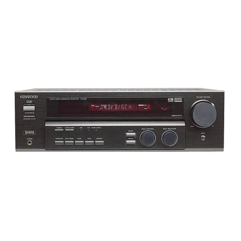
KENWOOD
AUDIO
VIDEO
SURROUND
RECEIVER
KR-300HT
INSTRUCTION
MANUAL
KENWOOD
CORPORATION
Model
availability
and
features
(functions)
may
differ
depending
on
country
and
sales
area.
J
98/12
111098765432197/12111098
2
Bef
or
e
applying
power
comes,
Gaution
:
Read
this
section
carefull
to
_
Units
are
designed
for
operation
as
follows.
U.S.A.
and
Canada
Australia
ensure
SES
.
AC120
V
only
Europe
and
U.K...
AC
240
V
only
China
and
Russia
AC
238
V
only
AC
220
V
only
*Other
countries
AC
110-120/220-240
¥
switchable
*AC
voltage
selection
AC
voltage
selector
switch
The
AC
voltage
selector
switch
on
the
rear
panel
is
set
to
the
voltage
aC
170-
AC
220-
that
prevails
in
the
area
to
which
the
unit
is
shipped.
Before
connecting
20
2aov~
the
power
cord
to
your
AC
outlet,
make
sure
that
the
setting
position
of
this
switch
matches
your
line
voltage.
If
not.
it
must
be
set
to
your
voltage
in
accordance
with
the
following
direction
Note:
Our
warranty
does
not
cover
damage
caused
by
excessive
line
voltage
due
to
improper
setting
of
the
AC
voltage
selector
switch
match
your
line
voltage
with
a
small
screwdriver
or
other
pointed
tool.
Safety
precautions
_.
fully
ensure
sat
WARNING:
TO
PREVENT
FIRE
OR
ELECTRIC
SHOCK,
DO
NOT
EXPOSE
THIS
APPLIANCE
TO
RAIN
OR
MOISTURE.
CAUTION:
TO
REDUCE
THE
RISK
OF
ELECTRIC
SHOCK,
DO
NOT
REMOVE
COVER
(OR
BACK).
NO
USER-SERVICEABLE
PARTS
INSIDE,
REFER
SERVICING
TO
QUALI-
FIED
SERVICE
PERSONNEL
CAUTION
RISK
OF
ELECTRIC
SHOCK
DO
NOT
OPEN
THE
LIGHTNING
FLASH
WITH
ARROWHEAD
SYMBOL,
WITHIN
AN
EQUILATERAL
TRIANGLE,
IS
IN-
TENDED
TO
ALERT
THE
USER
TO
THE
PRESENCE
OF
UNINSULATED
“DANGEROUS
VOLTAGE”
WITHIN
THE
PRODUCT'S
ENCLOSURE
THAT
MAY
BE
OF
SUFFICIENT
MAGNITUDE
TO
CONSTITUTE
A
RISK
OF
ELECTRIC
SHOCK
TO
PERSONS
THE
EXCLAMATION
POINT
WITHIN
AN
EQUILATERAL
TRIANGLE
IS
INTENDED
TO
ALERT
THE
USER
TO
THE
PRESENCE
OF
IMPORTANT
OPERATING
AND
MAINTENANCE
(SERVICING)
INSTRUCTIONS
IN
THE
LITERATURE
ACCOMPANYING
THE
APPLIANCE
j
if
your
unit
is
damaged
or
fails
to
operate,
notify
your
dealer
immediately.
If
your
unit
was
shipped
to
you
directly,
notify
the
shipping
company
without
delay.
Only
the
consignee
(the
person
or
company
receiving
the
unit)
can
file
a
claim
against
the
carrier
for
shipping
damage.
We
recommend
that
you
retain
the
original
carton
and
packing
materials
for
use
should
you
transport
or
ship
the
unit
in
the
future.
Unpack
the
unit
carefully
and
make
sure
that
all
accessories
are
put
aside
so
they
will
not
be
lost.
Examine
the
unit
for
any
possibility
of
shipping
damage
|
i
Accessories
FM
indoor
antenna
(1)
AM
loop
antenna
(1)
Loop
antenna
stand
(1}
Remote
contro!
unit
(1)
Batteries
(R6/AA)
(2)
KR-3OOHT
[En/K]}
Special
features
_.
DOLBY
PRO
LOGIC
&
DOLBY
3
STEREO
The
surround
system
reproduces
video
software
programs
carrying
the
[X\[samexeasn)
mark
with
similar
acoustic
effects
to
movie
theaters.
The
DOLBY
PRO
LOGIC
mode
controls
the
audia
signals
of
the
Front
Lef(/Right,
Center
and
Rear
surround channels
using
the
built-in
directivity
enhancer
circuit
te
reproduce
the
feeling
of
sound
motions
very
realistically.
The
DOLBY
3
STEREO
mode
can
reproduce
the
motions
of
sound
even
when
only
the
front
and
center
speakers
are
used,
by
providing
proper
acoustic
position
using
the
directivity
enhancer
circuit.
DSP
LOGIC
&
DSP
presence
The
DSP
LOGIC
mode
adds
presence
sound
components
obtained
from
the
DSP
(Digital
Signal
Processor)
to
the
signals
output
from
the
DOLBY
PRO
LOGIC
(Left,
Center,
Right
and
Surround
channels),
allowing
movie
software
programs
to
be
played
with
a
similar
feeling
of
Presence
to
movie
theaters
in
a
listening
reom
in
home.
The
DSP
presence
mode
adds
presence
sound
components
obtained
from
the
DSP
to
the
original
source
signals,
allowing
music
source
entertainment
with
the
feeling
of
presence
in
an
arena,
stadium
or
jazz
club
in
a
listening
room
at
home.
SRS
3D
Stereo
The
SRS
(Sound
Retrieval
System)
is
an
innovative
system
simulating
a
3-dimensional
sound
space,
which
features
clearly
improved
feelings
of
depth,
sound
field
extension
and
acoustic
image
positioning
as
well
as
a
widened
listening
area.
to
ensure
safe
operation.
SEee
Contents
ution
:
Read
the
pages
marked
AN
carefully
Before
applying
POWER
o....s.ssecssessssssssssssecsseessseesssesssssssnsnssesssssssssssssssesnsnscenanseens
2
A\
Before
applying
power
2
ay
Safety
precautions
2
Special
features
0...
3
SYSlOMI
CORMECTON
..sesccsccoseeessscerssscessssseneesecesesnsstsinsasssecsenssssesssstuennssssssseneasinnneessseressensaressenitaee
4
4
About
the
system
control
connections
.
5
Connections.of
SPCAKEFS
00...
6
Connections
of
ANt@NN
oo...
7
FM
DE-EMPHASIS/CHANNEL
SPACE
SWITCH
......cc.ccccccccssesecscescssessesetsssreevessearessistisasessisesteeeeeeeeecs
8
Controls
and
indicators
$
Operation
of
remote
Control
UMit....ecccecsecossusssesssissssssenssssrasesssesscesssineeissvissssssneesisiseeeiees
10
Playing
music
12
Sound
adjustment
functions
Recording
16
Broadcast
Reception
17
Receiving
broadcast
stations
17
Receiving
radio
stations
by
specifying
its
frequenc
18
Storing
radio
stations
in
memory
(Station
preset)
Receiving
a
preset
station
Receiving
all
preset
stations
in
order
(PCALL}.
Operation
of
video
components
Playback
of
videotape
a
Recording
af
video
source
(VIDEO2
/AV
AUX
>
VIDEO?)
.
Presence
play
Adjustments
for
surround
play
Surround
Play
occ
Adjusting
the
surrouhd
effects
(DSP
presence
and
DSP
LOGIC
modes
only)
SRS
3D
Stereo
(Sound
Retrieval
System}
in
case
of
difficulty
A\
Specifications
....
Make
connection
as
shown
below.
When
connecting
the
related
system
components,
refer
also
to
the
instruction
manuals
of
the
related
components.
4
Do
not
plug
in
the
power
lead
until
all
connections
are
completed.
Malfunction
of
microcomputer
Ef
operation
is
not
possible
or
erroneous
display
appears
even
though
ali
connections
have
been
made
properly,
reset
the
micro-
computer
referring
to
“In
case
of
difficulty”.
-2e.
Video
deck
1,
cassette
deck
1
OuT
or
MD
recorder
7
cr
Sil
Auto
[S}
—
soe
(Xe)
===)
S|
f
1
*
IN
System
'
Video
deck
2
or
DVD/LD
control
cord
*1
The
system
control
cord
can
player
be
connected
when
a
Audio
OUT
:
Q
a)
QO
Teo
ooce
06
KENWOOD
audio
compo-
nent
system
is
connected.
OUT
*2
Cassette
deck
2
2
|
SSS
REC
|
PLAY
iN
OUT
vy
,
? ?
ce
an
i
Video
Shape
of
AC
outlets
U.S.A,
CANADA
and
China
Australia
Other
countries
5
5a
To
wall
AC
outlet
Video
IN
System
control
cord
Multiple
CD
player
Turntable
Video
OUT
Audio
Video
deck
3
or
video
camera
=|
OUT
5
ool
==
Ly
*2
Do
not
connect
system
control
cord
to
the
cassette
deck
connected
to
the
TAPE
2
MONITOR
jacks.
Caution
regarding
placement
(Except
for
U.S.A.
and
Canada}
To
maintain
proper
ventilation,
be
sure
to
leave
a
space
around
the
unit
(from
the
largest
outer
dimensions
including
projections)
equal
to,
or
greater
than,
shown
below.
Left
and
right
panels
:
10cm
Rear
panel
1:
10cm
Top
panel
:
50cm
KR-3OGHT
[En/K}
About
the
system
control
connections
Se
een
Se
Connecting
system
control
cords
after
connecting
a
KENWOOD
audio
component
system
lets
you
take
advantage
of
convenient
system
control
operations.
There
are
two
KENWOOD
system
control
modes.
Make
connections
according
to
the
groups
of
terminal
symbols
shown
beiow.
(X88:
mode:
lets
you
combine
(XU), (XSi,
and
XS8i
terminals
SSLIB)
Mode:
for
GLIB)
terminats
only
This
unit
is
compatibie
with
both
[XS8]
and
[SL16]
modes.
It
comes
from
the
factory
set
to
the
[SL16]
mode.
To
switch
to
the
[XS8]
mode,
follow
the
instructions
in
“SWITCHING
BETWEEN
[XS8]
AND
[SL16]”
below.
EXAMPLE:
{XS8]
mode
connections
EXAMPLE:
[SL16}
mode
connections
The
underlined
portion
represents
the
setting
of
the
system
The
underlined
portion
represents
the
setting
of
the
system
control
mode.
control
mode.
[tumave
|
Turntable
[SL16]
(XS8]
[SL16]
(XS8)
System
System
[SL16}
control
(SL16]
MD
Recorder
control
cord
cord
Multiple Muttipte
CD
Player
CD
Player
e@Some
CD
players
and
cassette
decks
are
not
compatible
with
the
[SL16]
systern
control
mode.
Be
sure
to
use
the
[XS8]
system
control
mode
when
making
system
connections
with
equipment
that
1s
not
(SL16]
compatible
@Some
MD
players
ave
not
system
control
compatible.
You
cannot
make
system
control
connections
to
this
kind
of
equipment.
[$L16]
[XS]
[X$8]
[XR]
{SL16]
[XS]
(XS8)
[XR]
[SL16]
[XS]
[X$8]
[SL16]
[XS]
[XS8]
equipment
consists
of
this
kind
of
combination,
please
do
not
connect
any
system
control
cords.
Even
without
system
control
cords,
normal
operations
can
be
carried
out
without
affecting
performance
2.
Donot
connect
system
control
cords
to
any
components
other
than
those
specified
by
KENWOOD.
It
may
cause
a
malfunction
and
damage
your
equipment
3.
Be
sure
the
system
control
plugs
are
inserted
all
the
way
In
to
the
system
control
terminals
1.
[SL16]
equipment
cannot
be
combined
with
[XB],
[XS],
and
[XS8]
equipment
for
system
operations.
If
your
Mores}
ABOUT
THE
SYSTEM
CONTROL
OPERATIONS
SWITCHING
BETWEEN
[XS8]
AND
[SL16]
Remote
Control
(possible
when
the
system
control
mode
The
system
control
mode
can
be
switched
over
easily
with
the
|
matches)
following
operation.
Lets
you
operate
source
components
with
the
system
remote
@
Unplug
the
AC
power
cord
from
the
wall
outlet
supplied
with
this
unit.
@
Set
the
SYSTEM
CONTROL
switch
on
the
rear
panel
to
the
desired
Position
Automatic
Operation
(Except
[XR]
equipment}
When
you
start
playback
from
a
source
component,
the
input
selector
on
this
unit
switches
to
that
component
automatically.
Note
{Except
TAPE
2)
Synchronized
Recording
(Except
(XR]
equipment)
Lets
you
synchronize
recording
with
the
start
of
playback
when
recording
from
CD
or
MD.
}
@
This
operation
does
not
affect
the
items
stored
in
memory.
Connect
all
cords
firmly.
If
connections
are
loose,
there
could
be
loss
of
sound
or
noise
produced
=|
2
When
piugging
and
unplugging
connection
cords.
be
sure
to
first
remove
the
power
cord
from
the
AC
outlet.
Plugging
/
unplugging
connection
as
cords
without
removal
of
the
power
cord
can
cause
malfunctions
or
damage
to
the
unit
3.
Do
not
connect
up
a
power
source
whicn
is
larger
than
that
indicated
on
the
socket
at
the
rear
of
the
unit
4
Ifthe
system
contrat
cords
or
audio
cards
are
not
connected
properly,
the
remote
control
or
automatic
operation
between
system
components
wiil
not
work
properly

Other manuals for KR-300HT

3

Other Kenwood Stereo Receiver manuals

Kenwood 1090VR User manual

Kenwood

Kenwood 1090VR User manual

Kenwood KR-200HT User manual

Kenwood

Kenwood KR-200HT User manual

Kenwood KR-A57R User manual

Kenwood

Kenwood KR-A57R User manual

Kenwood KR-A5520 User manual

Kenwood

Kenwood KR-A5520 User manual

Kenwood KR-V999D User manual

Kenwood

Kenwood KR-V999D User manual

Kenwood KRF-V7060D User manual

Kenwood

Kenwood KRF-V7060D User manual

Kenwood KRX-593 User manual

Kenwood

Kenwood KRX-593 User manual

Kenwood KR-795 User manual

Kenwood

Kenwood KR-795 User manual

Kenwood KRF-V5020 User manual

Kenwood

Kenwood KRF-V5020 User manual

Kenwood KR-V7060 User manual

Kenwood

Kenwood KR-V7060 User manual

Kenwood KR-V9020 User manual

Kenwood

Kenwood KR-V9020 User manual

Kenwood KR-A4040 User manual

Kenwood

Kenwood KR-A4040 User manual

Kenwood KR-V6050 User manual

Kenwood

Kenwood KR-V6050 User manual

Kenwood KR-V8040 User manual

Kenwood

Kenwood KR-V8040 User manual

Kenwood VR9070 - THX-Certified Home Theater Receiver User manual

Kenwood

Kenwood VR9070 - THX-Certified Home Theater Receiver User manual

Kenwood KR-6170 User manual

Kenwood

Kenwood KR-6170 User manual

Kenwood KRF-X9992D User manual

Kenwood

Kenwood KRF-X9992D User manual

Kenwood VRS-6100 User manual

Kenwood

Kenwood VRS-6100 User manual

Kenwood KRF-X9070D User manual

Kenwood

Kenwood KRF-X9070D User manual

Kenwood VRS-6200 User manual

Kenwood

Kenwood VRS-6200 User manual

Kenwood KRF-X9090D User manual

Kenwood

Kenwood KRF-X9090D User manual

Kenwood KRF-V5050D User manual

Kenwood

Kenwood KRF-V5050D User manual

Kenwood KRC-754 D User manual

Kenwood

Kenwood KRC-754 D User manual

Kenwood 104AR User manual

Kenwood

Kenwood 104AR User manual

Popular Stereo Receiver manuals by other brands

Teac AG-680 Service manual

Teac

Teac AG-680 Service manual

Teac AGV1050 owner's manual

Teac

Teac AGV1050 owner's manual

Sony STR-435 operating instructions

Sony

Sony STR-435 operating instructions

Pioneer Elite SC-68 Service manual

Pioneer

Pioneer Elite SC-68 Service manual

Pioneer SX-1250 operating instructions

Pioneer

Pioneer SX-1250 operating instructions

Marantz CINEMA 70S owner's manual

Marantz

Marantz CINEMA 70S owner's manual

Yamaha RX-830 owner's manual

Yamaha

Yamaha RX-830 owner's manual

Pioneer AVH-Z7250BT owner's manual

Pioneer

Pioneer AVH-Z7250BT owner's manual

Denon AVR-1311 owner's manual

Denon

Denon AVR-1311 owner's manual

Denon AVR-S760H owner's manual

Denon

Denon AVR-S760H owner's manual

Denon AVR-X7200W Service manual

Denon

Denon AVR-X7200W Service manual

Sony XAV-1500 operating instructions

Sony

Sony XAV-1500 operating instructions

Radio Shack DX-399 owner's manual

Radio Shack

Radio Shack DX-399 owner's manual

Sony STR-DE535 - Fm Stereo/fm-am Receiver operating instructions

Sony

Sony STR-DE535 - Fm Stereo/fm-am Receiver operating instructions

Pioneer SX-1000TA operating instructions

Pioneer

Pioneer SX-1000TA operating instructions

Yamaha MusicCast TSR-5B3D owner's manual

Yamaha

Yamaha MusicCast TSR-5B3D owner's manual

Sony STR-DG500 - Multi Channel Av Receiver Service manual

Sony

Sony STR-DG500 - Multi Channel Av Receiver Service manual

Sherwood Newcastle RX-770 operating instructions

Sherwood

Sherwood Newcastle RX-770 operating instructions

manuals.online logo
manuals.online logoBrands
  • About & Mission
  • Contact us
  • Privacy Policy
  • Terms and Conditions

Copyright 2025 Manuals.Online. All Rights Reserved.