Introduction
Your
choice
of
this
product
indicates
that
you
are
a
devotee
to
excellence
in
sound
reproduction.
We
appreciate
your
patronage
and
take
pride
in
the
long
tradition
of
quality
components,
that
our
company
repre-
sents.
So
that
you
can
get
the
most
out
of
your
unit,
we
suggest
that
you
take
the
time
to
read
through
this
manual
before
you
hook
up
and
operate
your
system.
This
will
acquaint
you
with
operating
features,
and
system-connection
con-
siderations,
so
that
your
listening
pleasure
will
be
en-
hanced
right
from
the
start.
You
will
notice
that
in
all
aspects
of
planning,
engineering,
styling,
Operating
con-
venience
and
adaptability,
we
have
sought
to
anticipate
your
needs
and
desires.
Keep
this
manual
handy
for
future
reference.
For
your
records
Record
the
serial
number,
found
on
the
back
of
the
unit,
in
the
spaces
designated
on
the
warranty
card,
and
in
the
space
provided
below.
Refer
to
the
model
and
serial
numbers
whenever
you
call
upon
your
dealer
for
informa-
tion
or
service
on
this
product.
Model
Serial
Number
Unpacking
Unpack
the
unit
carefully
and
make
sure
that
all
accesso-
ries
are
put
aside
so
they
will
not
be
lost.
Examine
the
unit
for
any
possibility
of
shipping
damage.
If
your
unit
is
damaged
or
fails
to
operate,
notify
your
dealer
immediately.
If
your
unit
was
shipped
to
you
directly,
notify
the
shipping
company
without
delay.
Only
the
consignee
(the
person
or
company
receiving
the
unit)
can
file
a
claim
against
the
carrier
for
shipping
damage.
We
recommend
that
you
retain
the
original
carton
and
packing
materials
for
use
should
you
transport
or
ship
the
unit
in
the
future.
For
the
U.S.A.
Note
to
CATV
system
installer:
This
reminder
is
provided
to
call
the
CATV
system
installer’s
attention
to
Article
820-40
of
the
NEC
that
provides
guidelines
for
proper
grounding
and.
in
par-
ticular,
specifies
that
the
cable
ground
shall
be
con-
nected
to
the
grounding
system
of
the
building,
as
close
to
the
point
of
cable
entry
as
practical.
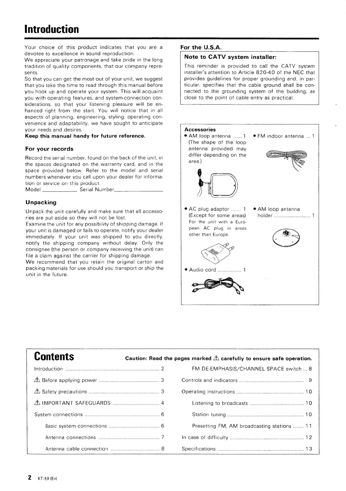
Accessories
@
AM
loop
antenna
......
1
©@FM
indoor
antenna
...
1
(The
shape
of
the
loop
antenna
provided
may
differ
depending
on
the
area.)
®
AC
plug
adaptor
........
1
@AM
loop
antenna
(Except
for
some
areas)
|AL6)
(0
(=|
querer
np
irere
rere
1
For
the
unit
with
a
Euro-
pean
AC
plug
in
areas
other
than
Europe.
gy
@
Audio
cord
Contents
INTCODUCTION
-
tosis
cildverecgbastebsstasertnlin
nets
ctsee
eateanty
teeta
2
A\
Before
APPIYING
POWET
ooo.
ee
eee
enecetecceeeceeeereeeeee
3
AN
Safety
precautions
o....cccceccccseccsesssecsessessestesseesessees
3
ZX
IMPORTANT
SAFEGUARDS
00.0.0.
ccc
4
SYStEM
CONNECTIONS:
siversscnten
Mid
sa
ieseaatdasbelAvees
6
BaSic
SYSTEM
CONNECTIONS
occ
eeeeceeeteeeteeees
6
ANteNna
CONNECTIONS
oo...
eee
cece
cece
teeceeteereeeeees
7
|
Antenna
cable
connection...
ccc
8
2
kT-59
(En)
Caution:
Read
the
pages
marked
A\
carefully
to
ensure
safe
operation.
FM
DE-EMPHASIS/CHANNEL
SPACE
switch
....8
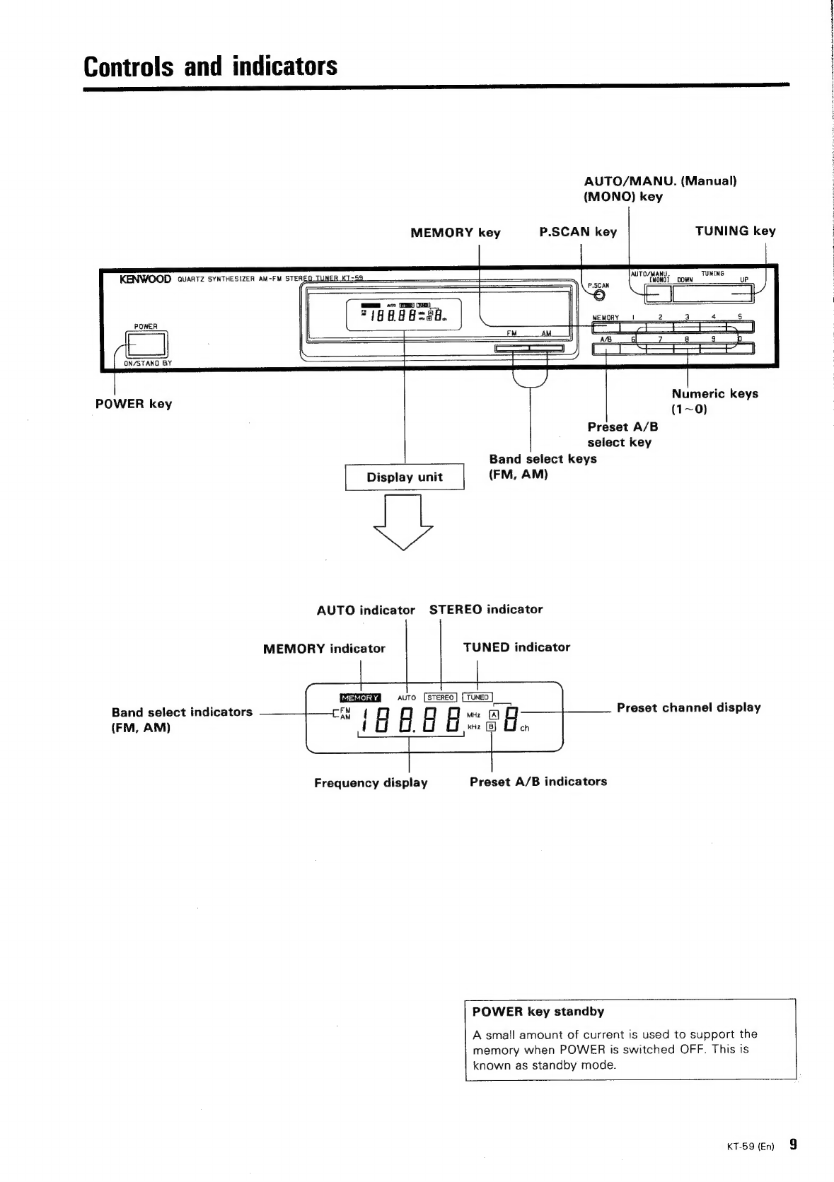
Controls
and
indicators
.......c
ce
cceeeeeeeeceeeeeeeeeteesenes
9
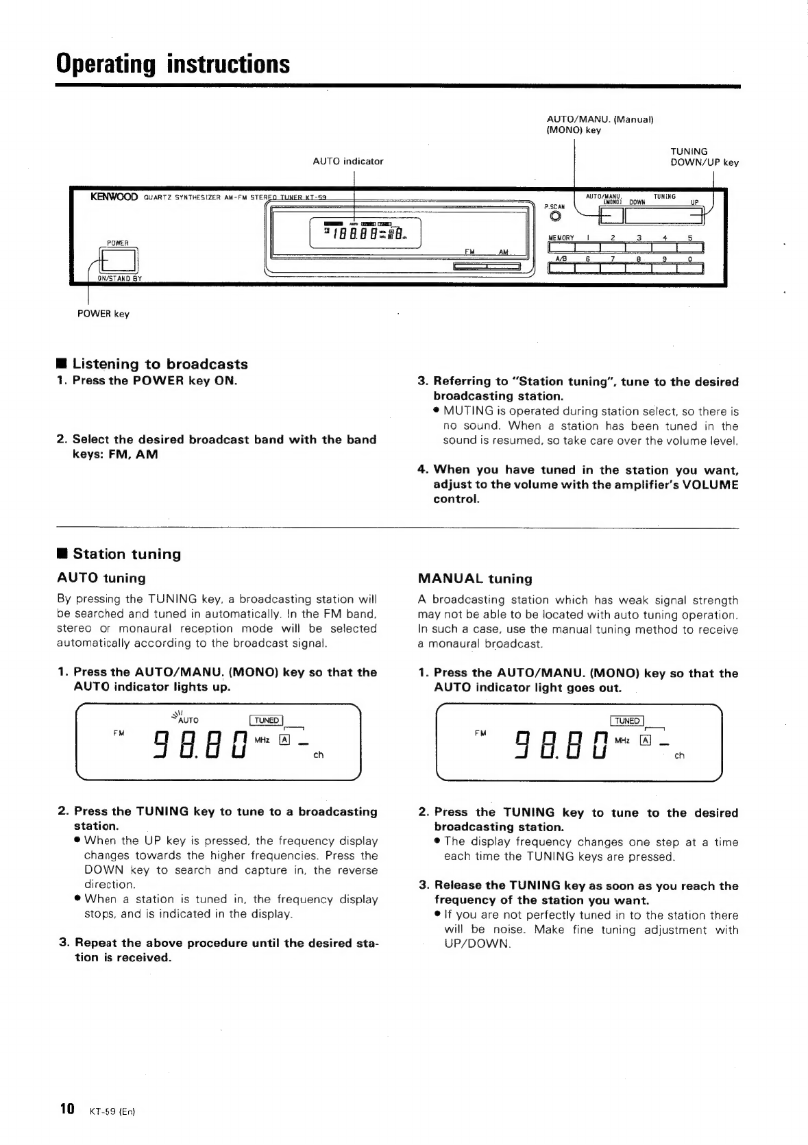
Operating
iINStrUCtIONS
oo...
ee
eect
ee
eeeeeeteeteeteetteeees
10
Listening::to’
broadcasts’.
23:
cette
eituhdehenits
10
Station
tuUNING
.cccecihes
i
nese
antes
10
Presetting
FM,
AM
broadcasting
stations
........
11
In
Case-of
difficulty
3,2:
tai
ie
Ai
ee
12
SPECIFICATONS*
ncn
ee
ee
ea
cee
ed
13