CG Products XR1-E User manual

XR1-E
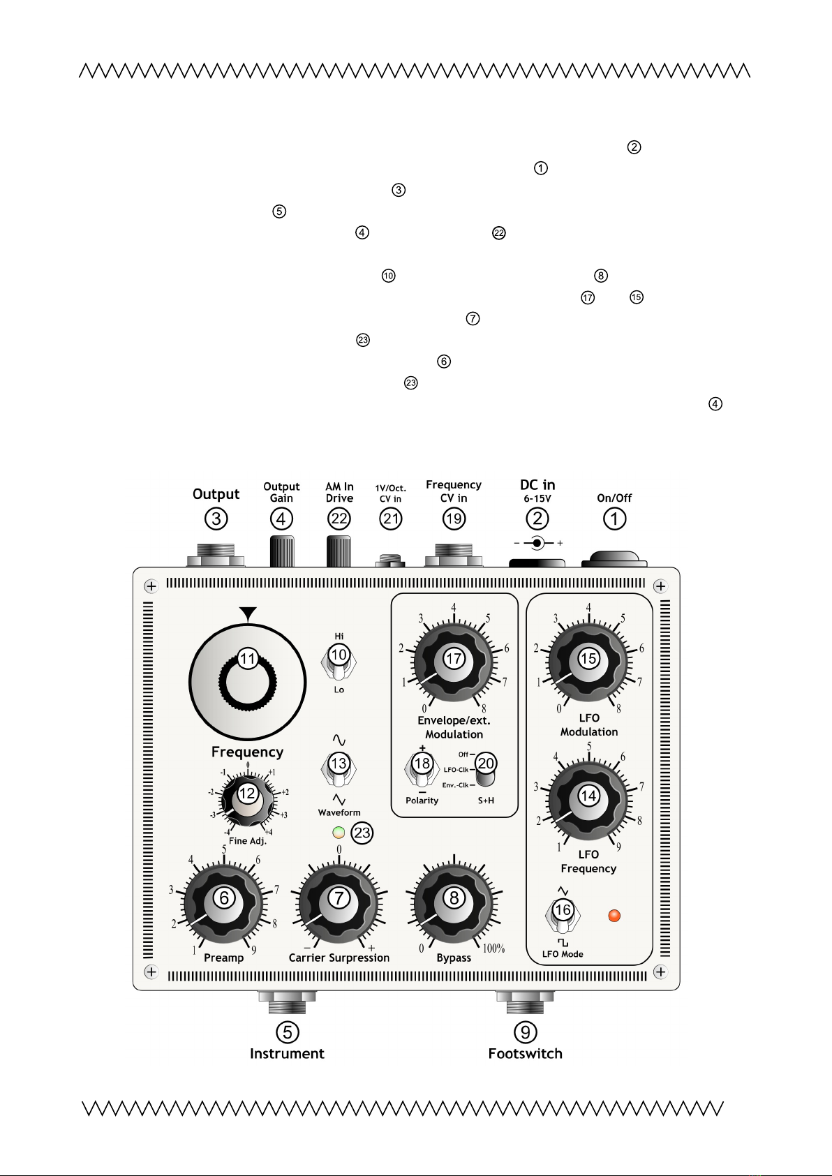
Ring Modulation Oscillator
The
XR1-E
is an analog ring modulator with internal oscillator, preamp and LFO in a nice hand-
made casing.
Offering a wide ariety of control options, it may be used to generate sounds from the typical
ring modulation and tremolo-like wa eforms to glissando and random-like patterns or distortion.
An integrated low-noise preamp (with much headroom) is allowing to adapt many kinds of input
sources such as microphones, e-guitars or electronic instruments.
Optical o er iew of the oscillator’s and preamp's o erdri e beha iour pro ides a bicolor LED.
The frequency is manually adjustable by knobs for coarse and fine tuning and a switch for high or low (tremolo) range. An
en elope follower, a LFO and a Sample+Hold may be used for frequency modulation. The en elope CV can be optionally
replaced by an external signal or a oltage from a foot pedal, appliable on a jack on the rear. Further, a minijack 1V/oct.
input is a ailable for controlling the
XR1-E
’s frequency by an external CV.
The
XR1-E
has a footswitch input on its front to apply an external footswitch (not included) for switching between the
effect and the original (true bypass)
.
The output le el of the processed signal can be aligned by a knob on the rear.
Due to the ability of battery operation the de ice is independent from external power supply, but there is a socket for a
DC adaptor too (DC adaptor not included).
The
XR1-E
is based on a function generator chip, which warm and smooth sound makes it excellently suitable for ring
modulation and electronic music.
Low noise preamp
Bicolor LED for isual control
Frequency modulation with en elope follower, LFO and/or Sample+Hold
1V/oct minijack input and 2nd input for external frequency control
Footswitch input – true bypass
Output gain adjustable
Battery (6x AA) or with external DC supply
Unique handmade casing
1
Quick start guide
1. Insert batteries or accus (6x AA Mignon) or connect a power adaptor (DC 9-16V,
+pole: the outer side of the plug). Set the power switch upwards to "On". Connect an
amplifier, mixer etc. to the Output and connect an instrument or microphone to the
Instrument input .
2. Turn the knobs 'Output Gain' and 'AM in Dri e'
23456789
21
10 11 13 14 15 16 17 18 19
20 22
12
Objekt in Pfade:
4
4
14
Falsche Zahlen
4
on the backside in ≈middle
position.
3. Set the frequency selector switch on "Hi". Turn the Bypass pot in fully right
position : "100%" and the en elope and LFO modulation knobs and in fully left
position: "0". Mo e knob 'Carrier Surpression' in middle position = "0" on the scale/
denter locked; watch the LED
2 3 456789
21
10 11 13 14 15 16 17 18 19
20 22
12
Objekt in Pfade:
4
4
14
Falsche Zahlen
48
9
10
11
12
23
for indication).
Adjust the "Preamp" input gain controller while playing your instrument and listen
for optimal performance. Watch LED
2 3 456789
21
10 11 13 14 15 16 17 18 19
20 22
12
Objekt in Pfade:
4
4
14
Falsche Zahlen
48
9
10
11
12
23
- it should e en not light red.
4. When using an external footswitch for dry/wet control, adjust 'Output Gain' knob (on
the back) for same output amplitude of the effect and the original signal.
2
Functions
On/Off Switch
Switches the power supply on or off.
Note: In combination with an external power adaptor only the XR1-E will be switched off and
not
the power adaptor itself.
External Power Supply Input
For operation of the
XR1-E
with an external DC power adaptor. The connection is a standard DC
plug with 2.1mm diameter hole. The "+"pole is the outer contact, which is almost common for
effect pedals etc.. The internal batteries will be switched off when this socket is in use. The input
oltage range is 6V–15V. Typical current dissipation at 9V: ≈ 140mA.
Output
For connecting the
XR1-E
to an amplifier, mixer or another following stage.
The output le el is adjustable by the knob 'Output Gain' on the rear.
Maximum output oltage is ≈ 8Vpp (Knobs and 'AM In Dri e'
2 3 456789
21
10 11 13 14 15 16 17 18 19
20 22
12
Objekt in Pfade:
4
4
14
Falsche Zahlen
4
fully turned up)
When using a footswitch applied on and the oscillator is shut off (or if the
XR1-E
is switched
off), the output pro ides directly the original signal applied on instrument input ('
true bypass
' –
the signal it is not flowing through any electronic circuit when bypassed)
Output Gain
(on the back) controls the final output amplitude pro ided on Output . When using an external
footswitch inserted to ('Footswitch'), this knob allows to align the effect signal to the dry input
signal. Further, it may be useful to add some extra amplification if needed.
Instrument Input
Input jack for instrument or microphone. Max. input oltage without distortion: ≤8Vpp; impedance:
ca. 600kΩ.
Preamp Gain Control
Input le el control for the instrument input’s preamp, which is sourcing the oscillator's
amplitude modulation input. The preamp is able to process larger input le els (such as coming
from electronic instruments), as well as smaller ones (such as coming from dynamic microphones).
The bicolor LED
2 3 456789
21
10 11 13 14 15 16 17 18 19
20 22
12
Objekt in Pfade:
4
4
14
Falsche Zahlen
48
9
10
11
12
23
signalizes - if lighting red - when the preamp is becoming o erdri en. For best
signal-to-noise ratio the le el should be e en below the point when the LED is lighting red. The
preamp shows soft clipping beha iour.
Carrier Surpression Control
For ‘standard’ operation, this knob is in its middle position (denter locked, '0' on scale). When
turning it cw or ccw, the oscillator's tone will appear. This may be used for special sound effects;
furthermore when using a ery low frequency input signal (such as e.g. pulse patterns), the
adjusting may influence the sound beha iour.
3
23456789
21
10 11
12
13 14 15 16 17 18 19
20 22
12
Objekt in Pfade:
23456789
21
10 11
12
13 14 15 16 17 18 19
20 22
12
Objekt in Pfade:
23456789
21
10 11
12
13 14 15 16 17 18 19
20 22
12
Objekt in Pfade:
23456789
21
10 11
12
13 14 15 16 17 18 19
20 22
12
Objekt in Pfade:
4
23456789
21
10 11
12
13 14 15 16 17 18 19
20 22
12
Objekt in Pfade:
4
23456789
21
10 11
12
13 14 15 16 17 18 19
20 22
12
Objekt in Pfade:
4
23456789
21
10 11
12
13 14 15 16 17 18 19
20 22
12
Objekt in Pfade:
4
Note:
There will always remain a little bit of the oscillator sound (2nd harmonics etc.). For best
performance, make sure that the input signal le el is high.
Bypass
This 'dry/wet' control knob is changing the ratio between input signal (preamplified) and the ring
modulated effect signal. Turning the knob fully left will pro ide only the preamplified input signal;
by turning the knob clockwise the effect will be mixed with original. Fully right position = "100%":
the pure ring modulation effect signal.
Footswitch Input
An external 2pole footswitch (not included) can be applied.
•Switch closed: The dry original input signal (
true bypass
)
•Switch opened: The effect signal (also depending on postion of the "Bypass" control knob )
The switching is also controllable by an external logic signal (0V = effect , +5V = dry), e.g. a gate
signal from a synthesizer.
To align the output amplitudes of the dry and wet signal, adjust the output signal with 'Output
Gain' knob (on the back) .
Oscillator Frequency High/Low Switch
Hi: ≈ 15Hz – 20000 Hz (Audio range)
Lo: ≈ 0,3Hz – 400 Hz (Tremolo/Bass)
(without modulation and/or CV)
In "Hi" position, the oscillator is mainly working in audio range. The amplitude modulation will
generate additional audio frequencies – sum and difference tones of the input signal and the
oscillator frequency.
In "Lo" position, the oscillator is working with subaudio and bass frequencies. The amplitude
modulation result is a tremolo-like sound. Volume of the input signal will change constantly with
the oscillator frequency.
Oscillator Frequency Control
Coarse adjustment of the amplitude modulation (AM) oscillator frequency.
Oscillator Frequency Fine Adjustment Control
Fine tuning of the oscillation frequency. Range is about 4 – 5 semitones (quarte).
Oscillator Wa eform Switch
The ring modulator oscillator wa eform can be selected between sinewa e and triangle. In " "
(sine) position, the effect is a more smooth sound with less o ertones; in " " (triangle) mode the
generated sounds are rougher and with more o ertones. Knob 'AM In Dri e'
2 3 456789
21
10 11 13 14 15 16 17 18 19
20 22
12
Objekt in Pfade:
4
4
14
Falsche Zahlen
4
(on the rear) also
affects the beha iour of these modulations.
LFO Frequency Control
Speed control of the internal LFO (low frequency oscillator) for frequency modulation of the ring
modulation oscillator. Frequency is from ≈0.06Hz (left position ) to ≈ 44Hz (right position)
4
23456789
21
10 11
12
13 14 15 16 17 18 19
20 22
12
Objekt in Pfade:
4
23456789
21
10 11
12
13 14 15 16 17 18 19
20 22
12
Objekt in Pfade:
4
23456789
21
10 11
12
13 14 15 16 17 18 19
20 22
12
Objekt in Pfade:
4
23456789
21
10 11
12
13 14 15 16 17 18 19
20 22
12
Objekt in Pfade:
4
23456789
21
10 11
12
13 14 15 16 17 18 19
20 22
12
Objekt in Pfade:
4
23456789
21
10 11
12
13 14 15 16 17 18 19
20 22
12
Objekt in Pfade:
4
2 3 456789
21
10 11
12
13 14 15 16 17 18 19
20 22
12
Objekt in Pfade:
4
The LFO frequency is also displayed by the orange LED for isual control.
LFO Modulation Depth Control
Adjusts the LFO’s frequency modulation depth.
LFO Wa eform Switch
The LFO wa eform is selectable between triangle (" ") and squarewa e (" "). " " pro ides a
continously up-and down gliding pitch, while " " makes the oscillator shifting between two
tones.
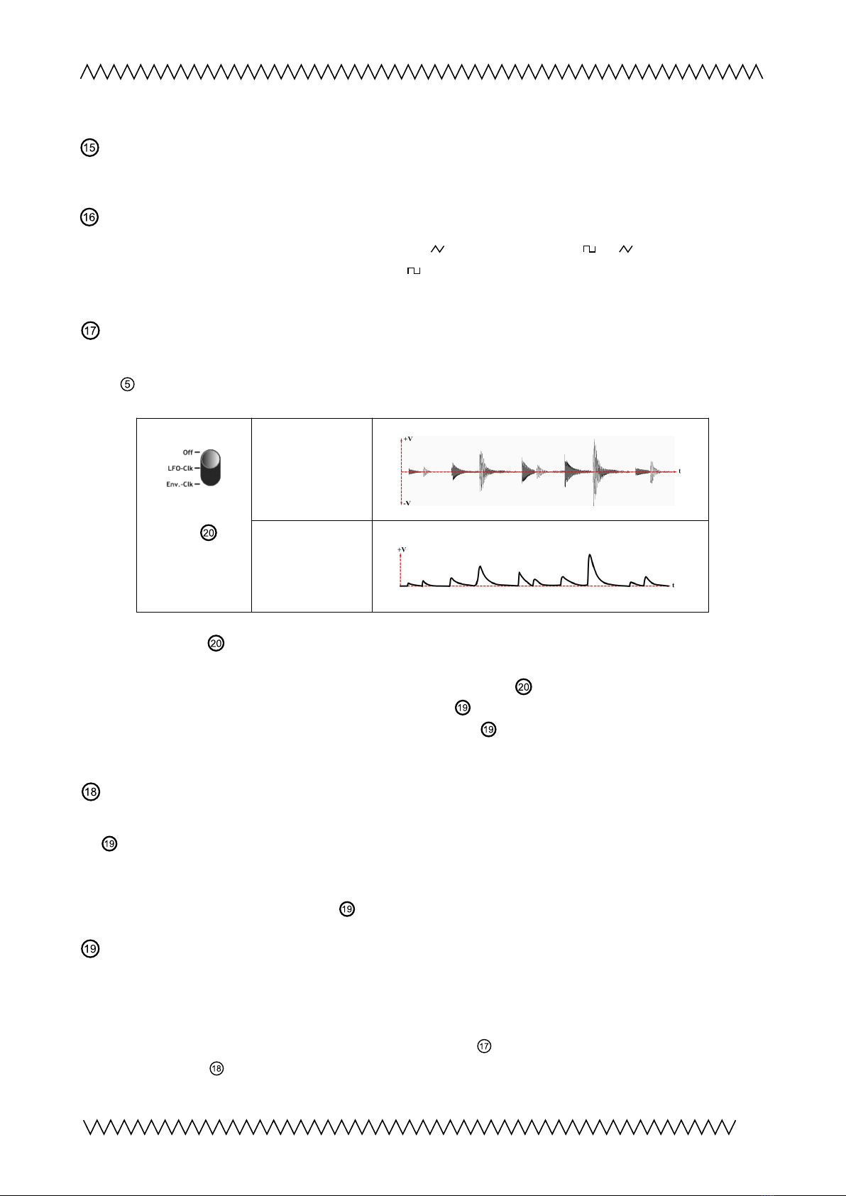
En elope Follower / Sample+Hold / ext. CV Modulation Depth Control
The internal en elope follower con erts the olume le el of the audio signal on the instrument
input into a control oltage, which can be used for modulating the oscillator frequency.
Switch
S+H'
in upper
position
The preamplified
audio signal
The generated
en elope signal for
frequency
modulation
With switch 'S+H' in upper position, the amount of the en elope modulation is adjustable by
this knob ( Or alternati ely, the amount of Sample+Hold modulation can be adjusted, depending
on the position of switch 'S+H'; please read the referring point ).
If the external frequency CV (= Control Voltage) input is used, the internal en elope follower
will be switched off and replaced by the signal applied on - e.g. from a pedal (or the respecti e
S+H modulation).
En elope Follower / Sample+Hold / ext. CV Modulation In ersion Switch
Switches the modulation polarity (from the en elope follower, Sample+Hold or an external source
on ) from positi e to negati e. If the switch is in upper position, the pitch of the AM oscillator
will increase with higher oltage of the modulation signal. With the switch in lower position 'In '
(="In ersion") the pitch will decrease with higher input oltage. The in ersion switch works also for
a control oltage signal connected to .
External Frequency Control Input
Allows to control the oscillator pitch by an external control oltage (CV) or an external resistor. By
connecting a jack to this input, the internal en elope follower/S+H will be shut off and instead the
applied control oltage will modulate the oscillator's frequency (with switch 'S+H' in upper
position); the modulation depth can be adjusted by knob ; the modulation CV's polarity can be
in erted by switch .
5
23456789
21
10 11
12
13 14 15 16 17 18 19
20 22
12
Objekt in Pfade:
4
23456789
21
10 11
12
13 14 15 16 17 18 19
20 22
12
Objekt in Pfade:
4
23456789
21
10 11
12
13 14 15 16 17 18 19
20 22
12
Objekt in Pfade:
4
23456789
21
10 11 13 14 15 16 17 18 19
20 22
12
Objekt in Pfade:
4
4
14
Falsche Zahlen
4
23456789
21
10 11 13 14 15 16 17 18 19
20 22
12
Objekt in Pfade:
4
4
14
Falsche Zahlen
4

Further, a +5V DC oltage ( ia 10kΩ resistor) is pro ided on , a ailable on the middle connector
of a 3pole jack plugged in . Thus may be useful, for example, in combination with a sensor or a
pedal. In the latter case, a common passi e foot pedal (e.g. the Moog ‚EP-3‘) with 3pole jack
should work.
When using the Sample+Hold (switch 'S+H'
in middle or lower position), the external
signal will replace the en elope follower's
oltage and this external signal in
combination with the LFO will be processed
by the Sample+Hold (please read the
referring point ).
S+H Sample+Hold switch
Alternati ely to the modulation with the en elope shape (with switch in upper position 'off'), a
Sample+Hold circuit can be acti ated for frequency modulation (switch in middle or lower
position).
A Sample+Hold is ha ing two inputs, an analog oltage input and a clock input, and an output
pro iding the generated Sample+Hold oltage. Each time when the clock signal is acti ating the
S+H, the S+H is reading the momentary oltage from its analog input and holds it until the next
clock impulse is coming. The results are staircase- or glissando-like sound patterns, if the S+H is
used for frequency modulation. The XR1-E's Sample+Hold is using the internal LFO and the
en elope follower (with a threshold function) for sourcing the S+H inputs. The switch 'S+H'
determines if the S+H is acti e, and whether the LFO is pro iding the clock signal and the
en elope shape is the analog input of the S+H, or ice ersa.
•
Upper position
Off: The S+H function is switched off, for en elope modulation.
•
Middle position
LFO-Clk: The squarewa e signal of the LFO is the clock of the S+H and the
en elope shape is its analog input.
•
Lower position
En .-Clk: The en elope shape con erted to a trigger signal (from a certain
le el of the en elope shape) is the S+H's clock and the trianglewa e of the LFO is going to
its analog input.
When using the external frequency control input , the en elope follower’s signal will be replaced
by that.
Switch
'S+H'
in middle position
The LFO's squarewa e
output is the S+H's clock
signal
The en elope shape is the
S+H's analog input
The resulting frequency
modulation oltage
6
23456789
21
10 11 13 14 15 16 17 18 19
20 22
12
Objekt in Pfade:
4
4
14
Falsche Zahlen
4
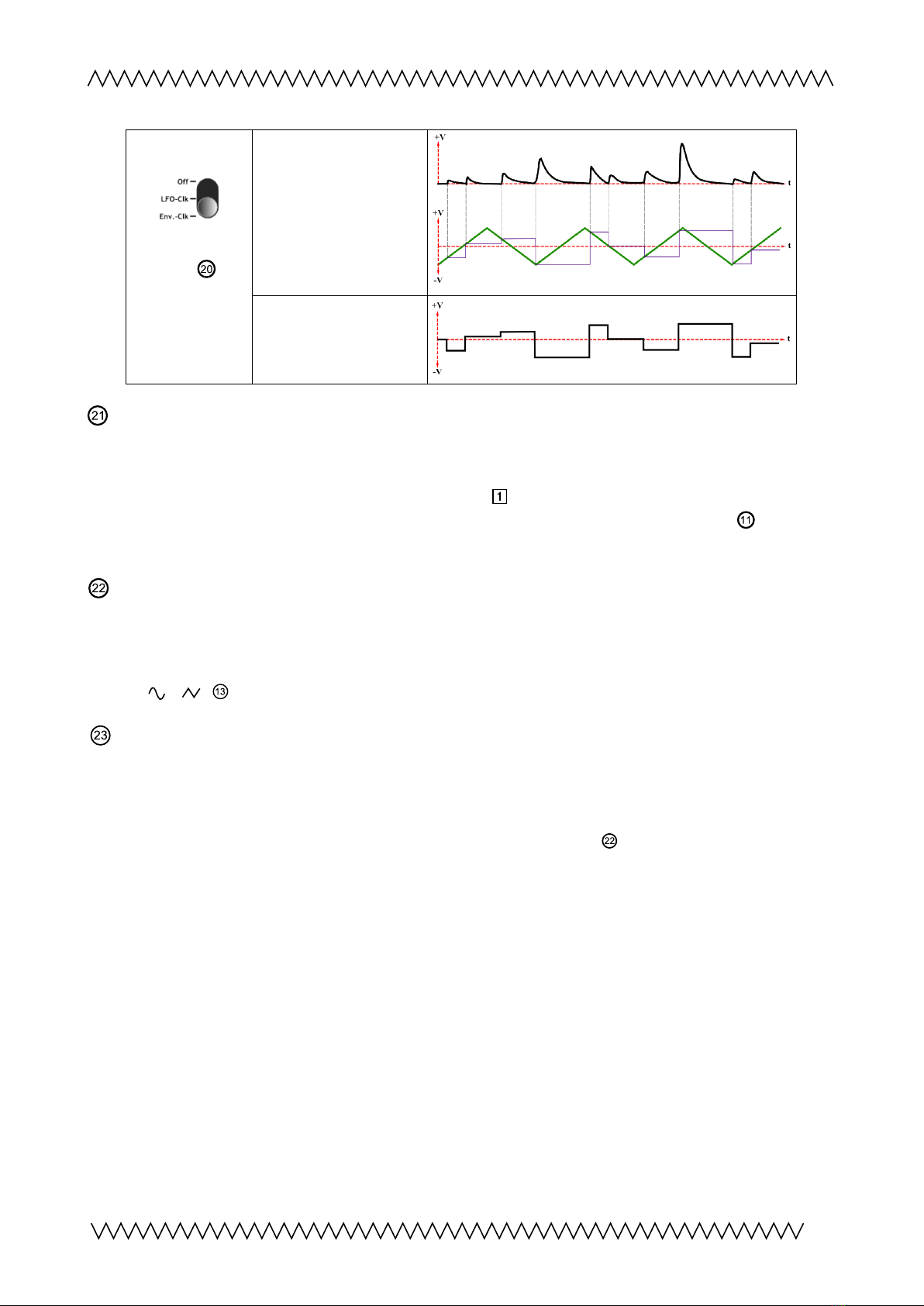
Switch
'S+H'
in lower position
The en elope follower
(from a certain threshold)
is triggering the S+H
The LFO's triangle output
is the S+H's analog input
The resulting frequency
modulation oltage
1V/octa e minijack input
If intended, the oscillator's frequency can be controlled by an external control oltage, for
example from a modular synthesizer, with 1V/octa e calibration. There is a trimmer abo e this
socket (behind the hole in the casing) for adjustment
2 3 456789
21
10 11 13 14 15 16 17 18 19
20 22
12
Objekt in Pfade:
4
4
14
Falsche Zahlen
4
. The oscillator's 1V/oct. beha iour is not
ery linear o er its whole range, best results will be achie ed with the frequency knob set to ≈
2-5 on its scale.
AM In Dri e knob
Together with the preamp knob, the preamplification for the oscillator's amplitude modulation
input can be adjusted. This 2nd controller is allowing to o erdri e the oscillator's amplitude
modulation input and enhances the sound possibilities, especially in combination with wa efrom
switch ' / ' .
Bicolor LED 'AM'
The green lightning signalizes normal and no o erdri en operation. Red lightning indicates that
the
preamp
is becoming o erdri en, this may result in distortion.
Yellow or orange colors signalize when the
oscillator
's amplitude modulation input comes into
saturation and starts to o erdri e – regarding to knob 'AM In Dri e'
23456789
21
10 11 13 14 15 16 17 18 19
20 22
12
Objekt in Pfade:
4
4
14
Falsche Zahlen
4
.
7
23456789
21
10 11 13 14 15 16 17 18 19
20 22
12
Objekt in Pfade:
4
4
14
Falsche Zahlen
4
2 3 456789
21
10 11 13 14 15 16 17 18 19
20 22
12
Objekt in Pfade:
4
4
14
Falsche Zahlen
48
9
10
11
12
23
23456789
21
10 11 13 14 15 16 17 18 19
20 22
12
Objekt in Pfade:
4
4
14
Falsche Zahlen
4
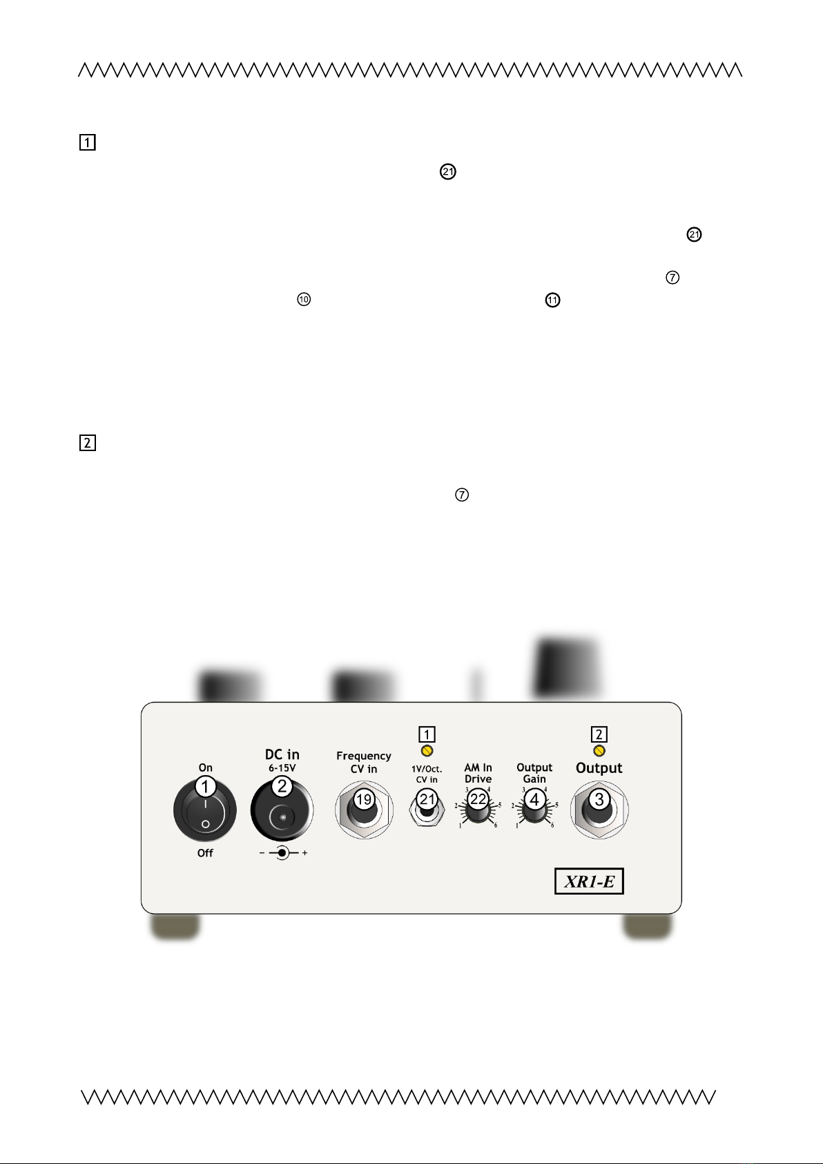
1V/Octa e calibration trimmer
If required, the 1V/octa e matching of minijack input (on the backside) can be calibrated by the
trimmer behind the hole (use a tiny screwdri er).
Calibration suggestion
(after a warming-up of ca 5-10mins)
:
Connect a CV source both to a tuned reference oscillator and to the XR1-E’s 1V/oct. input .
1. Generate a tone of ca 800-1000Hz by the tuned oscillator with e.g. a 1V/oct-keyboard and
compare it with the simultaniously sounding
XR1-E
(knob ‘Carrier Surpression’ fully cw
or ccw; frequency switch : ‘hi’; Setting on knob ‘Frequency’ scale: ≈ 4-5). Calibrate
the XR1-E’s or the other oscillator’s pitch until they are in tune together.
2. Play a note or tune the CV source 2-3 octa es higher. If both tones are not exactly
matching, adjust this trimmer they are in pitch.
3. Repeat procedure from step 1, until best matching is achie ed.
Carrier Surpression knob 0-adjustment trimmer
(new from Re .5.3)
Calibrates the 0-point of the knob ‘Carrier Surpression’ . With the knob in center position
(denter locked) and no input applied, the carrier oscillator signal should be as small as possible. If
required, the 0-point can be readjusted by this trimmer (after a warmng-up of 5-10min).
Back Side View
8
2 3 456789
21
10 11 13 14 15 16 17 18 19
20 22
12
Objekt in Pfade:
4
4
14
Falsche Zahlen
4
2 3 456789
21
10 11 13 14 15 16 17 18 19
20 22
12
Objekt in Pfade:
4
4
14
Falsche Zahlen
4

About Ring Modulation
'Ring modulation' and 'amplitude modulation' are different expressions for almost the same
operation, the
multiplication
of two signals. The audio result is both identical.
The difference between the 2 expressions is: 'Amplitude modulation' describes the multiplication
of
any
kind of analog signals, therefore such as control (DC) oltages; while 'ring modulation' is a
term for the special case of multiplication of two audio signals (AC) with each other.
Each alue of a carrier signal,
C
, is multiplied by a modulator signal,
M
, to create a new
ring-
modulated
signal,
R
:
R(t) = C(t) x M(t)
(Wikipedia)
Due to the
XR1-E ,
the internal oscillator tone
or
is multiplied with the audio input.
Examples
Input (=modulator) signal frequency >> oscillator (carrier) frequency ( ):
Input signal: metallophone
he volume of the metallophone sound varies with the oscillator amplitude (tremolo).
Input (=modulator) signal frequency << oscillator (carrier) frequency ( )
Input signal: "Base drum" from rhythm machine
The generated effect signal
he volume of the oscillator sound varies with the amplitude of the input signal
Input (=modulator) signal frequency ≤ or ≥ oscillator (carrier) frequency ( )
Input signal: "Mid tom" from rhythm machine
Complexe sound structures are generated, depending on the oscillator frequency.
9

Contact
Christian Günther
Forster Str. 50
10999 Berlin
Phone: ++49 30 61286299
Mobile ++49 178 7699267
www.cg-products.de
XR1-E
website with ideo and soundfiles: http://www.cg-products.de/xr1-e/
Youtube: https://www.youtube.com/watch? =2zDMeQAN_4I
Soundcloud: https://soundcloud.com/cg-products/sets/xr1-e
This documentation is for XR1-E Re .5.3 or further
www.cg-products.de/XR1-E_documentation.pdf
For pre ious ersions please see here:
www.cg-products.de/XR1-E_documentation_Re .4.0.pdf
© Christian Günther 2022
10
Other manuals for XR1-E
2
Table of contents
Other CG Products Synthesizer manuals


