KEYA LT Series User manual

20190711
1
CONTENT
Content--------------------------------------------------------1
Introduction --------------------------------------------------2
Chapter 1 Parameters -----------------------------3
Chapter 2 Installation and Cautions -------------7
Chapter 3 Functions and Operation ------------24
Chapter 4 Maintenance --------------------------27
Chapter 5 Troubleshooting ----------------------28
Chapter 6 Warranty and Service ----------------29

20190711
2
INTRODUCTION
Thank you for choosing LT, AR and GT series steam generator with
well-designed structure, steady performance and convenient installation. To form
the whole set of steam bathing equipment, you need a personal steam bathing
room as well. The steam generator is designed to remove tiredness, relax muscles
and stimulate blood circulation.
For proper installation, operation, maintenance, and the safety of customer as
well, please read all instructions carefully and keep this manual for further
reference.
ATTENION: This appliance is not intended for person with reduced physical,
sensory or mental capabilities, or pregnant women, unless they
get permission from doctor and under supervision.
ATTENION: Children should be supervised to ensure that they do not play
with the appliance.
ATTENTION:Check steam room before restart the controller.
ATTENTION: No smoking or alcohol is allowed inside the steam room
ATTENTION: Leave the steam room immediately when feels uncomfortable
ATTENTION: A ventilation fan is required outside the steam room.

20190711
3
CHAPTER 1 PARAMETERS
1. Models, parameters and dimension
Model
Power
kW
Elements
N*kW
Voltage/Current
V/A
Power
wire
N*mm2
Breaker
A
Room volume
m3
Dimension
(L *W*H)
mm
LT-30
AR3C
3.0
1*3.0
220-240/13.6
3*2.5
16
2-3
395*153*313
LT-40
AR4C
4.0
2*2.0
220-240/18.2
3*2.5
25
3~5
LT-50
AR5C
5.0
2*2.5
220-240/22.7
3*2.5
32
4~6
LT-60
AR6C
6.0
2*3.0
220-240/27.3
3*4.0
40
5~7
3*2.0
380-415/9.1
5*1.5
16
LT-70
AR7C
7.0
2*2.5+1*2.0
220-240/31.8
3*6.0
40
5.5~8
380-415/11.4
5*2.5
16
LT-80
AR8C
8.0
2*2.5+1*3.0
220-240/36.4
3*6.0
60
6.5~9
445*182*313
380-415/13.6
5*2.5
16
LT-90
AR9C
9.0
3*3.0
220-240/36.4
3*10
60
8~11
380-415/13.6
5*2.5
16
LT-105
AR10.5C
10.5
3*2.5+1*3.0
220-240/47.7
3*10
60
9~12
500*200*520
3*2.0+3*1.5
380-415/15.9
5*2.5
25
9~12
LT-120
AR12C
12.0
3*4
220-240/54
3*10
100
9~12
6*2.0
380-415/18.2
5*2.5
25
11~14
LT-150
AR15C
15.0
6*2.5
380-415/22.7
5*2.5
32
13~18
Table 1: Standard series
Model
Power
kW
Elements
N*kW
Voltage/Current
V/A
Power
wire
N*mm2
Breaker
A
Room volume
m3
Dimension
(L *W*H)
mm
LT-40
AR4C
4.0
1*4.0
220-240/18.2
3*2.5
25
3~5
395*153*313
LT-50
AR5C
5.0
1*5.0
220-240/22.7
3*2.5
32
4~6
380-415/7.6
5*1.5
16
LT-60
AR6C
6.0
1*6
220-240/27.3
3*4.0
40
5~7
380-415/9.1
5*1.5
16
LT-70
AR7C
7.0
1*7
220-240/31.8
3*6.0
40
5.5~8
380-415/10.6
5*2.5
16
LT-80
AR8C
8.0
1*8
220-240/36.4
3*6.0
60
6.5~9
445*182*313
380-415/12.1
5*2.5
16
LT-90
AR9C
9.0
1*9
220-240/40.9
3*10.0
60
8~11
380-415/13.6
5*2.5
16

20190711
4
Table 2: Economc Series
Notice: The steam generator can have the automatic drainage function as requirement of customer. If the
customer requires the steam generator to use high Frame or △heating element, please specify your
requirement when placing order.
The steam generator construction:
3456
7
8
9
10
11
12
13
1415
161718
1 2
Figure 1
1.Cover 2.Water level sensor 3.Frame 4.Main board 5.Sub board 6.Wire terminal 7.Element access cover
8.Screw 9.Solenoid valve clamp 10.Inlet solenoid valve 11.Safety valve 12.Drainage valve(Or auto drain
solenoid valve for auto drain model) 13.Draining pipe 14.Heating elements 15.Water tank
16.Insulation 17.Water inlet hose 18.Panel
The steam generator construction to use △heating element
21
18 17 16 15 14
13
1211 10
9
8
7
6
5
4
3

20190711
5
Figure 2
1.Cover 2.Water level sensor 3.Frame 4.Main board 5.Sub board 6.Wire terminal 7.Element access cover
8.Screw 9.Solenoid valve clamp 10.Inlet solenoid valve 11.Safety valve 12.Drainage valve(Or auto drain
solenoid valve for auto drain model) 13.Draining pipe 14.Heating elements(△cover) 15.Water tank
16.Insulation 17.Water inlet hose 18.Panel
The working principle of the steam generator:
910
8
1
2
3
4
5
6
7
11
MAIN PCB
SIDE-BOARD
(RELAY)
TERMINAL
CONTROLLER
POWER SUPPLY
1. Inlet Solenoid Valve 2. Steam Outlet
3. Pressure Safety Valve 4. Heating Elements
5. Drainage valve 6. Water Tank
7. Water Level Sensor 8. Main PCB 9. Relay
10. Terminal 11. Controller
FUSE
220-240V
380-415V
50/60Hz
Figure 3
2. Controller parameters and dimension
Model
Controller
model
Controlling time
range
(minutes)
Temperature controlling
range
Dimension
(mm)
LT series
TC-135
fixed(45)
35C~55C(95~131℉)
100*100*25
TC-135A
01~60(fixed)
35C~55C
110*170*18
AR series
KS30A
fixed(45)
86*86
TM60A
01~60and(fixed)
35C~55C(95~131℉)
124*176*21
Table 3
Notice: the temperature sensor should be installed separately and connected to the controller with wire. We
recommend you to install the controller outside the steam room.
The steam generator can have the automatic drainage function as requirement of customer. During the
drainage process, the LED indicator will blink for KS30Aor “-d” is displayed on the LCD panel for TC-135、
TC-135A、GT-135、TM60A. If the customer requires the steam generator( with KS30A、TC-135、GT-135
controller )to continuously work for long term, please specify your requirement when placing order.
1-60 或长期 over a long period of time

20190711
6
TC-135, GT-135 controllers
Figure 4
TC-135A controller
Figure 5
TM60A controller
Figure 6
CONNECTOR FOR
CONTROL PANEL(6P)
CONNECTOR FOR
TEMP SENSORL(2P)
CONNECTOR FOR
TEMP SENSORL (2P)
CONNECTOR FOR
CONTROL PANEL (6P)
CONNECTOR FOR
CONTROL PANEL (6P)
CONNECTOR FOR
TEMP SENSORL (2P)

20190711
7
CHAPTER 2 INSTALLATION AND CAUTIONS
Cautions:
If the generator is installed at a place where difficult for customer access, the water supply valve must be
easy to access for emergencies.
The solenoid valve can endure 0.06-0.55Mpa (0.6-5.5kgf/cm2) water pressure. To protect the solenoid
valve from extremely high water pressure, please turn down the inlet slightly or install water pressure
relieving valve.
Do not install saddle-backed or needle valves on the inlet. Please drain and clean the pipe before
installation.
No block valve should be installed in the steam pipelines. Strictly no blocked or blended pipe, otherwise
have negative effect on the flow of steam and condensate. The steam pipelines should be installed with a
slight angle so that the condensate can flow back to the generator or the steam head.
Steam generator should be installed indoor to avoid frozen. The generator should be installed and leveled
with the arrow pointing upward at an easy-access place, otherwise do not switch on.
The steam pipeline must be copper pipes, all other material such as plastic, acrylic should not be used
since they cannot endure 150℃or higher. temperature
All inlet and apertures should be sealed to prevent any leakage of steam and to protect the generator and
customers.
Draining water to the steam room from the water tank may cause serious scald and damage the steam
room.
1. Selecting the proper steam generator
In order to achieve comfort and relaxation, as well as energy efficiency, the selection of the correct steam
generator model and size are as critical as design of the steam room itself. The power supply and circuit
protector should be carefully checked to match the parameters of the generator. Please refer to the table 1,table
2 and Chapter 1 Parameters to select the suitable generator and controller for your specification.
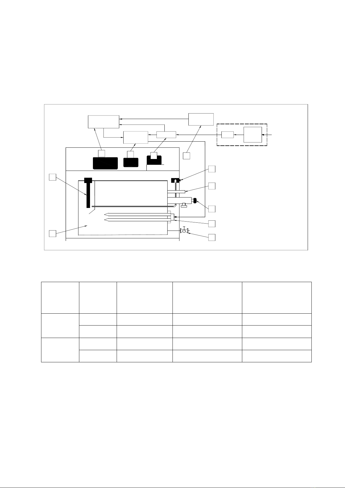
2. Installation of steam generator
Switch off all power supply before installation, and check whether you have the correct model for your
steam room according to table 1 and table 2.
Do not install the generator outdoors, in wet/moist place, freezing, or corrosive place. Do not install the
generator near to inflammables such oil paint, diluents and fuel. Be alert to the steam pipeline and safety
valve since the high temperature of steam is dangerous to customers.
Generator must be level installed.
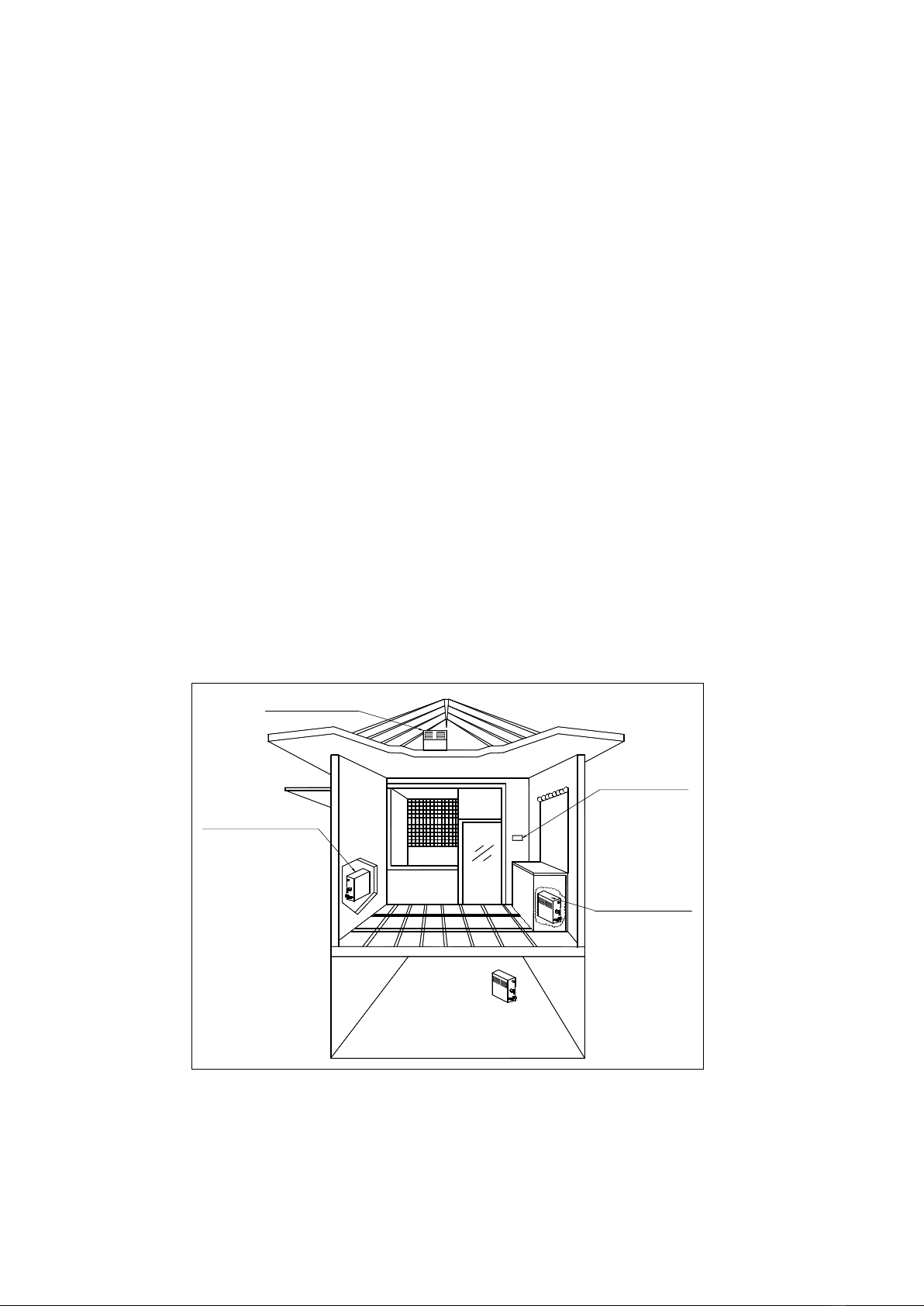
The generator should be installed in a dry and well-ventilated place. It can be installed either on the wall or
on the ground, but must be well fixed. Install the generator as close to steam room as possible, such as in
the closet, under the washing basin or in the basement. (Refer to figure 7).
i. Install the generator on the wall: drill two small holes with diameter of 8 mm on the wall, insert the
expansion screws and then hang the generator on those screws.
ii. Install the generator on the ground or deck: Install the frame on the site and then screw the generator

20190711
8
into the frame.
iii. For better service and maintenance, please install the generator with the nameplate face to front and
leave more than 250 mm space around the generator.
3. Installation of controller and temperature sensor
The controller should be installed with height of 1.2 m outside the steam room but nearby or other place
where easy to operate. Firstly drill a hole on the installation site. Pull the control wire and temperature sensor
wire through the hole, then connect the control wire to the black connector(6P) while connect the temperature
sensor wire to the black connector(2P) of the controller. Finally the controller panel can be glued to wall by the
attached double sided adhesive or apply silicon glue at the back of panel if needed (Refer to figure 8 and 9).
The temperature sensor is used to measure the temperature inside the steam room, so that the generator
can work automatically according to the pre-set temperature and maintain the room temperature constant. The
installation height of the sensor should be about 1.2 –1.5 m from ground. Please drill a hole (diameter 10mm ),
and then nail down the sensor in the steam room (Refer to figure10), pull the sensor wire through the conduit
then connect to the black connector(2P) of the controller.
Caution: The control wire and temperature wire should not be parallel to or intersect with the power wire.
The temperature sensor should not be installed on the side of the wall which is behind the door when the door
is opened and the controller should not be installed in any moist place.
Install in the roof
Install in the closet
Install in the basement
Install under
the washing basin
Suitable
for installation
Figure 7

20190711
9
Figure 8 Figure 9
Figure 10
4. Installation of pipeline
Caution:
If the generator is installed at a place where difficult for customer access, the water inlet valve must be
easy to access for emergencies.
The solenoid valve can endure 0.06-0.55Mpa (0.6-5.5kgf/cm2) water pressure. To protect the solenoid
valve from extremely high water pressure, please turn down the inlet slightly or install water pressure
reducer valve.
Do not install saddle-backed or needle valves on the inlet. Please dredge and clean the pipe before
installation.
No block valve should be installed in the steam pipelines. Strictly no blocked or blended pipe, otherwise
have negative effect on the flow of steam and condensate. The steam pipelines should be installed with a
slight angle so that the condensate can flow back to the generator or the steam head.
Steam generator should be installed outdoors to prevent icing. The generator should be installed and
STEAM HEAD
TEMP SENSOR
1.2 1.5m
TEMP SENSOR
WALL
SENSOR WIRE
IMMOBILIZING SCREW
IMMOBILIZING PLATE

20190711
10
leveled with the arrow pointing upward at an easy-access place, otherwise do not switch on.
The steam pipeline must be copper pipes, all other material such as plastic, acrylic should not be used
since they cannot endure 150℃(302℉) or higher temperature.
All inlet and apertures should be sealed to prevent any leakage of steam and protect the generator and
customers.
Draining water to the steam room from the water tank may cause serious scald and damage the steam
room. A separate draining pipe is required to drain water to the drainage.
All inlet water pipes and steam pipelines should be built according to the National Standard (refer to
Figure 11
) and this should be done before sealing the wall.
Water inlet: First connect the water magnetizer (if applicable) to the water inlet solenoid valve. Then
please use a 1/2’’ flexible stainless steel hose to connect the other side of the water magnetizer and the water
supply pipeline. Do not connect to metal water supply pipeline directly which may damage the water inlet
valve. Only use cold water supply.
Steam outlet: Use no less than 1/2’’ copper pipe to connect the steam head and the steam outlet pipe of
the generator. The pipe should be less than 3 meters long and minimize the number of elbows, otherwise heat
isolating methods should be implemented.

20190711
11
Drain pipe:Please use 1/2’’ copper pipe to connect the drain valve (or drain solenoid valve for Auto drain
model) and the drain pipeline of the house. Similarly, use 1/2’’ copper pipe to connect the safety valve and the
drain pipeline of the house. The drain pipeline should be installed with small angle so as to help residual water
in the steam generator flow to the drain pipe.
Steam head: The steam head should be about 300mm from the ground and at least 150mm from customer
seats. Outlet of the steam head should face downwards. Put the decorating cover onto the outlet pipe and
firmly seal with glue then screw on the steam head. Do not screw too hard and break the cover and steam head.
Auto drain solenoid valve (Only with Auto drain model): Please apply seal glue to the drain pipe
(Part 13 in Figure 1), then screw in the auto drain solenoid valve and plug in the power wire provided (Please
refer to part A in figure 13).

20190711
12
Figure 11
5. Electrical installation
Caution:
All circuits should be installed by licensed electricians and conform to local and national codes.
Power supply must be cut off before installation, maintenance and repair. Press the on/off button on the
generator cannot cut power from the supply.
No additional power supply or wire is allowed to connect to the generator. Do not connect the ground wire
to the neutral wire.
Only the original parts and elements from our factory are allowed to be used in installation, operation,
maintenance and repair.
After the installation of the pipeline and electrical circuits, careful checking must be performed before
switch on the generator.
The generator has been carefully installed, checked and tested in factory, thus customer only need to install
the power wire and control wire.
Connecting the controller to main board:
Open the installation hole on the cover of the generator, lead the wire on the back of controller through
the installation hole, plug the wire into the socket on the main board.(refer to Figure 12.13,14).
Figure 12

20190711
13
ON /O F F
W
W AT ER LE VE L S ENS OR
SU B-BO AR D
M AIN B O A RD
R B
W IR E
CO NT RO L
SO CK ET
W IR E
CO NT RO L
GN D
LO W
W ate r level P ro b e
DRA IN H I GH
DR
45min
J2
D6
D5
P3
P1
P2
D4
D3
D2
D1
J1
ON O N
J5
J6
J3
J1-1
J8
SW 2SW 1
TE S T
ZQ J0 806 No110130
CO NT RO LLE R
No110130
ZQ J0 806
TE S T
SW 1 SW 2
J8
J1-1
J3
J6 J5
ON
ON
J1
D1
D2
D3
D4
P2 P 1 P 3
D5
D6
J2
45min
DR
HIG H
DRA IN
W ate r level P ro b e
LO W
GN D
R30 ,G T30
CO NT RO L
W IR E
SO CK ET
CO NT RO LLE R
CO NT RO L
W IR E
BR M AIN B O A RD
SU B-BO AR D
W AT ER LE VE L S ENS OR
TC -135
TC -135 A
T M 60 A
GT -13 5
W
Figure 13 Figure 14
INSTALLATION OF POWER WIRE
Caution:
The power supply should be 220-240V or 380-415V, 50/60Hz, please refer to the nameplate of the
generator or table 1, 2 of this manual.
The selection of fuse and breaker must strictly follow the data in table 1, 2.
Choose the suitable power wire according to table 1, 2 and local codes.
Power wire connection:
1) Open the installation hole on the front cover of the generator (refer to Figure 12).
2) Lead the three-core power wire(Single phase, 220-240V ,50/60Hz) or five-core power wire
(three phases, 380-415V,50/60Hz) through the installation hole;
3) Plug the wire into the corresponding terminals(refer to Figure 15-25).
Single phase, 220-240V, 50/60Hz power supply: connect the live wire to the terminal labeled as “L” ;
connect the neutral wire to the terminal labeled as “N” ; and connect the ground wire to the terminal labeled as
“ ”.
Three phases, 380-415V, 50/60Hz power supply : connect the L1, L2, L3 wire to the terminal
labeled as “L1”, “L2” and “L3” respectively; connect the neutral wire to the terminal labeled as “N”; and
connect the ground wire to the terminal labeled as “ ”.

20190711
14
HEATING ELEMENTS
DRAINAGE
VALVE INLET
VALVE
SUB-BOARD
4-6kW
CIRCUIT DIAGRAM
HEATING ELEMENT
SW1 SW2
1
2
J3
J1
D1
D2
D3
D4
P2 P1 P3
D5
D6
J2
HIGH
DRAIN
Water level Probe
LOW
GND
GND
3
NL
220-240V~ 50/60Hz
KS30A
ON/OFF
J8
J1-1
J6 J5
ON
ON
45min
DR
TEST
L2L1
WATER
LEVEL
SENSOR
MAIN BOARD
TC-135,TC-135A
TM60A,GT-135
CONTROLLER
POWER SUPPLY
TERMINAL
N L
TERMINAL
240V~ 60Hz
POWER SUPPLY
WRB
Figure 1

20190711
15
SW1 SW2
1
2
J3
J1
D1
D2
D3
D4
P2 P1 P3
D5
D6
J2
HIGH
DRAIN
Water level Probe
LOW
GND
GND
3
NL
N
380-415V~ 50/60Hz
KS30A
ON/OFF
J8
J1-1
J6 J5
ON
ON
45min
DR
TEST
L1 L2 L3
MAIN BOARD
WATER
LEVEL
SENSOR
TC-135,TC-135A
TM60A,GT-135
CONTROLLER
SUB-BOARD
DRAINAGE
VALVE INLET
VALVE
HEATING ELEMENTS
4-6kW 380-415V~ 50/60Hz
CIRCUIT DIAGRAM
HEATING ELEMENT
TERMINAL
POWER SUPPLY
WR B
Figure 16

20190711
16
240V~ 60Hz
POWER SUPPLY
NL
SW1 SW2
GND
GND
LOW
Water level Probe
DRAIN HIGH
J2
D6
D5
P3
P1
P2
D4
D3
D2
D1
J1
J3
KS30A
ON/OFF
J8
J1-1
J6 J5
ON
ON
45min
DR
TEST
1
2
3
MAIN BOARD
TC-135,TC-135A
TM60A,GT-135
CONTROLLER
DRAINAGE
VALVE INLET
VALVE
HEATING ELEMENTS
SUB-BOARD
WATER
LEVEL
SENSOR
220-240V~ 50/60Hz
POWER SUPPLY
7-9kW
CIRCUIT DIAGRAM
HEATING ELEMENT
TERMINAL
L2L1
TERMINAL
TERMINAL
NL
WRB
Figure 17

20190711
17
NL
SW1 SW2
GND
GND
LOW
Water level Probe
DRAIN HIGH
J2
D6
D5
P3
P1
P2
D4
D3
D2
D1
J1
J3
KS30A
ON/OFF
J8
J1-1
J6 J5
ON
ON
45min
DR
TEST
1
2
3
N L1 L2 L3
MAIN BOARD
WATER
LEVEL
SENSOR
TC-135,TC-135A
TM60A,GT-135
CONTROLLER
SUB-BOARD
HEATING ELEMENTS
DRAINAGE
VALVE INLET
VALVE
TERMINAL
380-415V~ 50/60Hz
POWER SUPPLY
7-9kW
CIRCUIT DIAGRAM
HEATING ELEMENT
WRB
Figure 18

20190711
18
NL
LT-30 AR-30
No 110130
ZQJ0806
TEST
SW1 SW2
TM-60A
1
J8
J1-1
J3
J6 J5
ON
ON
J1
D1
D2
D3
D4
P2 P1 P3
D5
D6
J2
45min
DR
HIGH
DRAIN
Water level Probe
LOW
GND
GND
TERMINAL
POWER SUPPLY
220-240V~ 50/60Hz
HEATING ELEMENTS
DRAINAGE
VALVE INLET
VALVE
WATER
LEVEL
SENSOR
W R B
MAIN BOARD
SUB-BOARD
CONTROLLER
TC-135
TC-135A
L1 L2
LT-30 AR-30
POWER SUPPLY
240V~ 60Hz
NL
Figure 19

20190711
19
GND
GND
LOW
Water level Probe
DRAIN HIGH
J2
D6
D5
P3
P1
P2
D4
D3
D2
D1
J1
J3
N
2
1
SW2SW1
4-6kW
L
N
220-240V~ 50/60Hz
J8
J1-1
J6 J5
ON
ON
45min
DR
TEST
ON/OFF
KS30A
TC-135,TC-135A
TM60A,GT-135
CIRCUIT DIAGRAM
TERMINAL
POWER SUPPLY
HEATING ELEMENTS
DRAINAGE
VALVE INLET
VALVE
WATER
LEVEL
SENSOR
W R B
MAIN BOARD
SUB-BOARD
CONTROLLER
L2L1
TERMINAL
240V~ 60Hz
POWER SUPPLY
L
TERMINAL
Figure 20

20190711
20
L
N
L3L2
L1
380-415V 3N~ 50/60Hz
4.5-.7.5kW 380-415V 3N~ 50/60Hz
GND
GND
LOW
Water level Probe
DRAIN HIGH
J2
D6
D5
P3
P1
P2
D4
D3
D2
D1
J1
J3
N
SW2SW1
ON/OFF
J8
J1-1
J6 J5
ON
ON
45min
DR
TEST
3
2
1
KS30A
TC-135,TC-135A
TM60A,GT-135
TERMINAL
POWER SUPPLY
HEATING ELEMENTS
DRAINAGE
VALVE INLET
VALVE
WATER
LEVEL
SENSOR
W R B
MAIN BOARD
SUB-BOARD
CONTROLLER
CIRCUIT DIAGRAM
Figure 21
This manual suits for next models
12
Table of contents