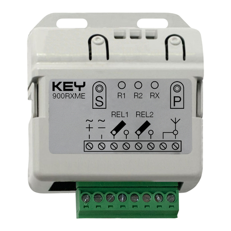
Keyautomation RX4Y User manual

Ricevente radio
Radio receiver
Récepteur radio
Receptor radio
Funkempfänger
Odbiorniki radiowe
Recetor rádio
RX4Y
RXM23Y
RX8
RXM28
Istruzioni ed avvertenze per l’installazione e l’uso
Instructions and warnings for installation and use
Instrucciones y advertencias para su instalación y uso
Anleitungen und Hinweise zu Installation und Einsatz
Instruções e advertências para a instalação e utilização
Instructions et avertissements pour l’installation et l’usage
Management
System
ISO 9001:2008
www.tuv.com
ID 9105043769

I
1 - AVVERTENZE PER LA SICUREZZA
ATTENZIONE – per la sicurezza delle persone è importante rispettare
queste istruzioni e conservarle per utilizzi futuri.
Leggere attentamente le istruzioni prima di eseguire l’installazione. La progettazione e la
fabbricazione dei dispositivi che compongono il prodotto e le informazioni contenute nel
presente manuale rispettano le normative vigenti sulla sicurezza. Ciò nonostante un’in-
stallazione e una programmazione errata possono causare gravi ferite alle persone che
eseguono il lavoro e a quelle che useranno l’impianto. Per questo motivo, durante l’instal-
lazione, è importante seguire attentamente tutte le istruzioni riportate in questo manuale.
2 - INTRODUZIONE AL PRODOTTO
RICEVENTI RADIO
Le riceventi radio Key Automation sono riceventi a 4 uscite per centrali con connettore SSQ
(RX4Y/RX8) e con morsettiera esterna (RXM23Y/RXM28). Le riceventi accettano trasmet-
titori a codice sso o trasmettitori a codice variabile.
Le riceventi RX4Y/RMX23Y/RX8/RXM28 possono essere gestite tramite software e
dispositivo XRMANAGER con versione rmware 2.4 e successive (per 868MHz solo
menu riceventi).
Attenzione: qualsiasi altro uso diverso da quello descritto e in condizioni ambientali
diverse da quelle riportate in questo manuale è da considerarsi improprio e vietato.
CODICE DESCRIZIONE
RX4Y Ricevente a innesto 4 uscite, 433.92 MHz. Memoria massima 1000 codici
RXM23Y Ricevente esterna 2 uscite 433.92 MHz. Memoria massima 1000 codici
RX8 Ricevente a innesto 4 uscite, 868.3 MHz. Memoria massima 1000 codici
RXM28 Ricevente esterna 2 uscite 868.3 MHz. Memoria massima 1000 codici
CARATTERISTICHE TECNICHE 900RX4Y 900RX8 900RXM23Y 900RXM28
Decodica FIX/ROLLING
Compatibilità trasmettitori SUB/PLAY/ORION SUB/PLAY SUB/PLAY/ORION SUB/PLAY
Frequenza 433.92 MHz 868.3 MHz 433.92 MHz 868.3 MHz
Alimentazione 5 Vdc 12 ÷ 24 Vac / 12 ÷ 35 Vdc
Assorbimento a riposo 16 mA 41 mA @ 24 Vac / 20 mA @ 24 Vdc
Assorbimento massimo 27 mA 45 mA @ 24 Vac / 27 mA @ 24 Vdc
Impedenza di ingresso 50 Ω
Uscite 4 2
Uscite relè - 24 Vdc, 1 A MAX, NORM. APERTO
Sensibilità -108 dB
Temperatura di funzionamento -20°+55° C
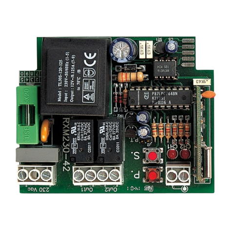
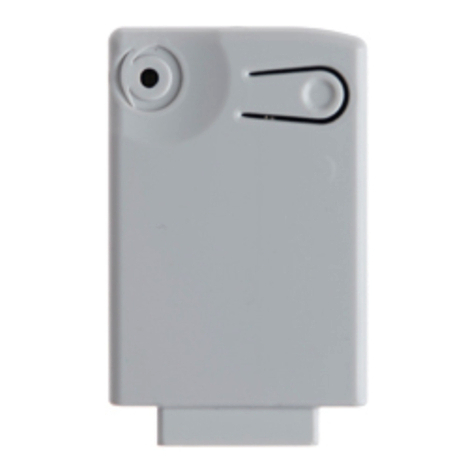
PRINCIPALI COMPONENTI
RX4Y/RX8 RXM23Y/RXM28
3 - VERIFICHE PRELIMINARI
ATTENZIONE – prima di installare il prodotto vericare e controllare i seguenti punti:
• Vericare che la supercie su cui ssare il dispositivo sia solida e non pemetta vibrazioni
• Utilizzare collegamenti elettrici adeguati alle correnti richieste
• Vericare che l’alimentazione rispetti i valori delle caratteristiche tecniche
• Collegare un’antenna tipo ANTS433; senza antenna la portata si riduce a pochi metri
L’antenna deve essere installata più in alto possibile e in presenza di strutture
metalliche o cemento armato va installata al di sopra di queste. Il cavo dell’antenna
deve essere di tipo RG58 con lunghezza massima di 10 m
• Se non fosse possibile installare un’antenna si può migliorare la portata discretamente
collegando un lo elettrico mantenendolo disteso.
4 - INSTALLAZIONE DEL PRODOTTO
Collegare la ricevente radio in assenza di alimentazione e per i modelli RX4Y/RX8
controllare il verso di inserimento seguendo le istruzioni della centrale su cui la
ricevente va innestata.
Attenzione: in alcune centrali il coperchio del modello RX4Y/RX8 va rimosso.
Seguire le istruzioni della centrale di riferimento.
Il primo radiocomando inserito decide il tipo di codica (codice sso o codice va-
riabile). All’accensione la ricevente emette un numero di lampeggi per indicare la
codica dei radiocomandi memorizzati:
• 1 lampeggio lungo = memoria vuota
• 2 lampeggi veloci = codice sso
• 3 lampeggi veloci = codice variabile
4.1 MEMORIZZAZIONE DI UN RADIOCOMANDO
ATTENZIONE: Attivando la fase di memorizzazione qualsiasi trasmettitore nel campo
di ricezione può essere memorizzato. Per ridurre la portata della ricevente scollegare
temporaneamente l’antenna.
4.2 CANCELLAZIONE DI UN RADIOCOMANDO
4.3 CANCELLAZIONE DI TUTTA LA MEMORIA DELLA RICEVENTE/
RESET DELLA RICEVENTE
4.4 MEMORIZZAZIONE A DISTANZA DI UN RADIOCOMANDO
CON RADIOCOMANDO GIÀ IN MEMORIA
É possibile memorizzare un trasmettitore senza accedere al ricevitore. É necessario disporre
di un trasmettitore precedentemente memorizzato e seguire la procedura sottoindicata.
FASE DESCRIZIONE ESEMPIO
1Premere il pulsante della ricevente no a quando si
accende il LED (circa 3 secondi) (>3s)->
2Entro 7 secondi premere un tasto del radiocomando
che si vuole cancellare no a quando il LED sulla rice-
vente si spegne. Rilasciare il tasto del radiocomando ->
3Dopo circa 1 secondo dal rilascio del tasto il LED sulla
ricevente comincia a lampeggiare 0,5s 0,5s
4Confermare la cancellazione premendo il pulsante del-
la ricevente
5Se la cancelllazione è andata a buon ne la ricevente
emetterà 1 lampeggio lungo 3s
Nota Dopo 7 secondi di inattività la ricevente esce automati-
camente dalla fase di cancellazione
FASE DESCRIZIONE ESEMPIO
1Premere e mantenere premuto il pulsante della rice-
vente no a quando si accende il LED (circa 3 secondi)
e poi si spegne (circa 3 secondi). Rilasciare il tasto (>3s)-> (>3s)->
2Dopo circa 1 secondo dal rilascio del tasto il LED sulla
ricevente inizia a lampeggiare (1s)+ (1s)+
3
Per la cancellazione di tutta la memoria premere il ta-
sto della ricevente in corrispondenza del terzo lampeg-
gio oppure per resettare le 4 uscite e riportarle nella
modalità di fabbrica monostabili premere il tasto in
corrispondenza del quinto lampeggio
4Se la cancelllazione/reset è andata a buon ne la rice-
vente emetterà 1 lampeggio lungo
FASE DESCRIZIONE ESEMPIO
1Premere per almeno 5 secondi il tasto del nuovo radio-
comando che si vuole memorizzare >5s
2Premere per almeno 3 secondi il tasto del vecchio radio-
comando che si vuole copiare (se la precendente fase 1
è andata a buon ne l’automazione non si muove) >3s
3Premere per almeno 3 secondi il tasto del nuovo radio-
comando che si vuole memorizzare >3s
4Premere per almeno 3 secondi il tasto del vecchio ra-
diocomando che si vuole copiare per confermare ed
uscire dalla fase di programmazione >3s
Nota Dopo 7 secondi di inattività la ricevente esce automati-
camente dalla fase di programmazione
LED
VERDE LED
VERDE
TASTO TASTO
5 - COLLAUDO E MESSA IN SERVIZIO
L’impianto può essere messo in servizio dopo il collaudo di un tecnico qualicato che deve
effettuare le prove richieste dalla normativa di riferimento in funzione dei rischi presenti,
vericando il rispetto di quanto previsto dalle normative dell’applicazione.
FASE DESCRIZIONE ESEMPIO
1
Premere e rilasciare il pulsante della ricevente per un
numero di volte uguale all’uscita che si vuole attivare:
1 volta per l’uscita 1,
2 volte per l’uscita 2,
3 volte per l’uscita 3,
4 volte per l’uscita 4,
5 volte per l’uscita PREIMPOSTATA (tasto 1 = uscita 1,
tasto 2 = uscita 2, tasto 3 = uscita 3, tasto 4 = uscita 4)
Per conoscere la funzione attivata dall’uscita della ri-
cevente fare riferimento al manuale della centrale o
dispositivo su cui la ricevente verrà installata
+ +
2Il LED sul ricevitore effettua un numero di lampeggi
corrispondente all’uscita selezionata intervallati da una
pausa di 1 secondo + 1s +1s
3Entro 7 secondi premere per almeno 2 secondi il tasto
del radiocomando che si vuole memorizzare 2s
4Se la memorizzazione è andata a buon ne la riceven-
te emetterà un lampeggio lungo 3s
5Per memorizzare un altro radiocomando sulla stessa
uscita ripetere il punto 3
Nota Dopo 7 secondi di inattività la ricevente esce automati-
camente dalla fase di programmazione
+ (~)
- (~)
12/24
Vac/Vdc
OUT 1
OUT 2
J1: = 12 Vac/Vdc
= 24Vac/Vdc
OUT1-OUT2= uscita monostabile impulsiva
J1
La procedura di copia a distanza deve essere eseguita nell’area servita della ricevente.

GBGB
1 - SAFETY WARNINGS
CAUTION – to ensure personal safety it is important to follow these instructions
and keep them for future reference.
Read the instructions carefully before proceeding with installation. The design and ma-
nufacture of the devices making up the product and the information in this manual are
compliant with current safety standards. However, incorrect installation or programming
may cause serious injury to those working on or using the system. Compliance with the
instructions provided here when installing the product is therefore extremely important.
2 - INTRODUCING THE PRODUCT
RADIO RECEIVERS
Key Automation radio receivers are 4-output receivers for control units with SSQ (RX4Y/
RX8) connector and with external terminal board (RXM23Y/RXM28). Receivers accept
xed or variable code transmitters.
The receivers RX4Y/RMX23Y/RX8/RXM28 can be managed via the software and XR-
MANAGER device with rmware versions 2.4 and later (for 868MHz receiver menu
only).
Warning: any use other than as specied herein or in environmental conditions
other than as stated in this manual is to be considered improper and is prohibited.
CODE DESCRIPTION
RX4Y Plug-in receiver, 4 outputs, 433.92 MHz. Maximum memory capacity 1000 codes
RXM23Y External receiver, 2 outputs 433.92 MHz. Maximum memory capacity 1000 codes
RX8 Plug-in receiver, 4 outputs, 868.3 MHz. Maximum memory capacity 1000 codes
RXM28 External receiver, 2 outputs 868.3 MHz. Maximum memory capacity 1000 codes
TECHNICAL SPECIFICATIONS 900RX4Y 900RX8 900RXM23Y 900RXM28
Decoding FIX/ROLLING
Compatible transmitters SUB/PLAY/ORION SUB/PLAY SUB/PLAY/ORION SUB/PLAY
Frequency 433.92 MHz 868.3 MHz 433.92 MHz 868.3 MHz
Power 5 Vdc 12 ÷ 24 Vac / 12 ÷ 35 Vdc
Idle consumption 16 mA 41 mA @ 24 Vac / 20 mA @ 24 Vdc
Max consumption 27 mA 45 mA @ 24 Vac / 27 mA @ 24 Vdc
Input impedance 50 Ω
Outputs 4 2
Relay outputs - 24 Vdc, 1 A MAX, NORMALLY OPEN
Sensitivity -108 dB
Operating temperature -20°+55° C
MAIN COMPONENTS
RX4Y/RX8 RXM23Y/RXM28
3 - PRELIMINARY CHECKS
WARNING - before installing the product, perform the following checks and in-
spections:
• Check that the intended mounting surface is solid and does not allow vibrations
• Use electrical connections suitable for the currents required
• Check that the power supply conforms to the values in the technical specications
• Connect a type ANTS433 antenna; without an antenna, the range is cut to a few metres.
The antenna must be installed as high up as possible and above any metal or reinforced
concrete structures. The antenna cable must be type RG58 and no more than 10 metres long.
• If it is not possible to t an antenna, the range can be increased signicantly by connecting
an electric cable and keeping it straight.
4 - INSTALLING THE PRODUCT
Connect the radio receiver with the power supply disconnected and for RX4Y/RX8
models check the connection position following the instructions on the control
unit to which the receiver is to be connected.
Warning: in some control units, the cover of the RX4Y/RX8 model must be re-
moved.
Follow the instructions of the control unit concerned.
The rst remote control sets the type of encoding (xed or variable code). When
powered up, the receiver ashes to indicate the type of encoding used by the
remote controls in its memory:
• 1 long ash = memory empty
• 2 quick ashes = xed code
• 3 quick ashes = variable code
4.1 MEMORISING A REMOTE CONTROL
WARNING: When the memorisation phase is activated, any transmitter within the
reception range may be memorised. To reduce the receiver’s range, disconnect the
antenna temporarily.
4.2 DELETING A REMOTE CONTROL
4.3 CLEARING THE ENTIRE RECEIVER MEMORY/ RECEIVER RESET
4.4 REMOTE MEMORISATION OF A REMOTE CONTROL WITH
A REMOTE CONTROL ALREADY MEMORISED
A transmitter can be memorised without accessing the receiver. The user needs to
have a transmitter memorised previously, after which the procedure is as described
below. The remote copy procedure must be carried out in the area served by the receiver.
PH. DESCRIPTION EXAMPLE
1Press the button on the receiver until the LED lights up
(about 3 seconds) (>3s)->
2Press the key of the remote control to be deleted within
7 seconds, holding it down until the LED on the recei-
ver goes out. Release the remote control key ->
3About 1 second after the key is released, the LED on
the receiver starts to ash 0,5s 0,5s
4Conrm the deletion by pressing the button on the re-
ceiver
5If the deletion has been successful, the receiver will
give one long ash 3s
N.B. If no commands are given for 7 seconds, the receiver
automatically quits the programming mode
PH. DESCRIPTION EXAMPLE
1Press the button on the receiver and hold it down until
the LED lights up (about 3 seconds) and then goes out
(about 3 seconds). Release the key (>3s)-> (>3s)->
2About 1 second after the key is released, the LED on
the receiver starts to ash (1s)+ (1s)+
3To clear the entire memory, press the receiver button on
the third ash, or to reset the 4 outputs and restore the de-
fault monostable settings, press the button on the fth ash
4If the deletion/reset has been successful, the receiver
will give one long ash
PH. DESCRIPTION EXAMPLE
1Press the key of the new remote control to be memori-
sed, holding it down for at least 5 seconds >5s
2Press the key of the old remote control to be copied (if
phase 1 has been successful, the automation system
will not respond) >3s
3Press the key of the new remote control to be memori-
sed, holding it down for at least 3 seconds >3s
4Press the key of the old remote control to be copied,
holding it down for at least 3 seconds, to conrm and
quit the programming mode >3s
N.B. If no commands are given for 7 seconds, the receiver
automatically quits the programming mode
5 - TESTING AND COMMISSIONING
The system may be put into operation after testing by a qualied technician, who must
perform the tests required by the relevant standards in relation to the risks present, to
check that the installation complies with the relevant regulatory requirements.
PH. DESCRIPTION EXAMPLE
1
Press and release the receiver button a number of ti-
mes equal to the number of the output to be activated:
once for output 1,
twice for output 2,
three times for output 3,
four times for output 4
ve times for output PRESET (button 1 = output 1, but-
ton 2 = output 2, button 3 = output 3, button 4 = output 4)
To nd out which function the receiver output activa-
tes, refer to the manual of the control unit or device on
which the receiver is to be installed
+ +
2The LED on the receiver will ash a number of times
equal to the number of the output selected, with 1 se-
cond pauses between ashes + 1s +1s
3Press the key of the remote control to be memorised
within 7 seconds, holding it down for at least 2 seconds 2s
4If the memorisation has been successful, the receiver
will give one long ash 3s
5To memorise another remote control on the same ou-
tput, repeat point 3
N.B. If no commands are given for 7 seconds, the receiver
automatically quits the programming mode
J1: = 12 Vac/Vdc
= 24Vac/Vdc
OUT1-OUT2= impulsive monostable output
LED
GREEN LED
GREEN
KEY KEY
+ (~)
- (~)
12/24
Vac/Vdc
OUT 1
OUT 2
J1

FI
1 - CONSIGNES DE SÉCURITÉ
ATTENTION – pour la sécurité des personnes, il est important de respecter ces
instructions et de les conserver pour pouvoir les consulter ultérieurement.
Lire attentivement les instructions avant d’effectuer l’installation. La conception et la fa-
brication des dispositifs qui composent le produit et les informations contenues dans ce
guide respectent les normes de sécurité en vigueur. Néanmoins, une installation et une
programmation erronées peuvent causer de graves blessures aux personnes qui exécu-
tent le travail et à celles qui utiliseront l’installation. C’est pourquoi il est important, durant
l’installation, de suivre scrupuleusement toutes les instructions fournies dans ce guide.
2 - PRÉSENTATION DU PRODUIT
RÉCEPTEURS RADIO
Les récepteurs radio Key Automation sont des récepteurs à 4 sorties pour des logiques
de commande à connecteur SSQ (RX4Y/RX8) et bornier extérieur (RXM23Y/RXM28).
Les récepteurs acceptent des émetteurs à code xe ou des émetteurs à code variable.
Les récepteurs RX4Y/RMX23Y/RX8/RXM28 peuvent être gérés au moyen du logiciel
et du dispositif XRMANAGER à partir de la version 2.4 du microgramme (pour 868MHz
menu récepteurs uniquement).Attention: toute utilisation différente de celle qui
est décrite ou dans des conditions ambiantes différentes de celles qui sont indi-
quées dans ce guide doit être considérée comme impropre et interdite.
CODE DESCRIPTION
RX4Y Récepteur embrochable 4 sorties, 433.92 MHz. Mémoire maximale 1000 codes
RXM23Y Récepteur extérieur 2 sorties 433.92 MHz. Mémoire maximale 1000 codes
RX8 Récepteur embrochable 4 sorties 868.3 MHz. Mémoire maximale 1000 codes
RXM28 Récepteur extérieur 2 sorties 868.3 MHz. Mémoire maximale 1000 codes
CARACTÉR. TECHNIQUES 900RX4Y 900RX8 900RXM23Y 900RXM28
Décodage FIX/ROLLING
Compatibilité des émetteurs SUB/PLAY/ORION SUB/PLAY SUB/PLAY/ORION SUB/PLAY
Fréquence 433.92 MHz 868.3 MHz 433.92 MHz 868.3 MHz
Alimentation 5 Vdc 12 ÷ 24 Vac / 12 ÷ 35 Vdc
Absorption au repos 16 mA 41 mA @ 24 Vac / 20 mA @ 24 Vdc
Absorption max 27 mA 45 mA @ 24 Vac / 27 mA @ 24 Vdc
Impédance d’entrée 50 Ω
Sorties 4 2
Sorties relais - 24 Vdc, 1 A MAX, NORM. OUVERT
Sensibilité -108 dB
Température de fonctionnement -20°+55° C
PRINCIPAUX COMPOSANTS
RX4Y/RX8 RXM23Y/RXM28
3 - VÉRIFICATIONS PRÉALABLES
ATTENTION – avant d’installer le produit, vérier et contrôler les points suivants:
• Vérier que la surface sur laquelle sera xé le dispositif est solide et empêchera les vibrations
• Utiliser des câblages électriques adaptés aux courants nécessaires
• Vérier que l’alimentation est conforme aux valeurs des caractéristiques techniques
• Connecter une antenne type ANTS433 ; sans antenne, la portée se réduit à quelques mètres.
L’antenne doit être installée le plus haut possible et, s’il y a des structures
métalliques ou en béton armé, elle doit être positionnée au-dessus. Le câble de
l’antenne doit être du type RG58 avec une longueur maximale de 10 m.
• S’il n’est pas possible d’installer une antenne, on peut améliorer assez bien la portée
en raccordant un l électrique et en le laissant déroulé.
4 - INSTALLATION DU PRODUIT
Connecter le récepteur radio avec l’alimentation coupée et, pour les modèles
RX4Y/RX8, contrôler le sens d’introduction en suivant les instructions de la logi-
que de commande à laquelle le récepteur doit être branché.
Attention : sur certaines logiques de commande, le couvercle du modèle RX4Y
/RX8 doit être retiré. Suivre les instructions de la logique de commande de
référence.
La première radiocommande connectée détermine le type de codage (code xe
ou code variable). Quand on allume le récepteur, il émet un certain nombre de
clignotements pour indiquer le codage des radiocommandes mémorisées:
• 1 clignotement long = mémoire vide
• 2 clignotements rapides = code xe
• 3 clignotements rapides = code variable
4.1 MÉMORISATION D’UNE RADIOCOMMANDE
ATTENTION : En activant la phase de mémorisation, n’importe quel émetteur situé
dans le champ de réception peut être mémorisé. Pour réduire la portée du
récepteur, déconnecter temporairement l’antenne.
4.2 EFFACEMENT D’UNE RADIOCOMMANDE
4.3 EFFACEMENT DE TOUTE LA MÉMOIRE DU RÉCEPTEUR/
RÉINITIALISATION DU RÉCEPTEUR
4.4 MÉMORISATION À DISTANCE D’UNE RADIOCOMMANDE
AVEC UNE RADIOCOMMANDE DÉJÀ MÉMORISÉE
PH. DESCRIPTION EXEMPLE
1Presser la touche du récepteur jusqu’à ce que la DEL
s’allume (3 secondes environ) (>3s)->
2
Dans les 7 secondes qui suivent, presser une touche
de la radiocommande que l’on veut effacer jusqu’à ce
que la DEL sur le récepteur s’éteigne. Relâcher la tou-
che de la radiocommande
->
3Environ une seconde après que la touche a été
relâchée, la DEL présente sur le récepteur commence
à clignoter 0,5s 0,5s
4Conrmer l’effacement en pressant la touche du
récepteur
5Si l’effacement a été correctement effectué, le récep-
teur émettra 1 clignotement long 3s
Rem. Au bout de 7 secondes d’inactivité, le récepteur sort
automatiquement de la phase d’effacement
PH. DESCRIPTION EXEMPLE
1Presser sans le relâcher la touche du récepteur ju-
squ’à ce que la DEL s’allume (3 secondes environ) puis
s’éteigne (3 secondes environ). Relâcher la touche (>3s)-> (>3s)->
2Environ une seconde après que la touche a été
relâchée, la DEL présente sur le récepteur commence
à clignoter (1s)+ (1s)+
3
Pour effacer toute la mémoire, presser la touche du récep-
teur au troisième clignotement ou, pour réinitialiser les 4
sorties avec la conguration par défaut monostable, pres-
ser la touche du récepteur au cinquième clignotement
4Si l’effacement/réinitialisation a été correctement ef-
fectué, le récepteur émettra 1 clignotement long
PH. DESCRIPTION EXEMPLE
1Presser pendant au moins 5 secondes la touche de la
nouvelle radiocommande à mémoriser >5s
2
Presser pendant au moins 3 secondes la touche de
l’ancienne radiocommande à copier (si la phase 1
précédente a été correctement effectuée, l’automati-
sme ne s’active pas)
>3s
3Presser pendant au moins 3 secondes la touche de la
nouvelle radiocommande à mémoriser >3s
4Presser pendant au moins 3 secondes la touche de
l’ancienne radiocommande à copier pour conrmer et
sortir de la phase de programmation >3s
Rem. Au bout de 7 secondes d’inactivité, le récepteur sort
automatiquement de la phase de programmation
5 - RÉCEPTION ET MISE EN SERVICE
L’installation peut être mise en service après l’essai de réception coné à un technicien
qualié, qui doit effectuer les essais prescrits par la norme de référence en fonction
des risques présents et s’assurer que l’installation est conforme aux dispositions des
normes.
PH. DESCRIPTION EXEMPLE
1
Presser puis relâcher la touche du récepteur le nombre
de fois correspondant au numéro de la sortie que l’on
veut activer :
1 fois pour la sortie 1,
2 fois pour la sortie 2,
3 fois pour la sortie 3,
4 fois pour la sortie 4,
5 fois pour la sortie PRÉDÉFINIE (bouton 1 = sortie
1, bouton 2 = sortie 2, bouton 3 = sortie 3, bouton 4
= sortie 4)
Pour connaître la fonction activée par la sortie du
récepteur, faire référence au guide de la logique de
commande ou au dispositif sur lequel le récepteur sera
installé
+ +
2La DEL sur le récepteur clignote le nombre de fois cor-
respondant au numéro de la sortie sélectionnée avec
une pause d’une seconde entre chaque clignotement + 1s +1s
3Dans les 7 secondes qui suivent, presser pendant au
moins 2 secondes la touche de la radiocommande que
l’on veut mémoriser 2s
4Si la mémorisation a été correctement effectuée, le
récepteur émettra un clignotement long 3s
5Pour mémoriser une autre radiocommande sur la
même sortie, répéter le point 3
Rem. Au bout de 7 secondes d’inactivité, le récepteur sort
automatiquement de la phase de programmation
J1: = 12 Vac/Vdc
= 24Vac/Vdc
OUT1-OUT2= sortie monostable impulsive
Il est possible de mémoriser un émetteur sans accéder au récepteur. Pour cela, il faut
disposer d’un émetteur mémorisé précédemment et suivre la procédure ci-dessous.
La procédure de copie à distance doit être effectuée dans la zone de couverture du
récepteur.
LED
VERT LED
VERT
TOUCHE TOUCHE
+ (~)
- (~)
12/24
Vac/Vdc
OUT 1
OUT 2
J1

ES
1 – ADVERTENCIAS PARA LA SEGURIDAD
ATENCIÓN – para la seguridad de las personas es importante respetar
estas instrucciones y conservarlas para futuros consultaciones.
Lea detenidamente las instrucciones antes de realizar la instalación. El diseño y la
fabricación de los dispositivos que componen el producto y las informaciones conteni-
das en este manual respetan las normativas vigentes sobre la seguridad. No obstante
esto, una instalación y una programación incorrectas pueden provocar graves heridas
a las personas que realizan el trabajo y a aquellas que utilizarán el sistema. Por dicho
motivo, durante la instalación es importante respetar escrupulosamente todas las in-
strucciones mencionadas en este manual.
2 - INTRODUCCIÓN AL PRODUCTO
RECEPTORES RADIO
Los receptores Key Automación incorporan 4 salidas para centrales con conector
SSQ (RX4Y/RX8) y con regleta exterior (RXM23Y/RXM28). Los receptores aceptan
transmisores con código jo o transmisores con código variable. Los receptores RX4Y/
RMX23Y/RX8/RXM28 pueden controlarse por medio del software y del dispositivo XR-
MANAGER con versión de rmware 2.4 y siguientes (para 868MHz Sólo menú recep-
tores). Atención: un uso diferente de aquel descrito y en condiciones ambientales
diferentes de aquellas indicadas en este manual será considerado inadecuado y
estará prohibido.
CÓDIGO DESCRIPCIÓN
RX4Y Receptor enchufable 4 salidas, 433.92 MHz. Memoria máxima 1000 códigos
RXM23Y Receptor exterior 2 salidas 433.92 MHz. Memoria máxima 1000 códigos
RX8 Receptor enchufable 4 salidas 868.3 MHz. Memoria máxima 1000 códigos
RXM28 Receptor exterior 2 salidas 868.3 MHz. Memoria máxima 1000 códigos
CARACTERÍST. TÉCNICAS 900RX4Y 900RX8 900RXM23Y 900RXM28
Decodicación FIX/ROLLING
Compatibilidad transmisores SUB/PLAY/ORION SUB/PLAY SUB/PLAY/ORION SUB/PLAY
Frecuencia 433.92 MHz 868.3 MHz 433.92 MHz 868.3 MHz
Alimentación 5 Vdc 12 ÷ 24 Vac / 12 ÷ 35 Vdc
Absorción en reposo 16 mA 41 mA @ 24 Vac / 20 mA @ 24 Vdc
Absorción max 27 mA 45 mA @ 24 Vac / 27 mA @ 24 Vdc
Impedancia de entrada 50 Ω
Salidas 4 2
Salidas relé - 24 Vdc, 1 A MAX, NORM. ABIERTO
Sensibilidad -108 dB
Temperatura de funcionamiento -20°+55° C
COMPONENTES PRINCIPALES
RX4Y/RX8 RXM23Y/RXM28
3 – CONTROLES PRELIMINARES
ATENCIÓN – antes de instalar el producto, compruebe y controle los siguientes
puntos:
• Compruebe que la supercie en la que ja el dispositivo sea rme y no produzca vibraciones
• Utilice conexiones eléctricas adecuadas para las corrientes requeridas
• Compruebe que la alimentación respete los valores de las características técnicas
• Conecte una antena tipo ANTS433; sin antena el alcance se reduce a pocos metros.
La antena se debe instalar lo más alto posible y, en presencia de estructuras
metálicas u hormigón armado, se debe instalar por encima de estas. El cable de la
antena debe ser tipo RG58 con una longitud máxima de 10 m.
• Si no fuera posible instalar una antena, es posible mejorar el alcance discretamente
conectando un cable eléctrico y manteniéndolo extendido.
4 - INSTALACIÓN DEL PRODUCTO
Conecte el receptor en ausencia de alimentación y para los modelos RX4Y/RX8
controle el sentido de conexión siguiendo las instrucciones de la central a la se
conecta el receptor.
Atención: en algunas centrales es necesario quitar la cubierta del modelo RX4Y/
RX8. Siga las instrucciones de la central de referencia.
El primer radiomando conectado establece el tipo de codicación (código jo o
código variable). Cuando el receptor se enciende emite un número de destellos
que indican la codicación de los radiomandos memorizados:
• 1 destello prolongado = memoria vacía
• 2 destellos rápidos = código jo
• 3 destellos rápidos = código variable
4.1 MEMORIZACIÓN DE UN RADIOMANDO
ATENCIÓN: Activando la fase de memorización, cualquier transmisor dentro del
campo de recepción puede ser memorizado. Para reducir el alcance del receptor,
desconecte momentáneamente la antena.
4.2 CANCELACIÓN DE UN RADIOMANDO
4.3 CANCELACIÓN DE TODA LA MEMORIA DEL RECEPTOR/
RESTABLECER EL RECEPTOR
4.4 MEMORIZACIÓN A DISTANCIA DE UN RADIOMANDO CON
RADIOMANDO YA MEMORIZADO
FASE DESCRIPCIÓN EJEMPLO
1Presione el pulsador del receptor hasta que se encien-
da el LED (3 segundos aprox.) (>3s)->
2Presione antes de 7 segundos un pulsador del radio-
mando que se desea cancelar hasta que se apague el
LED del receptor. Suelte el pulsador del radiomando ->
3Transcurrido 1 segundo después de haber soltado el
pulsador, el LED del receptor comenzará a destellar 0,5s 0,5s
4Conrme la cancelación presionando el pulsador del
receptor
5Si la cancelación ha sido correcta, el receptor emitirá 1
destello prolongado 3s
Nota Transcurridos 7 segundos de inactividad, el receptor
sale automáticamente de la fase de programación
FASE DESCRIPCIÓN EJEMPLO
1
Presione y mantenga presionado el pulsador del re-
ceptor hasta que se encienda el LED (3 segundos
aprox.) y luego se apague (3 segundos aprox.). Suelte
el pulsador
(>3s)-> (>3s)->
2Transcurrido 1 segundo después de haber soltado el
pulsador, el LED del receptor comenzará a destellar (1s)+ (1s)+
3
Para borrar toda la memoria, presione el pulsador del
receptor en el tercer destello o restablezca las 4 salidas
y ajuste a la conguración predeterminada de fábrica
monoestable, presione el pulsador en el quinto destello
4Si la cancelación/restablecer ha sido correcta, el re-
ceptor emitirá 1 destello prolongado
FASE DESCRIPCIÓN EJEMPLO
1Presione durante 5 segundos como mínimo el pulsa-
dor del nuevo radiomando que se desea memorizar >5s
2
Presione durante 3 segundos como mínimo el pulsa-
dor del radiomando anterior que se desea copiar (si la
fase 1 anterior se produjo correctamente, el automati-
smo no se moverá)
>3s
3Presione durante 3 segundos como mínimo el pulsa-
dor del radiomando nuevo que se desea memorizar >3s
4Presione durante 3 segundos como mínimo el pulsa-
dor del radiomando anterior que se desea copiar para
conrmar y salir de la fase de programación >3s
Nota Transcurridos 7 segundos de inactividad, el receptor
sale
5 – ENSAYO Y PUESTA EN SERVICIO
El sistema puede ponerse en servicio después del ensayo realizado por un técnico
calicado que debe realizar las pruebas requeridas por la Normativa de referencia en
función de los riesgos presentes, comprobando la conformidad de las normativas de
la aplicación.
FASE DESCRIPCIÓN EJEMPLO
1
Presione y suelte el pulsador del receptor durante un
número de veces equivalente a la salida que se desea
activar:
1 vez para la salida 1,
2 veces para la salida 2,
3 veces para la salida 3,
4 veces para la salida 4,
5 veces para la salida PRECONFIGURADO (bóton 1
= salida 1, bóton 2 = salida 2, bóton 3 = salida 3, bóton
4 = salida 4)
Para conocer la función activa de la salida del recep-
tor, consulte el manual de la central o del dispositivo en
el que se instalará el receptor
+ +
2El LED del receptor realiza un número de destellos
correspondiente a la salida seleccionada, con un inter-
valo de pausa de 1 segundo + 1s +1s
3Antes de 7 segundos presione durante 2 segundos
como mínimo el pulsador del radiomando que se de-
sea memorizar 2s
4Si la memorización ha sido correcta, el receptor emitirá
un destello prolongado 3s
5Para memorizar otro radiomando en la misma salida,
repita el punto 3
Nota Transcurridos 7 segundos de inactividad, el receptor
sale automáticamente de la fase de programación
J1: = 12 Vac/Vdc
= 24Vac/Vdc
OUT1-OUT2= salida monoestable impulsiva
Es posible memorizar un transmisor sin acceder al receptor. Es necesario tener a disposición
un transmisor antes memorizado y seguir el procedimiento indicado a continuación.
El procedimiento de copia a distancia debe hacerse en el área servida por el receptor.
LED
VERDE LED
VERDE
PULS. PULS.
+ (~)
- (~)
12/24
Vac/Vdc
OUT 1
OUT 2
J1

DEI
1 - SICHERHEITSHINWEISE
ACHTUNG – für die Sicherheit von Personen ist es wichtig, diese Anleitung
zu beachten und für zukünftige Nutzungen aufzubewahren.
Vor Durchführung der Installation lesen Sie die Anleitung bitte aufmerksam durch. Die Kon-
struktion und die Herstellung der Vorrichtungen, aus denen das Produkt sich zusammen-
setzt, und die in diesem Handbuch enthaltenen Informationen entsprechen den geltenden
Sicherheitsvorschriften. Dennoch können eine falsche Installation und eine falsche Program-
mierung schwerwiegende Verletzungen bei Personen verursachen, die die Arbeit ausführen
und bei denen, die die Anlage benutzen werden. Aus diesem Grund ist es wichtig, während
der Installation aufmerksam alle Anweisungen in diesem Handbuch zu beachten.
2 - EINFÜHRUNG IN DAS PRODUKT
FUNKEMPFÄNGER
Die Key Automation Funkempfänger sind Empfänger mit 4 Ausgängen für Steuerun-
gen mit Steckverbinder SSQ (RX4Y/RX8), und mit externer Klemmenleiste (RXM23Y/
RX28). Die Empfänger sind ausgelegt für Sender mit feststehendem Code oder Sender
mit variablem Code. Die Empfänger RX4Y/RMX23Y/RX8/RXM28 können mit der Sof-
tware und mit dem XRMANAGER Gerät mit Firmwareversion ab 2.4 verwaltet werden
(für 868MHz nur Receiver-Menü).
Achtung: Jeder andere als der in diesem Handbuch beschriebene Gebrauch und
in anderen als darin genannten Umgebungsbedingungen ist unsachgemäß und
daher untersagt.
CODE BESCHREIBUNG
RX4Y Steckempfänger 4 Ausgänge, 433.92 MHz. Speicher max. 1000 Codes
RXM23Y Externer Empfänger 2 Ausgänge 433.92 MHz. Speicher max. 1000 Codes
RX8 Steckempfänger 4 Ausgänge, 868.3 MHz. Speicher max. 1000 Codes
RXM28 Externer Empfänger 2 Ausgänge 868.3 MHz. Speicher max. 1000 Codes
TECHNISCHE MERKMALE 900RX4Y 900RX8 900RXM23Y 900RXM28
Dekodierung FIX/ROLLING
Senderkompatibilität SUB/PLAY/ORION SUB/PLAY SUB/PLAY/ORION SUB/PLAY
Frequenz 433.92 MHz 868.3 MHz 433.92 MHz 868.3 MHz
Versorgung 5 Vdc 12 ÷ 24 Vac / 12 ÷ 35 Vdc
Verbrauch im Ruhezustand 16 mA 41 mA @ 24 Vac / 20 mA @ 24 Vdc
Verbrauch max 27 mA 45 mA @ 24 Vac / 27 mA @ 24 Vdc
Eingangsimpedanz 50 Ω
Ausgänge 4 2
Relaisausgänge - 24 Vdc, 1 A MAX, NORM. OFFEN
Empndlichkeit -108 dB
Betriebstemperatur -20°+55° C
HAUPTKOMPONENTEN
RX4Y/RX8 RXM23Y/RXM28
3 - VORABPRÜFUNGEN
ACHTUNG – Prüfen und kontrollieren Sie die folgenden Punkte, bevor Sie mit der
Installation beginnen:
• Prüfen, ob die Oberäche, an die das Gerät befestigt wird, stabil ist und keine
Erschütterungen ermöglicht
• Elektrische Anschlüsse verwenden, die für die geforderten Ströme geeignet sind
• Prüfen, ob die Versorgung den Werten der technischen Merkmale entspricht
• Eine Antenne vom Typ ANTS433 anschließen; ohne Antenne verringert sich die
Reichweite auf wenige Meter.
Die Antenne muss so hoch wie möglich angebracht werden, und bei Vorhandensein
von Metallkonstruktionen oder Stahlbeton muss sie oberhalb von diesen installiert
werden. Das Antennenkabel muss vom Typ RG58 sein und darf maximal 10 m lang sein.
• Ist die Installation einer Antenne nicht möglich, kann die Reichweite etwas verbessert
werden, indem ein elektrischer Draht verbunden wird und dieser gespannt bleibt.
4 - INSTALLAZIONE DEL PRODOTTO
Den Funkempfänger ohne Versorung anschließen, und für die Modelle RX4Y/
RX8 die Einsteckrichtung kontrollieren, dazu die Anleitung der Steuerung befol-
gen, in die der Empfänger gesteckt wird.
Achtung: Bei einigen Steuerungen muss der Deckel von Modell RX4Y/RX8
entfernt werden. Die Anleitung der entsprechenden Steuerung beachten.
Die erste eingesteckte Funksteuerung entscheidet über die Kodierungsart (fest-
stehender Code oder variabler Code) Bei Einschaltung blinkt der Empfänger
einige Male, um die Kodierung der gespeicherten Funksteuerung anzuzeigen:
• 1 x langsames Blinken = Speicher leer
• 2 x schnelles Blinken = feststehender Code
• 3 x schelles Blinken = variabler Code
4.1 SPEICHERUNG EINER FUNKSTEUERUNG
ACHTUNG: Wird die Speicherung aktiviert, kann jeder Sender im Empfangsbereich
gespeichert werden. Zur Verringerung der Reichweite des Empfängers die
4.2 LÖSCHEN EINER FUNKSTEUERUNG
4.3 LÖSCHEN DES KOMPLETTEN EMPFÄNGERSPEICHERS/
RESET DES EMPFÄNGERS
4.4 FERNSPEICHERUNG EINER FUNKSTEUERUNG MIT SCHON
GESPEICHERTER FUNKSTEUERUNG
PH. BESCHREIBUNG BEISPIEL
1Die Taste des Empfängers so oft betätigen, bis die
LED aueuchtet (ca. 3 Sekunden) (>3s)->
2
Innerhalb von 7 Sekunden die Taste der Funksteue-
rung, die gelöscht werden soll, so lange betätigen, bis
die LED am Empfänger erlischt. Die Taste der Funk-
steuerung loslassen
->
3Ca. 1 Sekunde nach dem Loslassen der Taste beginnt
die LED am Empfänger zu blinken 0,5s 0,5s
4Das Löschen durch Betätigen der Taste des Empfän-
ger quittieren
5War die Speicherung erfolgreich, meldet der Empfän-
ger dies durch 1 langes Blinken 3s
Hinweis War die Speicherung erfolgreich, meldet der Empfän-
ger dies durch 1 langes Blinken
PH. BESCHREIBUNG BEISPIEL
1Die Taste des Empfängers drücken und gedrückt hal-
ten, bis die LED (ca. 3 Sekunden) aueuchtet und
dann erlischt ( ca. 3 Sekunden). Die Taste loslassen (>3s)-> (>3s)->
2Ca. 1 Sekunde nach dem Loslassen der Taste beginnt
die LED am Empfänger zu blinken (1s)+ (1s)+
3
Zur Löschung des gesamten Speichers beim dritten
Blinken auf die Empfängertaste drücken, oder zum
Rücksetzen der 4 Ausgänge und Rückstellen auf den
monostabilen Werksmodus beim fünften Blinken
4War das Löschen/reset erfolgreich, meldet der
Empfänger dies durch 1 langes Blinken
PH. BESCHREIBUNG BEISPIEL
1Die Taste der neuen Funksteuerung, die gespeichert
werden soll, 5 Sekunden lang betätigen >5s
2Die Taste der alten Funksteuerung, die kopiert werden
soll, 3 Sekunden lang betätigen (war die vorherige
Phase 1 erfolgreich, bewegt der Antrieb sich nicht) >3s
3Die Taste der neuen Funksteuerung, die gespeichert
werden soll, 3 Sekunden lang betätigen >3s
4Die Taste der alten Funksteuerung, die kopiert werden
soll, 3 Sekunden lang betätigen, um die Programmie-
rung zu bestätigen und sie dann zu verlassen >3s
Hinweis Wird innerhalb von 7 Sekunden keine Taste betätigt,
verlässt der Empfänger automatisch die Program-
mierphase
5 - PRÜFUNG UND INBETRIEBNAHME
Die Anlage kann nach erfolgter Prüfung durch einen ausgebildeten Techniker in Betrieb
genommen werden. Dieser muss die von der einschlägigen Vorschrift verlangten Tests
hinsichtlich der vorhandenen Risiken durchführen und prüfen, ob alle Vorgaben der
Vorschriften für die Anwendungen beachtet wurden.
PH. BESCHREIBUNG BEISPIEL
1
Die Taste so oft betätigen und loslassen, wie es der
Nummer des Ausgangs entspricht, der aktiviert werden
soll:
1 mal für Ausgang 1,
2 mal für Ausgang 2,
3 mal für Ausgang 3,
4 mal für Ausgang 4,
5 mal für Ausgang VOREINGESTELLT (Taste 1 =
Ausgang 1, Taste 2 = Ausgang 2, Taste 3 = Ausgang 3,
Taste 4 = Ausgang 4)
Um die vom Ausgang aktivierte Funktion zu kennen,
vgl. das Handbuch der Steuerung oder des Geräts, an
das der Empfänger installiert wird
+ +
2Die LED am Empfänger blinkt mit der Anzahl, die dem
gewählten Ausgang entspricht, unterbrochen von einer
Pause von 1 Sekunde + 1s +1s
3Innerhalb von 7 Sekunden mindestens 2 Sekunden
lang die Taste der Funksteuerung betätigen, die ge-
speichert werden soll 2s
4War die Speicherung erfolgreich, meldet der Empfän-
ger dies durch 1 langes Blinken 3s
5Für die Speicherung einer weiteren Funksteuerung auf
den selben Ausgang ist Punkt 3 zu wiederholen
Hinweis Wird innerhalb von 7 Sekunden keine Taste betätigt,
verlässt der Empfänger automatisch die Program-
mierphase
J1: = 12 Vac/Vdc
= 24Vac/Vdc
OUT1-OUT2= ausgäng monostabiler Impulsausgang
Es kann ein Sender ohne Zugriff auf den Empfänger gespeichert werden. Es ist
erforderlich, über einen vorab gespeicherten Sender zu verfügen, dann wie unten
angegeben verfahren.
Die Fernkopierprozedur muss im Zuständigkeitsbereich des Empfängers durchgeführt
werden.
LED
GRÜN LED
GRÜN
TASTE TASTE
+ (~)
- (~)
12/24
Vac/Vdc
OUT 1
OUT 2
J1
PL
1 - UWAGI DOTYCZĄCE BEZPIECZEŃSTWA
UWAGA – aby zapewnić bezpieczeństwo osób należy stosować się
do niniejszej instrukcji i zachować ją do użytku w przyszłości.
Przed przystąpieniem do instalacji zapoznać się uważnie z treścią instrukcji. Pro-
cesy projektowania i produkcji urządzeń wchodzących w skład produktu, jak też in-
formacje zawarte w niniejszej instrukcji, spełniają wymogi obowiązujących przepisów
bezpieczeństwa. Pomimo tego nieprawidłowa instalacja oraz błędne programowanie
mogą spowodować poważne obrażenia osób wykonujących pracę lub eksploatujących
instalację. Dlatego też podczas instalacji należy rygorystycznie stosować się do
wszelkich zaleceń podanych w niniejszej instrukcji.
2 - INFORMACJE OGÓLNE DOTYCZĄCE PRODUKTU
ODBIORNIKI RADIOWE
Odbiorniki radiowe Key Automation są odbiornikami posiadającymi 4 wyjścia do cen-
trali ze złączem SSQ (RX4Y/RX8) w zewnętrzna listwą zaciskową (RXM23Y/RXM28).
Odbiorniki akceptują nadajniki z kodem stałym lub nadajniki z kodem zmiennym.
Odbiorniki RX4Y/RMX23Y/RX8/RXM28 mogą być sterowane za pomocą oprogramo-
wania i urządzenia XRMANAGER (wersja rmware 2.4 i wyższe - dla 868MHz Menu
tylko odbiorniki).
Uwaga: zabrania się używania produktu do celów innych, niż opisane w niniejszej
instrukcji oraz w warunkach środowiskowych innych, niż określone dla danego
produktu.
KOD OPIS
RX4Y Odbiornik wewnętrzny 4 wyjścia, 433.92 MHz. Maksymalna pojemność pamięci 1000 kodów
RXM23Y Odbiornik zewnętrzny 2 wyjścia 433.92 MHz. Maksymalna pojemność pamięci 1000 kodów
RX8 Odbiornik wewnętrzny 4 wyjścia 868.3 MHz. Maksymalna pojemność pamięci 1000 kodów
RXM28 Odbiornik zewnętrzny 2 wyjścia 868.3 MHz. Maksymalna pojemność pamięci 1000 kodów
DANE TECHNICZNE 900RX4Y 900RX8 900RXM23Y 900RXM28
Dekodowanie FIX/ROLLING
Kompatybilność nadajników SUB/PLAY/ORION SUB/PLAY SUB/PLAY/ORION SUB/PLAY
Częstotliwość 433.92 MHz 868.3 MHz 433.92 MHz 868.3 MHz
Zasilanie 5 Vdc 12 ÷ 24 Vac / 12 ÷ 35 Vdc
Pobór prądu w spoczynku 16 mA 41 mA @ 24 Vac / 20 mA @ 24 Vdc
Pobór prądu max 27 mA 45 mA @ 24 Vac / 27 mA @ 24 Vdc
Impedancja wejścia 50 Ω
Wyjścia 4 2
Wyjścia przekaźnika -24 Vdc, 1 A MAX,NORM. OTWARTY
Czułość -108 dB
Temperatura pracy -20°+55° C
GŁÓWNE KOMPONENTY
RX4Y/RX8 RXM23Y/RXM28
3 - KONTROLE WSTĘPNE
UWAGA – przed zainstalowaniem produktu wykonać następujące kontrole i za-
lecenia:
• Sprawdzić, czy powierzchnia przeznaczona do zamocowania produktu jest solidna i
czy nie przenosi drgań.
• Używać podłączeń elektrycznych dostosowanych do wymaganych wartości prądu.
• Sprawdzić, czy zasilanie posiada wartości określone w parametrach technicznych.
• Podłączyć antenę typu ANTS433; bez użycia anteny zasięg zostaje ograniczony do
kilku metrów.
Antenę należy zamontować na najwyższej możliwej wysokości. W przypadku
występowania konstrukcji metalowych lub ze zbrojonego betonu, antenę należy
zamontować powyżej tych elementów. Przewód elektryczny anteny
powinien być typu RG58 i posiadać maksymalną długość 10 m.
• Jeżeli nie można zamontować anteny, zasięg można zwiększyć poprzez
podłączenie i rozciągnięcie przewodu elektrycznego.
4 - INSTALACJA PRODUKTU
Podłączyć odbiornik radiowy bez doprowadzania zasilania. W przypadku mo-
deli RX4Y/RX8 sprawdzić kierunek wprowadzania, stosując się do instrukcji
dotyczącej centrali, na której montowany jest odbiornik.
Uwaga: w przypadku niektórych centrali należy usunąć pokrywę modelu RX4Y/
RX8. Stosować się do instrukcji dołączonej do odpowiedniej centrali.
Pierwszy wprowadzony pilot decyduje o rodzaju kodowania (kod stały lub kod
zmienny). Po włączeniu odbiornika pojawia się na nim określona sekwencja
mignięć, informując o rodzaju kodowania zapisanych w pamięci pilotów:
• 1 długie mignięcie = pamięć pusta
• 2 szybkie mignięcia = kod stały
• 3 szybkie mignięcia = kod zmienny
4.1 WPROWADZANIE PILOTA DO PAMIĘCI
UWAGA: Po aktywowaniu funkcji wprowadzania pilota do pamięci, w odbiorniku
może zostać zapisany każdy pilot znajdujący się w polu odbioru. Aby ograniczyć
zasięg odbiornika, odłączyć tymczasowo antenę.
4.2 KASOWANIE PILOTA
4.3 CAŁKOWITE KASOWANIE PAMIĘCI ODBIORNIKA/
RESET ODBIORNIKA
4.4 ZDALNE WPROWADZANIE PILOTA DO PAMIĘCI PRZY
POMOCY PILOTA WCZEŚNIEJ WPROWADZONEGO
FAZA OPIS PRZYKŁAD
1Wcisnąć i przytrzymać przycisk odbiornika do momen-
tu zaświecenia się diody LED (ok. 3 sekundy) (>3s)->
2
W ciągu 7 sekund wcisnąć przycisk pilota, który ma
zostać skasowany, i przytrzymać aż do momentu
zgaśnięcia diody LED na odbiorniku. Zwolnić przycisk
pilota
->
3Po upływie ok. 1 sekundy od zwolnienia przycisku, dio-
da LED na odbiorniku zaczyna migać 0,5s 0,5s
4Zatwierdzić kasowanie poprzez wciśnięcie przycisku
odbiorniku
5Jeżeli kasowanie pilota zakończyło się powodzeniem,
na odbiorniku pojawi się 1 długie mignięcie 3s
Uwag. Po 7 sekundach nieaktywności odbiornik kończy auto-
matycznie fazę kasowania
FAZA OPIS PRZYKŁAD
1Wcisnąć i przytrzymać przycisk odbiornika do momen-
tu zaświecenia się diody LED (ok. 3 sekundy) a potem
jej zgaśnięcia (ok. 3 sekundy). Zwolnić przycisk (>3s)-> (>3s)->
2Po upływie ok. 1 sekundy od zwolnienia przycisku, dio-
da LED na odbiorniku zaczyna migać (1s)+ (1s)+
3
W celu całkowitego wykasowania pamięci nacisnąć
przycisk odbiornika w trakcie trzeciego mignięcia kon-
trolki. W celu dokonania resetu 4 wyjść i sprowadzenia
ich do trybu fabrycznego monostabilnego nacisnąć
przycisk w trakcie piątego mignięcia
4Jeżeli kasowanie/reset pilota zakończyło się powodze-
niem, na odbiorniku pojawi się 1 długie mignięcie
FAZA OPIS PRZYKŁAD
1Wcisnąć i przytrzymać przez co najmniej 5 sekund
przycisk nowego pilota, który ma zostać wprowadzony
do pamięci >5s
2
Wcisnąć i przytrzymać przez co najmniej 3 sekun-
dy przycisk starego pilota, który ma zostać skopio-
wany (jeżeli wcześniejsza faza 1 zakończona została
powodzeniem, napęd nie zostanie uruchomiony)
>3s
3Wcisnąć i przytrzymać przez co najmniej 3 sekundy
przycisk nowego pilota, który ma zostać wprowadzony
do pamięci >3s
4
Wcisnąć i przytrzymać przez co najmniej 3 sekundy
przycisk starego pilota, który ma zostać skopiowany,
na znak zatwierdzenia, a następnie zakończyć fazę
programowania
>3s
Uwag. Po 7 sekundach nieaktywności odbiornik kończy auto-
matycznie fazę programowania
5 - ODBIÓR TECHNICZNY ORAZ ODDANIE DO UŻYTKOWANIA
Instalacja może zostać oddana do użytkowania po przeprowadzeniu przez wykwaliko-
wanego technika odbioru technicznego. Technik zobowiązany jest do wykonania testów
wymaganych przepisami wskazanymi w zależności od istniejących zagrożeń oraz do
sprawdzenia, czy instalacja spełnia wymogi określone w mających zastosowanie ure-
gulowaniach.
FAZA OPIS PRZYKŁAD
1
Wcisnąć i zwolnić przycisk odbiornika taką liczbę razy,
która równa jest numerowi wyjścia wybranego do
aktywacji:
1 raz dla wyjścia 1,
2 razy dla wyjścia 2,
3 razy dla wyjścia 3,
4 razy dla wyjścia 4,
5 razy dla wyjścia WSTĘPNE (przycisk 1 = wyjścia 1,
przycisk 2 = wyjścia 2, przycisk 3 = wyjścia 3, przycisk
4 = wyjścia 4)
Aby poznać funkcję aktywowaną przez wyjście odbior-
nika patrz instrukcja centrali lub urządzenia, na którym
zostanie zamontowany odbiornik
+ +
2Znajdująca się na odbiorniku dioda LED błyska taką
liczbę razy, jaka odpowiada numerowi wybranego
wyjścia; błyski przedzielane są pauzą trwającą 1 s + 1s +1s
3W ciągu 7 sekund należy wcisnąć i przytrzymać przez
co najmniej 2 sekundy przycisk pilota, który chcemy
wprowadzić do pamięci 2s
4Jeżeli wprowadzanie pilota do pamięci zakończyło się
powodzeniem, na odbiorniku pojawi się jeden długi błysk 3s
5W celu wprowadzenia do pamięci innego pilota na tym
samym wyjściu, powtórzyć czynności z punktu 3
Uwag. Po 7 sekundach nieaktywności odbiornik kończy auto-
matycznie fazę programowania
J1: = 12 Vac/Vdc
= 24Vac/Vdc
OUT1-OUT2= wyjścia monostabilny impulsywnych
Istnieje możliwość wprowadzenia pilota do pamięci bez dostępu do odbiornika. W tym
celu należy dysponować pilotem, który został już wprowadzony do pamięci, oraz
wykonać poniższą procedurę.Procedurę zdalnego kopiowania należy wykonać w
obszarze obsługiwanym przez odbiornik.
LED
ZIELONY LED
ZIELONY
PRZYCISK PRZYCISK
+ (~)
- (~)
12/24
Vac/Vdc
OUT 1
OUT 2
J1
PTI
1 - AVISOS SOBRE A SEGURANÇA
ATENÇÃO – para a segurança das pessoas é importante respeitar
estas instruções e conservá-las para utilizações futuras.
Ler com atenção as instruções antes de instalar. O projeto e o fabrico dos dispositivos
que compõem o produto e as informações presentes neste manual respeitam as nor-
mas vigentes sobre segurança. Porém, a instalação ou a programação inadequada
podem causar feridas graves às pessoas que fazem o trabalho e às que utilizarão o
sistema. Por este motivo, durante a instalação, é importante seguir com atenção todas
as instruções deste manual.
2 - DESCRIÇÃO DO PRODUTO
RECETORES RÁDIO
Os recetores rádio Key Automation são recetores de 4 saídas para unidades com co-
nector SSQ (RX4Y/RX8) e com placa de terminais externa (RXM23Y/RXM28). Os re-
cetores aceitam transmissores de código xo ou transmissores de código variável. Os
recetores RX4Y/RMX23Y/RX8/RXM28 podem ser controlados através de software e
dispositivo XRMANAGER com versão rmware 2.4 e seguintes (para 868MHz cardápio
só receptores).
Atenção: qualquer outra utilização diferente da descrita e em condições am-
bientais que não respeitem as indicadas neste manual deve ser considerada im-
própria e proibida.
CÓDIGO DESCRIÇÃO
RX4Y Recetor de encaixe 4 saídas, 433.92 MHz. Memória máxima 1000 códigos
RXM23Y Recetor externo 2 saídas 433.92 MHz. Memória máxima 1000 códigos
RX8 Recetor de encaixe 4 saídas 868.3 MHz. Memória máxima 1000 códigos
RXM28 Recetor externo 2 saídas 868.3 MHz. Memória máxima 1000 códigos
CARACTERÍSTICAS TÉCNICAS 900RX4Y 900RX8 900RXM23Y 900RXM28
Decodicação FIX/ROLLING
Compatibilidade transmissores SUB/PLAY/ORION SUB/PLAY SUB/PLAY/ORION SUB/PLAY
Frequência 433.92 MHz 868.3 MHz 433.92 MHz 868.3 MHz
Alimentação 5 Vdc 12 ÷ 24 Vac / 12 ÷ 35 Vdc
Consumo de repouso 16 mA 41 mA @ 24 Vac / 20 mA @ 24 Vdc
Consumo max 27 mA 45 mA @ 24 Vac / 27 mA @ 24 Vdc
Impedância de entrada 50 Ω
Saídas 4 2
Saídas do relé - 24 Vdc, 1 A MAX,NORM. ABERTO
Sensibilidade -108 dB
Temperatura de funcionamento -20°+55° C
PRINCIPAIS COMPONENTES
RX4Y/RX8 RXM23Y/RXM28
3 - CONTROLOS PRELIMINARES
ATENÇÃO – antes de instalar o produto, vericar e controlar os pontos indicados
a seguir:
• Vericar se a superfície na qual o dispositivo será xado é sólida e se não permite vibrações.
• Utilizar ligações elétricas adequadas às correntes necessárias.
• Vericar se a alimentação respeita os valores das características técnicas.
• Ligar uma antena tipo ANTS433; sem antena o alcance reduz-se a poucos metros.
A antena deve ser instalada na posição mais alta possível e se houver estruturas
metálicas ou em betão armado deve ser instalada acima das mesmas. O cabo da
antena deve ser de tipo RG58 com comprimento máximo igual a 10 m.
• Se não for possível instalar uma antena, é possível melhorar ligeiramente o alcance
através da ligação de um o elétrico que deve ser mantido esticado.
4 - INSTALAÇÃO DO PRODUTO
Ligar o recetor rádio com a alimentação desligada e, para os modelos RX4Y/
RX8, controlar o sentido de posicionamento de acordo com as instruções da
unidade em que o recetor será encaixado.
Atenção: em algumas unidades, a tampa do modelo RX4Y/RX8 deve ser retirada.
Seguir as instruções da respetiva unidade.
O primeiro radiocomando posicionado dene o tipo de codicação (código xo
ou código variável). Ao ser ligado, o recetor emite um certo número de sinais
intermitentes para indicar a codicação dos radiocomandos memorizados:
• 1 sinal intermitente longo = memória vazia
• 2 sinais intermitentes rápidos = código xo
• 3 sinais intermitentes rápidos = código variável
4.1 MEMORIZAÇÃO DE UM RADIOCOMANDO
ATENÇÃO: Ativando a fase de memorização, qualquer transmissor no campo
de receção pode ser memorizado. Para reduzir o alcance do recetor desligar
temporariamente a antena.
4.2 ELIMINAÇÃO DE UM RADIOCOMANDO
4.3 ELIMINAÇÃO DE TODA A MEMÓRIA DO RECETOR/
RESET DO RECETOR
4.4 MEMORIZAÇÃO À DISTÂNCIA DE UM RADIOCOMANDO
COM RADIOCOMANDO JÁ MEMORIZADO
FASE DESCRIÇÃO EXEMPLO
1Premir a tecla do recetor até quando se acender o LED
(cerca de 3 segundos) (>3s)->
2Dentro de 7 segundos premir uma tecla do radioco-
mando que se deseja eliminar até quando o LED no
recetor se apagar. Libertar a tecla do radiocomando ->
3Cerca de 1 segundo após libertar a tecla, o LED no
recetor ca intermitente 0,5s 0,5s
4Conrmar a eliminação premindo o botão do recetor
5Se a eliminação for concluída, o recetor emitirá 1 sinal
intermitente longo 3s
Obs. Depois de 7 segundos de inatividade o recetor sai au-
tomaticamente da fase de eliminação
FASE DESCRIÇÃO EXEMPLO
1Premir e manter premido o botão do recetor até quan-
do se acender o LED (cerca de 3 segundos) e depois
se apagar (cerca de 3 segundos). Libertar a tecla (>3s)-> (>3s)->
2Cerca de 1 segundo após libertar a tecla, o LED no
recetor ca intermitente (1s)+ (1s)+
3
Para eliminar toda a memória, premir a tecla do rece-
tor na altura do terceiro sinal intermitente ou para fazer
o reset das 4 saídas e restaurar o modo de fábrica
monoestável, prima a tecla na altura do quinto sinal
intermitente
4Se a eliminação/reset for concluída, o recetor emitirá 1
sinal intermitente longo
FASE DESCRIÇÃO EXEMPLO
1Premir durante pelo menos 5 segundos a tecla do
novo radiocomando que se deseja memorizar >5s
2Premir durante pelo menos 3 segundos a tecla do vel-
ho radiocomando que se deseja copiar (se a fase ante-
rior 1 foi concluída o automatismo não se movimenta) >3s
3Premir durante pelo menos 3 segundos a tecla do
novo radiocomando que se deseja memorizar >3s
4Premir durante pelo menos 3 segundos a tecla do vel-
ho radiocomando que se deseja copiar para conrmar
e sair da fase de programação >3s
Obs. Depois de 7 segundos de inatividade o recetor sai
automaticamente da fase de programação
5 - ENSAIO E COLOCAÇÃO EM SERVIÇO
O sistema pode ser colocado em serviço após o ensaio feito por um técnico qualicado
que deve realizar os testes previstos pela norma de referência de acordo com os riscos
presentes, vericando que sejam respeitadas as normas aplicáveis.
FASE DESCRIÇÃO EXEMPLO
1
Premir e libertar o botão do recetor um número de ve-
zes igual ao número da saída que se deseja ativar:
1 vez para a saída 1,
2 vezes para a saída 2,
3 vezes para a saída 3,
4 vezes para a saída 4,
5 vezes para a saída 5 PRÉ-CONFIGURADA (tecla 1
= saída 1, tecla 2 = saída 2, tecla 3 = saída 3, tecla 4
= saída 4)
Para informações sobre a função ativada pela saída
do recetor, consultar o manual da unidade ou do dispo-
sitivo em que o recetor será instalado
+ +
2O Led no recetor emite um número de sinais intemi-
tentes correspondente à saída selecionada com inter-
valos de 1 segundo + 1s +1s
3Dentro de 7 segundos, premir durante pelo menos
2 segundos a tecla do radiocomando que se deseja
memorizar 2s
4Se a memorização for concluída, o recetor emitirá um
sinal intermitente longo 3s
5Para memorizar um outro radiocomando na mesma
saída, repetir o ponto 3
Obs. Depois de 7 segundos de inatividade o recetor sai au-
tomaticamente da fase de programação
J1: = 12 Vac/Vdc
= 24Vac/Vdc
OUT1-OUT2= saída monoestável impulsiva
É possível memorizar um transmissor sem aceder ao recetor. É necessário ter um
transmissor já memorizado e seguir as instruções abaixo.
O procedimento de cópia à distância deve ser feito na área de alcance do recetor.
LED
VERDE LED
VERDE
TECLA TECLA
+ (~)
- (~)
12/24
Vac/Vdc
OUT 1
OUT 2
J1
DICHIARAZIONE DI INCORPORAZIONE DI QUASI-MACCHINA
DECLARATION OF INCORPORATION OF PARTLY COMPLETED MACHINERY
Key Automation S.r.l.
Via A. Volta, 30 Capitale sociale 154
.000,00 i.v.
30020 Noventa di Piave (VE) Reg. Imprese di Venezia 03627650264
P.IVA 03627650264 C.F. 03627650264 REA VE 326953
Il sottoscritto Nicola Michelin, Amministratore Delegato dell’azienda
The undersigned Nicola Michelin, General Manager of the company
Key Automation srl, Via Alessandro Volta, 30 - 30020 Noventa di Piave (VE) –ITALIA
dichiara che il prodotto tipo:
declares that the product type:
MEMO
Ricevitore multicanale 433,92MHz o 868MHz, codice fisso e rolling code
433MHz or 868MHz rolling & fix code multichannel radio receiver
Models:
Models:
900RX4Y, 900RXM23Y, 900RX8, 900RXM28
E’ conforme a quanto previsto dalle seguenti direttive comunitarie:
Is in conformity with the following community (EC) regulations:
Direttiva macchine /
Machinery Directive
2006/42/EC
Direttiva compatibilità elettromagnetica /
EMC Directive
2014/30/EU
Direttiva bassa tensione /
Low voltage Directive
2014/35/EU
Direttiva radiofrequenza /
R&TTE Directive
1999/05/EC
Direttiva RoHS /
RoHS Directive
2002/95/EC
Secondo quanto previsto dalle seguenti norme armonizzate:
In accordance with the following harmonized standards regulations:
EN 55014-1:2006 + A1:2009 + A2:2011, EN 55014-2:1997 + A1:2001+ A2:2008
ETSI EN 300220-1:2010-02, ETSI EN 300220-2:2010-02
ETSI EN 301489-3:2002, ETSI EN 301489-1:2008
EN 61000-3-2:2006 + A1 + A2:2009, EN 61000-3-3:2008
EN 61000-6-1:2007
EN 60335-1:2012, EN 60335-2-103:2015
EN 62233:2008
Dichiara che la documentazione tecnica pertinente al prodotto è stata redatta conformemente a quanto previsto dalla
direttiva 2006/42/CE Allegato VII parte B e verrà fornita a fronte di una richiesta adeguatamente motivata dalle
autorità nazionali.
Declares that the technical documentation is compiled in accordance with the directive 2006/42/EC Annex VII part B
and will be transmitted in response to a reasoned request by the national authorities.
Dichiara altresì che non è consentita la messa in servizio del prodotto finchè la macchina, in cui il prodotto è
incorporato, non sia stata dichiarata conforme alla direttiva 2006/42/CE.
He also declares that is not allowed to use the above mentioned product until the machine, in which this product is
incorporated, has been identified and declared in conformity with the regulation 2006/42/EC.
Noventa di Piave (VE), 10/10/16
Amministratore Delegato
General Manager
Nicola Michelin

Key Automation S.r.l.
Via A. Volta 30 - 30020 Noventa di Piave (VE)
T. +39 0421.307.456 - F. +39 0421.656.98
Instruction version
580RX8Y REV.00
This manual suits for next models
3
Table of contents
Languages:
Other Keyautomation Receiver manuals

Keyautomation
Keyautomation 900RXI-41 User manual

Keyautomation
Keyautomation RX4X User manual

Keyautomation
Keyautomation RX4U Technical specifications

Keyautomation
Keyautomation RX4X Technical specifications

Keyautomation
Keyautomation RXME User manual

Keyautomation
Keyautomation RX4 Technical specifications

Keyautomation
Keyautomation KCOMW Technical specifications

Keyautomation
Keyautomation RX4X Technical specifications