manuals.online logo
Brands
  1. Home
  2. •
  3. Brands
  4. •
  5. Keysco
  6. •
  7. Indoor Furnishing
  8. •
  9. Keysco 78015 User manual

Keysco 78015 User manual

Popular Indoor Furnishing manuals by other brands

Regency LWMS3015 Assembly instructions

Regency

Regency LWMS3015 Assembly instructions

Furniture of America CM7751C Assembly instructions

Furniture of America

Furniture of America CM7751C Assembly instructions

Safavieh Furniture Estella CNS5731 manual

Safavieh Furniture

Safavieh Furniture Estella CNS5731 manual

PLACES OF STYLE Ovalfuss Assembly instruction

PLACES OF STYLE

PLACES OF STYLE Ovalfuss Assembly instruction

Trasman 1138 Bo1 Assembly manual

Trasman

Trasman 1138 Bo1 Assembly manual

Costway JV10856 manual

Costway

Costway JV10856 manual

moss DESIGN Caisson Credenza Assembly instructions

moss DESIGN

moss DESIGN Caisson Credenza Assembly instructions

Aquaglide FULL DECK 15.0 owner's manual

Aquaglide

Aquaglide FULL DECK 15.0 owner's manual

AREBOS AR-HE-SW30 user manual

AREBOS

AREBOS AR-HE-SW30 user manual

Till-Hilft Fulda 87005.330 Assembly instructions

Till-Hilft

Till-Hilft Fulda 87005.330 Assembly instructions

Twoey Outside 2010 quick start guide

Twoey Outside

Twoey Outside 2010 quick start guide

Hettich Easys 200 operating instructions

Hettich

Hettich Easys 200 operating instructions

The bedboss RELAX 404 Series owner's manual

The bedboss

The bedboss RELAX 404 Series owner's manual

Oeseder Möbelindustrie Bern 991 720 Assembly instructions

Oeseder Möbelindustrie

Oeseder Möbelindustrie Bern 991 720 Assembly instructions

Costway HW68469 user manual

Costway

Costway HW68469 user manual

Next ALIX A27743 Assembly instructions

Next

Next ALIX A27743 Assembly instructions

BROSA Hans Assembly guide

BROSA

BROSA Hans Assembly guide

Prodigg MINIKA PBA015T-FUR installation manual

Prodigg

Prodigg MINIKA PBA015T-FUR installation manual

manuals.online logo
manuals.online logoBrands
  • About & Mission
  • Contact us
  • Privacy Policy
  • Terms and Conditions

Copyright 2025 Manuals.Online. All Rights Reserved.

KEYSCO TOOLS / DIVISION OF S&H INDUSTRIES 5200 Richmond Road Cleveland, OH 44146
PHONE: 216-831-0550 TOLL FREE: 800-253-9726 FAX: 216-831-9573
EMAIL: www[email protected] WEBSITE: www.shindustries.com
Rev. 9/29/17
PROUDLY MADE
IN THE U.S.A.
225
PART#............ DESCRIPTION ...................... QUANTITY
10178 ............ 1/4”-20 Lock Nut ...................................... 6
10202 ............ 3/8”-16 Hex Nut........................................ 4
10204 ............ 1/4”-20 Acorn Nut .................................... 6
10218 ............ 1/4” Flat Washer .................................... 56
12722 ............ 1/4”X 11/4” Fender Washer...................... 6
12724 ............ 1”X 21/2” Washer.................................... 3
10195 ............ 3/8” Flat Washer ...................................... 8
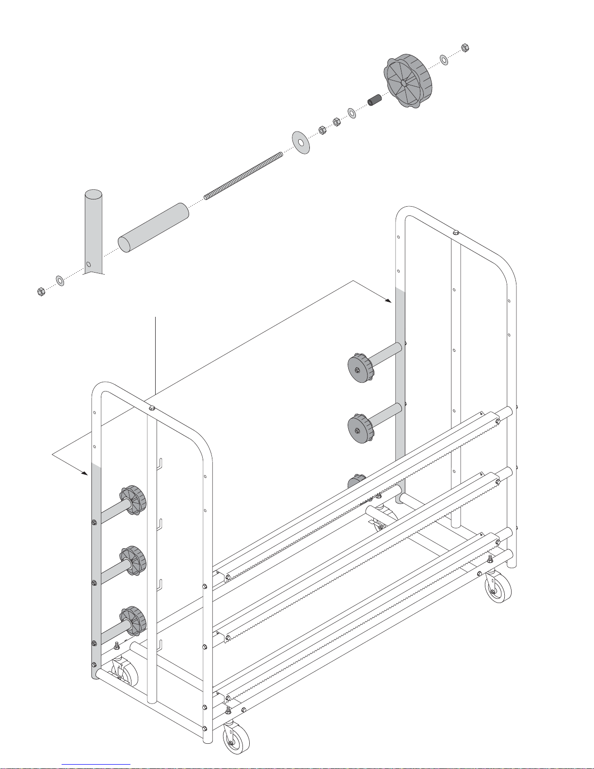
10678 ............ 1/4”-20 X 2” Knob .................................... 4
10677 ............ Paper Bar Washer................................ 12
10221 ............ Paper Bar Spring .................................... 5
10680 ............ Paper Bar Collar .................................. 12
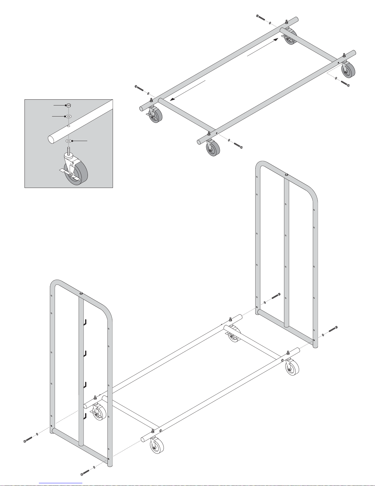
10755 ............ Swivel Caster.......................................... 2
10756 ............ Swivel Caster with Brake........................ 2
10757 ............ Paint Gun Rod ........................................ 2
PART#............ DESCRIPTION ...................... QUANTITY
11180.............. End Support Assembly (LEFT) .............. 1
12725 ............ End Support Assembly (RIGHT) ............ 1
10750 ............ Lower Horizontal Cross Member............ 2
10741 ............ Horizontal Support.................................. 2
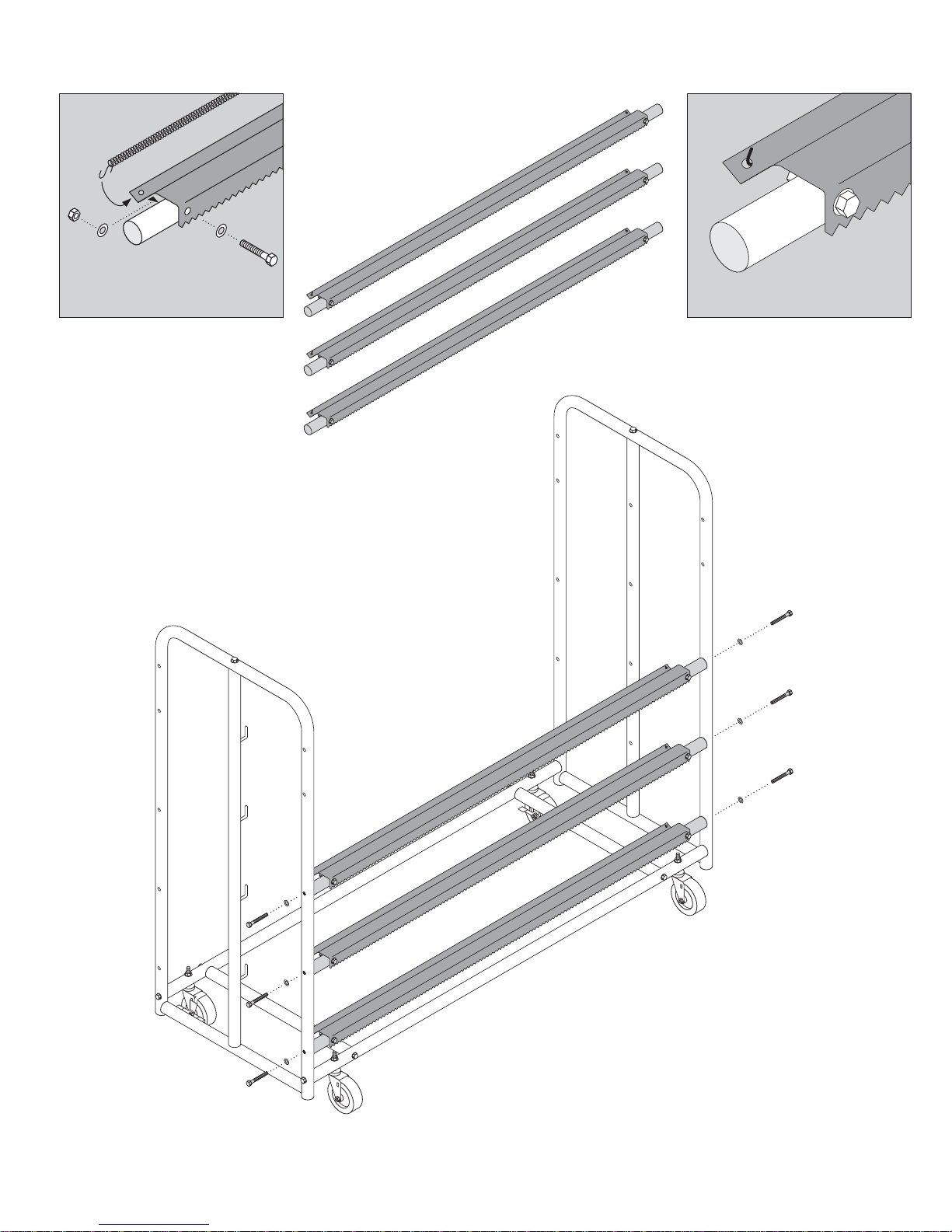
10748 ............ Cutter Bar Retainer ................................ 3
10749 ............ Paper Roll Bar ........................................ 4
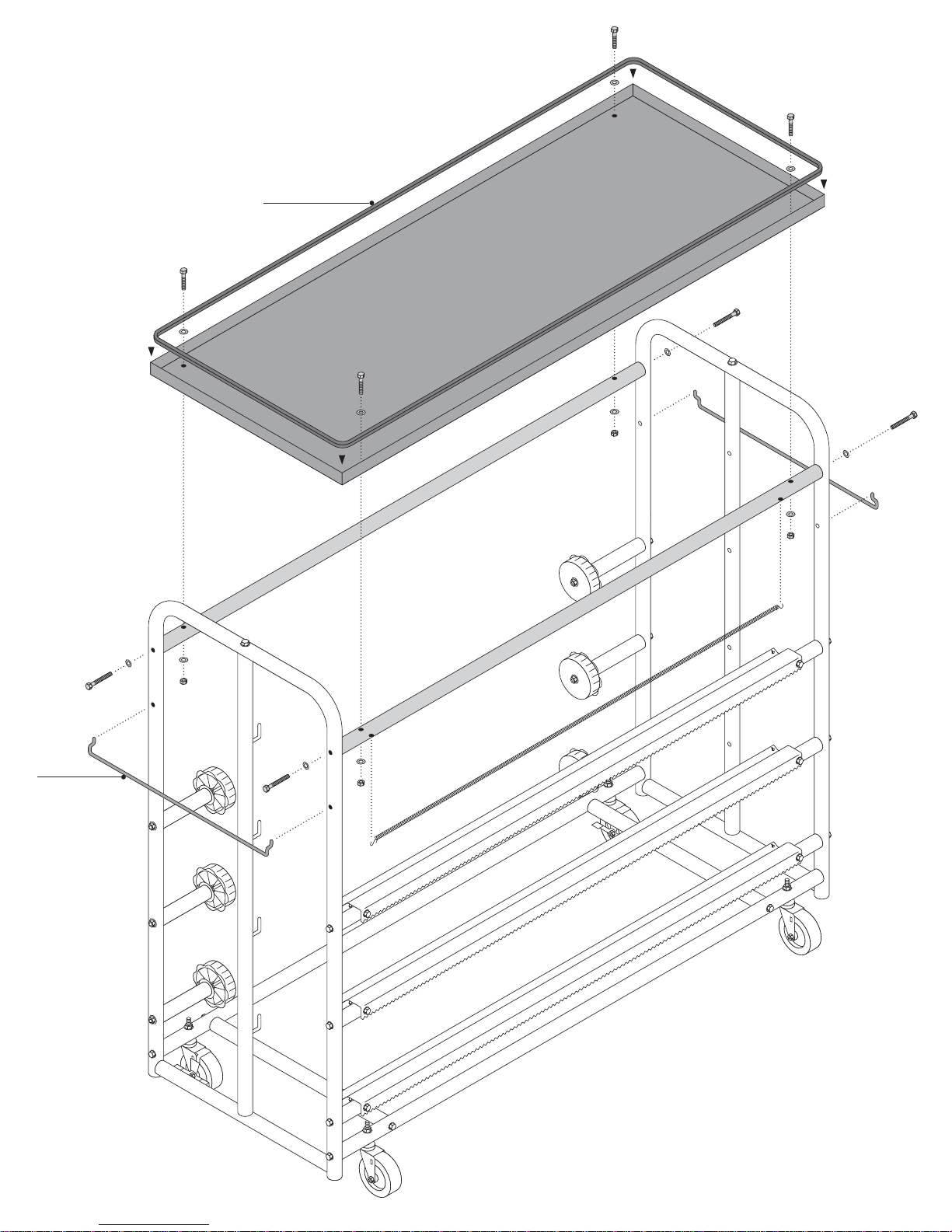
10747 ............ Tray Support .......................................... 2
10754 ............ Tray ........................................................ 1
10696 ............ Cutter Bar .............................................. 3
10689 ............ S-Hook.................................................... 8
10751 ............ Tape Spool Rod...................................... 6
10752 ............ Tape Spool Rod Cover............................ 6
10672 ............ Tape Spool.............................................. 6
10759 ............ Protective Edging (flex rubber) .... 11 Feet
10676 ............ 1/4”-20 X 11/2” Bolt ................................ 10
10675 ............ 1/4”-20 X 2” Bolt .................................... 18
10201 ............ 1/4”-20 Hex Nut...................................... 22
10694 ............ Extension Spring .................................... 4
Prep Station Part #78015
PARTS LIST
PAGE 1
225
STEP 2. Install left and right End Support
Assemblies using 1/4”-20 X 2” bolts and 1/4”
washers. NOTE: The left side has hooks.
NOTE: DO NOT overtighten hardware at this
stage. Leave hardware a little loose to aid in
the installation of upcoming components.
You will secure all hardware firmly when
assembly is complete at STEP 7.
Hex Nut
Washer
Washer
BACK
LEFT
(with hooks)
RIGHT
Locking Casters
Order of Nuts and Washers
for all wheel assemblies.
STEP 1. Assemble the wheel base
using 1/4”-20 X 2” bolts, 1/4” washers.
Next, assemble and attach the casters
using 3/8” washers and 3/8”-16 Hex Nuts.
Note the locations of all punched holes
in all tubing to ensure proper assembly.
NOTE: The 2 locking casters will be
installed at the BACK of the base.
PAGE 2
STEP 3. Assemble Cutter Bar Retainers using 1/4”-20 X 11/2” bolts and 1/4” washers. NOTE: All three Cutter Bar Retainers
are identical. Simply repeat the procedures illustrated below for each end of the assemblies.
225
Extension Spring “S”-Hooks
attach to the back side of the
Cutter Bar. A washer is used on
each side of the tubing for
added security. Repeat this
procedure for both sides of
each Cutter Bar Retainer.
Assembled view.
STEP 4. Starting at the bottom, install the
Cutter Bar Retainers using 1/4”-20 X 2” bolts
and 1/4” washers. Note the locations of all
punched holes in all tubing to ensure proper
assembly.
NOTE: Be sure that Cutter Bar teeth are
facing forward and pointing down as pictured.
THIRD
SECOND
FIRST
PAGE 3
STEP 5. Assemble and install the Tape Spool assemblies.
Following the diagram below, assemble all 6 identical Tape Spool
assemblies. NOTE: Be sure you are using the HEX Nuts and
LOCK Nuts in their correct locations. NOTE: DO NOT overtorque
the Acorn Nuts.
1/4”- 20 Acorn Nut
1/4” Flat Washer
1/4” Flat Washer
Tape Spool
Rod Cover
Tape Spool Insert (plastic)
Tape Spool
Rod - 7 1/8”
Tape Spool
1/4” X 11/4”
Fender Washer
1/4” - 20 HEX Nut
1/4” - 20 HEX Nut
1/4” - 20 LOCK Nut
1
/
4
”Flat Washer
Paper Bar
Retainer Posts
PAGE 4
STEP 6. Install Tray and supporting components. First, install
the supplied rubber Protective Edging in one continuous piece onto
the Tray edge and trim any excess. Next, install the 2 horizontal
Tray Support tubes (single hole side up) using 1/4”-20 X 2” bolts
and 1/4” washers. Lastly, secure the Tray to the horizontal Tray
Supports using 1/4”-20 X 11/2”bolts, 1/4” washers and 1/4”-20
Hex Nuts.
Protective
Edging
STEP 7. Install final Extension Spring
and Paint Gun Rods. Insert Extension
Spring “S” - Hooks into the remaining holes
UNDER the front horizontal Tray Support
tube. Next, install Paint Gun Rods into the
remaining holes on each side.
AT THIS POINT you may firmly tighten all
hardware but do not overtorque.
Extension Spring
Paint
Gun
Rod (2X)
PAGE 5
STEP 8. Roll assemblies. Below are examples of Paper Bar Roll
configurations. Follow the hardware order closely for maximum
performance. You may place the rolls in any order on the bottom
three hooks (next page). The top location is designated specifically
for plastic rolls only. Plastic rolls DO NOT use a Cutter Bar.
Washer
Washer
Washer
Washer
Spring
Spring
Collar
Push against roll
and tighten
Push against roll
and tighten
Collar
Collar
Collar
1” X 21/2”Washer is
used to apply force to
adjacent washers for
desired paper roll tension
while tightening Collars.
Push against roll
and tighten
Push against roll
and tighten Push against roll
and tighten
Push against roll
and tighten
PAGE 6
NOTE: The Collar wing nut is
offset. When Collar is used with
a Spring, the wing nut should
be closest to the Spring side.
250
STEP 9. Paper Bar roll installation. Surrounding tubing has been removed from the illustration only to clearly view the
installation area. Simply install the Paper Bar rolls from the back side. Be sure that the hole in the Paper Bar tube is aligned
to the “hook” side and secure the right side with the 1/4”-20 X 2” Knobs. The paper will then be fed BEHIND the Extension
Spring on the Cutter Bar Retainer to secure it in place for cutting.
Align paper rolls so that the
tape from the tape spools
covers half of the paper’s edge.
1/4”-20 X 2”
Knob
Install for paper to
come over the top
Feed paper between Extension Spring
and Cutter Bar to guide and secure paper
PAGE 7
250
PART NUMBER BREAKDOWN for ORDERABLE PARTS
10759
10696
10750
10747
10756
10741
10749
10754
NOTE: EVERY part is orderable.
If you do NOT see an item called out in
this illustration (such as specific nuts,
bolts, washers etc.) refer to the parts list
on Page 1 and contact the supplier where
you ordered your Prep Station.
11180
10752
10672
10757
12725
10748
10755
PAGE 8