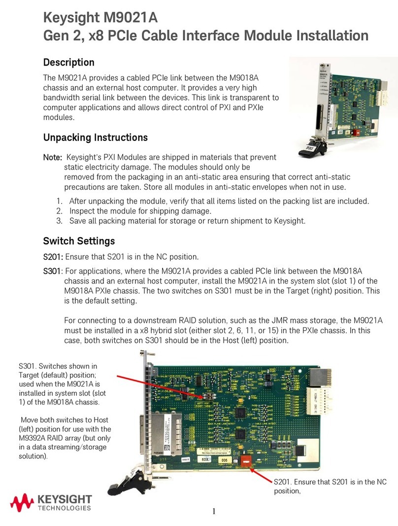
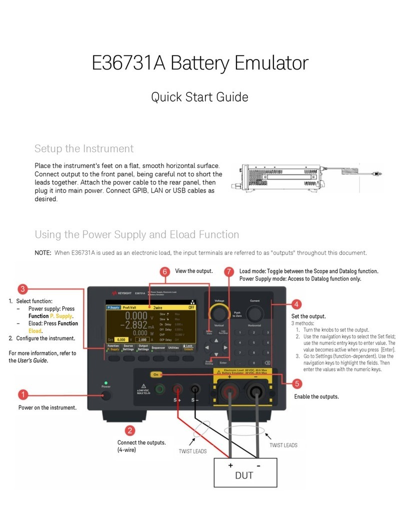
Keysight Technologies SL1200A Series User manual

Keysight SL1200A Series
Scienlab Regenerative
AC Emulator
Low Voltage & High Voltage
Operating
Instructions


Content
3/44
Scienlab Regenerative AC Emulator –Keysight SL1200A Series –Operating Instructions
Content
Notices.............................................................................................................................. 5
Safety and Regulatory Notices ........................................................................................ 8
User Information............................................................................................................. 12
1System Description ................................................................................................. 14
Intended Use............................................................................................................ 14
Foreseeable Misuse ................................................................................................. 14
Functional Description............................................................................................. 15
System Arrangement ............................................................................................... 16
Technical Data ......................................................................................................... 18
System data ........................................................................................................ 18
Electrical Specification ....................................................................................... 18
Measurement value acquisition.......................................................................... 19
Supplemental Characteristics ............................................................................ 19
Options ................................................................................................................ 20
DC Output ...................................................................................................... 20
Measurement value acquisition.......................................................................... 20
Supplemental Characteristics ............................................................................ 20
2Transport and Installation ....................................................................................... 21
Means of transportation .......................................................................................... 22
Before Installation.................................................................................................... 22
Transporting the System ......................................................................................... 22
Unpacking the system ............................................................................................. 22
Installing the system................................................................................................ 23
Disposing of the packaging material....................................................................... 23
3Connection and Assembly....................................................................................... 24
Electrical Installation ............................................................................................... 25
Connecting the mains supply (input) ................................................................. 25
Housing ground/functional earth....................................................................... 26
Connection of DUT (device under test) (output)..................................................... 27
Connection of AC mode...................................................................................... 27
Connecting load lines .................................................................................... 27
Connecting sense lines .................................................................................. 27
Additional DC mode connection (optional)........................................................ 27
Connecting load lines .................................................................................... 28
Connecting sense lines .................................................................................. 28
Using an emulator adapter with a Scienlab Charging Discovery System ........ 28
Connecting an emulator adapter .................................................................. 28
Parallel connection ............................................................................................. 29
Connecting signal and control lines........................................................................ 30

Content
4/44
Scienlab Regenerative AC Emulator –Keysight SL1200A Series –Operating Instructions
Communication interfaces.................................................................................. 30
Connecting higher-level safety technology ....................................................... 31
4Commissioning ........................................................................................................ 33
Procedure for switching on/off................................................................................ 34
Initial commissioning ............................................................................................... 35
Checking the relevant components.................................................................... 35
Performing initial commissioning ....................................................................... 35
Recommissioning..................................................................................................... 36
5Action in an Emergency .......................................................................................... 37
Control elements for switch-off............................................................................... 37
Switching off in an emergency ................................................................................ 38
6Troubleshooting and Fault Elimination................................................................... 39
Fault message via the PC software ......................................................................... 39
System cannot be switched on ............................................................................... 39
Tripping of the Surge Protection............................................................................. 39
7Servicing and Maintenance..................................................................................... 41
General Instructions for proper Maintenance......................................................... 41
Carrying out Maintenance Work ............................................................................. 42
Cleaning the system ........................................................................................... 42
8Decommissioning .................................................................................................... 43
Temporary Decommissioning.................................................................................. 43
Storage Conditions .................................................................................................. 43
Dismantling, Final Decommissioning...................................................................... 43

Notices
5/44
Scienlab Regenerative AC Emulator –Keysight SL1200A Series –Operating Instructions
Notices
Copyright Notice
© Keysight Technologies 2020 - 2021
No part of this manual may be reproduced in any form or by any means
(including electronic storage and retrieval, or translation into a foreign
language) without prior agreement and written consent from Keysight
Technologies, Inc. as governed by United States of America and interna-
tional copyright laws.
Edition
Edition 1.3, November 2021 (Original Operating Instructions)
Published by
Keysight Technologies Deutschland GmbH
Lise-Meitner-Allee 27
44801 Bochum, Germany
phone +49 234 41 75 78–0
mail info.sl@keysight.com
Technology Licenses
The hardware and / or software described in this document are furnished
under a license and may be used or copied only in accordance with the
terms of such license.
U.S. Government Rights
The Software is “commercial computer software,” as defined by Federal
Acquisition Regulation (“FAR”) 2.101. Pursuant to FAR 12.212 and 27.405-
3 and Department of Defense FAR Supplement (“DFARS”) 227.7202, the
U.S. government acquires commercial computer software under the same
terms by which the software is customarily provided to the public. Accord-
ingly, Keysight provides the Software to U.S. government customers under
its standard commercial license, which is embodied in its End User Li-
cense Agreement (EULA), a copy of which can be found at
www.keysight.com/find/sweula. The license set forth in the EULA repre-
sents the exclusive authority by which the U.S. government may use,
modify, distribute, or disclose the Software. The EULA and the license set
forth therein, does not require or permit, among other things, that
Keysight: (1) Furnish technical information related to commercial com-
puter software or commercial computer software documentation that is
not customarily provided to the public; or (2) Relinquish to, or otherwise
provide, the government rights in excess of these rights customarily pro-
vided to the public to use, modify, reproduce, release, perform, display, or
disclose commercial computer software or commercial computer software
documentation. No additional government requirements beyond those set
forth in the EULA shall apply, except to the extent that those terms, rights,

6/44
Scienlab Regenerative AC Emulator –Keysight SL1200A Series –Operating Instructions
Notices
or licenses are explicitly required from all providers of commercial com-
puter software pursuant to the FAR and the DFARS and are set forth spe-
cifically in writing elsewhere in the EULA. Keysight shall be under no obli-
gation to update, revise or otherwise modify the Software. With respect to
any technical data as defined by FAR 2.101, pursuant to FAR 12.211 and
27.404.2 and DFARS 227.7102, the U.S. government acquires no greater
than Limited Rights as defined in FAR 27.401 or DFAR 227.7103-5 (c), as
applicable in any technical data.
Warranty
THE MATERIAL CONTAINED IN THIS DOCUMENT IS PROVIDED “AS IS,”
AND IS SUBJECT TO BEING CHANGED, WITHOUT NOTICE, IN FUTURE
EDITIONS. FURTHER, TO THE MAXIMUM EXTENT PERMITTED BY APPLI-
CABLE LAW, KEYSIGHT DISCLAIMS ALL WARRANTIES, EITHER EXPRESS
OR IMPLIED, WITH REGARD TO THIS MANUAL AND ANY INFORMATION
CONTAINED HEREIN, INCLUDING BUT NOT LIMITED TO THE IMPLIED
WARRANTIES OF MERCHANTABILITY AND FITNESS FOR A PARTICULAR
PURPOSE. KEYSIGHT SHALL NOT BE LIABLE FOR ERRORS OR FOR INCI-
DENTAL OR CONSEQUENTIAL DAMAGES IN CONNECTION WITH THE
FURNISHING, USE, OR PERFORMANCE OF THIS DOCUMENT OR OF ANY
INFORMATION CONTAINED HEREIN. SHOULD KEYSIGHT AND THE USER
HAVE A SEPARATE WRITTEN AGREEMENT WITH WARRANTY TERMS
COVERING THE MATERIAL IN THIS DOCUMENT THAT CONFLICT WITH
THESE TERMS, THE WARRANTY TERMS IN THE SEPARATE AGREEMENT
SHALL CONTROL.

Notices
7/44
Scienlab Regenerative AC Emulator –Keysight SL1200A Series –Operating Instructions
Safety Information
A DANGER notice indicates a (extremely) hazardous situation which, if not
avoided, will result in death or serious injury.
Do not proceed beyond a DANGER notice until the indicated conditions are fully
understood and met.
A WARNING notice indicates a hazardous situation which, if not avoided, could
result in death or serious injury.
Do not proceed beyond a WARNING notice until the indicated conditions are fully
understood and met.
A CAUTION notice indicates a hazardous situation which, if not avoided, could
result in minor or moderate injury.
Do not proceed beyond a CAUTION notice until the indicated conditions are fully
understood and met.
A NOTICE indicates to pay attention to an operating procedure, practice, or the
like that, if not correctly performed or adhered to, could result in damage to the
product or loss of important data.
Do not proceed beyond a NOTICE until the indicated conditions are fully under-
stood and met.
A NOTE refers exclusively to application notes without any security relevance.
WARNING
CAUTION
NOTICE
DANGER
NOTE

Safety and Regulatory Notices
8/44
Scienlab Regenerative AC Emulator –Keysight SL1200A Series –Operating Instructions
Safety and Regulatory Notices
Using the system can cause danger and damage for life and limb of the
operators or third parties, to the system itself or to other material assets.
In addition to the manufacturer´s countermeasures, the operator must also
take appropriate countermeasures against danger due to residual energy.
The personnel must be briefed about these dangers and the necessary
countermeasures during instruction.
The following general safety precautions must be observed during all
phases of operation of this instrument. Failure to comply with these pre-
cautions or with specific warnings or instructions elsewhere in this manual
violates safety standards of design, manufacture, and intended use of the
instrument. Keysight Technologies assume no liability for the customer´s
failure to comply with these requirements. Please read the also the section
Intended Use.
Danger to life in case of misuse at the outputs.
The Scienlab Regenerative AC Emulator does not have its own insulation guard.
If the system emulates an electrical isolation against PE at the output, the lo-
cal installation regulations and guidelines must be observed.
This would be in the case of the emulation of an IT network in AC mode, or
generally in DC mode.
Danger to life due to high voltages.
Some components are still supplied with voltage after switching off (wiring color
orange).
Before installation and maintenance work, turn off and lock out all external
voltage supplies.
Only disconnect or establish electrical connections in a voltage-free condition.
Danger to life due to missing covers!
In case of misapplication, missing protective cover can lead to severe injury,
burns or death in the event of shock and arc flash.
Do not remove cover under load and not operate without cover in place.
After installation and maintenance work, the previously removed protective
cover must be replaced.
Depending on the set output voltage and current, the system sometimes releases
large amounts of energy at the output.
Touching the connection bars inside the system or the DUT terminals can occur
life-threatening body currents.
Never touch, connect, or disconnect the connecting lines to the DUT during
active operation.
Danger of arcing.
DANGER
DANGER
DANGER
DANGER

9/44
Scienlab Regenerative AC Emulator –Keysight SL1200A Series –Operating Instructions
Safety and Regulatory Notices
Residual voltage after switch-off.
In case of connected DUT, the output terminals can still carry voltages even after
switch-off of the system!
Measure the voltage at the outputs to ensure that they are voltage-free.
Danger to life due to charging or discharging batteries.
Batteries are sensitive to overloading/underloading and might explode or start
burning. This can lead to danger for life and limb.
Therefore, a battery must be monitored by a battery management system
(BMS).
Hearing protection due to noise exposure in the operating area!
Noise level < 85 dB(A) at a distance of 1 m from the front
It is recommended to wear hearing protection during operation.
Safety and Monitoring Devices
The system has monitoring devices that switch-off the system in case of
emergency. If additional systems are connected to the SL1200A Scienlab
Regenerative AC Emulator, it is recommended that the systems are inte-
grated into a higher-level safety device.
Main switch
•On the front side
•I ON: power supply switched on
•O OFF: power supply switched off, communication with the
system is maintained
•Trip: when emergency stop is triggered → system switches
off, main switch in position Trip
•Note: In the 0 OFF position, the main switch can be locked
using a padlock
Emergency stop push button
•On the front side
•Press: forces local emergency stop of the system
(Responds: see safety relay)
•Turn counterclockwise: unlocks
•Functional test of the emergency stop button: monthly
DANGER
NOTICE
DANGER

Safety and Regulatory Notices
10/44
Scienlab Regenerative AC Emulator –Keysight SL1200A Series –Operating Instructions
Key switch Test Release
•On the front side
•Used for enabling/disabling test
•OFF: test release withdrawn (output contactors and power
stage are blocked)
•ON: test release given, test may be started (e.g. acknowl-
edged by software)
Service switch/circuit breaker for motor protection
•Behind the front panel (detachable)
•Fuse for the circuit (logic path) tapped upstream of the main
switch
•O OFF: Circuit breaker has triggered → system is inactive; all
power and communication connections (logic path) are inac-
tive.
•I ON: Logic path active, system can be activated via main
switch
Surge protection
•Inside the Input Box on the rear side
•Responds in the event of overvoltage (e. g. due to lightning)
•Reaction: Feedback signal is detected → undervoltage moni-
toring reacts → the main switch cannot be activated (falls
back to position Trip)
•Consequence: Surge protection inlets must be changed by
KeysightCare, feedback contact is reset
Safety relay
•Inside the system
•Responds when the local emergency stop switch or external
input are triggered via the higher-level safety device (2-pin
each)
•AC supply of the power stages is interrupted, undervoltage
monitoring triggers, main switch on “Trip” → system is
switched off; power stage enable is withdrawn; 230 V auxil-
iary voltage and 24 V control voltage are maintained (logic
path)
Housing ground/functional earth
•On the rear side of the system
•Connection and coupling of housing ground
•Connection for EMC-compliant design
Display Soft Front Panel power stage
•On the front side
•Display is activated when power stage is active/in operation
•No settings needed

11/44
Scienlab Regenerative AC Emulator –Keysight SL1200A Series –Operating Instructions
Safety and Regulatory Notices
Signal lamp (default setting)
•On the top of the system
•red: failure signal
yellow: active signal
green: standby/ready signal
If the status of the configurable buses is
different, several lights can be lit simultane-
ously.
Safety Symbols
Protective earth-ground terminal
Housing ground
Danger, risk of electric shock
Caution, refer to accompanying description
Regulatory markings
The CE mark is a registered trademark of the European Community.
This CE mark shows that the product complies with all the relevant Eu-
ropean Legal Directives.
The UK Conformity Mark is a mark owned by the UK Government. Af-
fixing it to the product declares that all applicable directives and regu-
lations have been fully complied with.
This mark, also called the "cTUVus mark", is used to demonstrate
compliance with Canadian national standards issued by the Standards
Council of Canada (SCC) and U.S. national standards.
For model number SL1212A, SL1213A: This symbol is a South Korean
Class A EMC Declaration. This is a Class A instrument suitable for pro-
fessional use and in electromagnetic environment outside of the home.
This symbol indicates the product is recyclable.
The China RoHS mark indicates that toxic substance within the prod-
uct stay inside at least 40 years before expiring.
Contact address for questions to conformity of the product.
NOTE

User Information
12/44
Scienlab Regenerative AC Emulator –Keysight SL1200A Series –Operating Instructions
User Information
This Operating Instructions
describes how to transport, install, connect, commission, operate and
maintain the system,
provides important notes on safe and efficient handling of the system.
These Operating Instructions is part of the SL1200A Series Scienlab Re-
generative AC Emulator and should always be kept at the system´s place
of use.
The operating personal must read and understand the Operating Instructions and
all other safety instruction before using this system.
These Operating Instructions must be readily accessible and available operators
and maintenance personnel.
Applicable Documents
The following documents are also part of the system:
Declaration of conformity
User Manual SL1200A Regenerative AC Emulator Soft Front Panel
(SFP)
Getting Started SL1200A Scienlab Regenerative AC Emulator
Acceptance and calibration report
Action Instructions
Steps to be performed by the operating personnel are given as a num-
bered list. The order of the steps must be followed. The systems response
to the relevant steps are indicated by a check mark.
Example:
1Step 1
2Step 2
✓
System response to the steps.
Steps with no specific order are given as a bulleted list.
Example:
Point 1
Point 2
Links
Cross-references to other parts of this Operating Instructions or hyperlinks
to websites are shown in red.
Note for the Operator
If the SL1200A is integrated into an overall test bench with other systems,
the operator should carry out a risk assessment.
NOTICE

13/44
Scienlab Regenerative AC Emulator –Keysight SL1200A Series –Operating Instructions
User Information
Without prior connection to a higher-level safety system, misuse can result in life-
threatening injuries.
Keysight recommend first connecting the system to the higher-level safety and
emergency stop system of the test bench, before putting it into operation.
The Keysight emergency stop system in the control cabinet may not be
changed or adapted without the consent of Keysight.
Qualification of the Personnel
Personnel
KeysightCare
Electrically
trained persons
Trained persons
with specialist
training (me-
chanical/ elec-
trical engineer-
ing)
Activity
Transport
X
--
X
Connection and assembly
X
--
X
Commissioning
X
--
--
Operation
X
X
X
Maintenance
X
--
X
Replacement of system components
X
--
--
1
Troubleshooting
X
--
X
Disposal/recycling
X
--
X
Table 1: Qualification of personnel (X: permitted; --: not permitted)
Electrically trained persons:
Operator employees instructed and if necessary trained by KeysightCare
or an electrician in the tasks assigned to them and the possible dangers of
improper behavior as well as instructed in the necessary safety devices
and safety measures.
Trained persons with specialist training:
Operator employees instructed by KeysightCare, who accept specialist
and supervisory responsibility as electricians and are tasked with this
function by the company. In terms of adherence to the electrotechnical
safety specification, the responsible electrician must only receive instruc-
tion from other responsible electricians.
(Definition example acc.to DGUV Regulation 3, DIN VDE 0105-100, EN 50110)
Contact KeysightCare –Technical Support
Contact KeysightCare
Keysight Technologies Technical Support
www.keysight.com/find/keysightcare-contact
1
Unless otherwise contractually (e. g. in the context of a spare parts package), all mechanical/electrical instal-
lations in or on the system must always be coordinated with Keysight.
NOTICE

14/44
Scienlab Regenerative AC Emulator –Keysight SL1200A Series –Operating Instructions
1 System Description
1 System Description
Intended Use
The SL1200A Series Scienlab Regenerative AC Emulator is used for testing
the power electronics of charging systems and other components that can
be operated on any power grid, in particular
1-, 2- or 3-phase emulation of AC sources (Voltage Priority) up to a
voltage line-to-line 600 Vrms (low-voltage grid), or 1200 Vrms (high-volt-
age grid),
1-, 2- or 3-phase emulation of AC sink (Current Priority),
optional: emulation of a DC source/sink (Voltage/Current Priority) up to
500 V or 1000 V.
The SL1200A can be integrated in a comprehensive test solution for
photovoltaic inverters (PV), battery energy storage inverters, and other
types of grid-connected inverters,
energy storage systems, in conjunction with the Scienlab Charging Dis-
covery System (PHEV, EVSE, OBC).
The Scienlab Regenerative AC Emulator may only
be operated in within the current, voltage and power ranges indicated
in the Section Technical Data.
The system is built according to the applicable directives, the latest state
of the art, and recognized safety regulations.
The system must only be used in accordance with its intended uses. This is a
basic requirement for trouble-free and reliable operation. The system must be in
safe condition before it is commissioned.
Foreseeable Misuse
The following in particular shall be deemed to be improper use:
Any other use than that laid down in Intended Use and further de-
scribed in the operating instructions without the written consent of the
manufacturer,
Use, installation, operation, maintenance or repair of kind or manner
other than described and by unqualified personnel,
Use of non-approved, inappropriate accessories,
Non-compliance with safety and operating instructions, occupational
safety and accident prevention regulations or relevant statutory regula-
tions,
Failure to eliminate faults that may impair safety in a timely manner,
Use of spare and accessory parts other than the original,
Operation of the system with incomplete safety devices,
Operation of the system in explosive areas.
NOTICE

15/44
Scienlab Regenerative AC Emulator –Keysight SL1200A Series –Operating Instructions
System Description 1
Functional Description
The SL1200A serves as a regenerative, bi-directional, 3-phase AC
source/sink, with optional DC source/sink. The system can be parameter-
ized in voltage- or current-controlled mode (Voltage Priority or Current
Priority). The system was given a compact design with integrated measur-
ing and is available as Low-Voltage (600 V, model SL1201A –SL1203A) or
High Voltage (1200 V, model SL1212A –1213A) variant, depending on the
respective application.
The SL1200A consists of three (45 kVA) or six (90 kVA) power stages (RPS
–regenerative power system), there are two different types of power
stages, low voltage (600 V AC, optional 500 V DC) or high voltage
(1200 V AC, optional 1000 V DC). The power stages can be parametrized
and used individually or together with each other. Thus, various configura-
tions are possible.
In AC mode, the SL1200A is operated with a sinusoidal AC voltage output
and an adjustable basic frequency of 40 to 75 Hz. This enables the opera-
tor to supply 1-, 2- or 3-phase consumers, and test them in operation by
means of targeted error emulation (Voltage Priority). If the SL1200A is
configured in Current Priority mode, the power stage synchronizes with
the voltage measured at the terminals and regulates the specified (positive
or negative) current.
The following table shows examples for AC grid emulations.
Grid Form
Description Grid /
Example AC mode
Connection SL12xxA to DUT
PE reference
Neutral Pass Through
Contactor: closed
TN/TT grid
2
Without PE reference
Neutral Pass Through
Contactor: opened
IT grid
2
Table 2: Examples for emulated AC grids
Equipped with an optional DC mode, the SL1200A can be operated as a
Voltage Priority with different output voltages. If, for example, a charging
station is tested, the system can be used to emulate the HV battery in the
vehicle (Current Priority). If, instead, the vehicle with a battery is tested,
the SL1200A can emulate a DC charging station (Voltage Priority). If a
battery is connected to the SL1200A, the battery must be monitored by a
battery management system (BMS). The outputs at the DC mode are al-
ways electrically isolated against ground (PE).
The system features two separate current paths, the power path and the
logic path. The main switch uses the power path to disconnect the power
2
TN/TT grid: The generated phases have a potential reference to grounding (PE).
IT grid: The generated phases are electrically isolated from grounding (PE).

16/44
Scienlab Regenerative AC Emulator –Keysight SL1200A Series –Operating Instructions
1 System Description
stages and the grounding conductor interconnections from the mains. In
the event of an emergency stop, the main switch switches the output to a
safe condition.
Figure 1: Two current paths of SL1200A
When switching the system off via the main switch, some components
connected in the logic chain (e. g. measurement and control unit (MCU),
switch and safety relay) are not switched off by the supply disconnecting
device and continue to be supplied with voltage (lines marked orange) to
maintain communication between system and operating software, even in
the event of an emergency stop. The logic path can be switched off via the
service switch (service switch/circuit breaker for motor protection). This
switch is located on the front behind the detachable panel. When the logic
path is switched off, the power path cannot be switched on.
Via the customer interface, the system can be configured as either a 1- to
3-phase AC source/sink or a DC source/sink (DC optional, -SDC option).
Channel switchover between AC and DC operation may only be performed
in load-free state. AC and DC operation use separate terminal blocks (DC
terminals only on -SDC option) (see documentation Getting Started
Guide).
System Arrangement
The SL1200A consists of two rack variants with three or six power stages;
both rack variants are available as low-voltage and high-voltage. The low-
voltage variants SL1201A –SL1203A are designed with an output voltage
of up to 600 V, an output current of up to 125 A, and an output power of
up to 90 kVA. The high-voltage variants SL1212A –1213A, however, pro-
vide an output voltage of up to 1,200 V, an output current of up to 65 A,
and an output power of up to 90 kVA.
Communication to both a control computer and the parallel-connected
systems is ensured by Ethernet interfaces.

17/44
Scienlab Regenerative AC Emulator –Keysight SL1200A Series –Operating Instructions
System Description 1
Internal fans are responsible for cooling the interior of the system. These
are integrated into each individual power stage. Ventilation slots for dis-
charging the exhaust air are located at the rear of the system.
All essential connections are also located on the rear side of the system,
as shown in the following image.
Figure 2: System arrangement Scienlab Regenerative AC Emulator (left front side, right rear side)
(illustration similar)

18/44
Scienlab Regenerative AC Emulator –Keysight SL1200A Series –Operating Instructions
1 System Description
Technical Data
System data
System data
System designation
Scienlab Regenerative AC Emulator
Model number
SL1200A series
Model
Dimension (H x W x D)
Max. weight
SL1201A
AC power source, 30 kVA, 600 V, 63 A
1330 x 600 x 1100 mm
260 kg
SL1202A
AC power source, 45 kVA, 600 V, 63 A
1330 x 600 x 1100 mm
260 kg
SL1203A
AC power source, 90 kVA, 600 V, 125 A
1730 x 600 x 1100 mm
400 kg
SL1212A
AC power source, 45 kVA, 1200 V, 32 A
1330 x 600 x 1100 mm
260 kg
SL1213A
AC power source, 90 kVA, 1200 V, 65 A
1730 x 600 x 1100 mm
400 kg
Overvoltage category
III
Contamination level
2
Systems heat radiation
appr. 15% of output max. power
Protection class
IP20; Type 1 Enclosure (UL50E)
Operating conditions
Operating temperature
0°C … +40 °C
Storage temperature
-25 °C … +55 °C
Relative humidity
<95% (non-condensing)
Noise level
<85 dB(A) at a distance of 1 m from the front
Maximum operating altitude
2.000 m AMSL
Electrical Specification
AC Input Ratings
30 kVA power stage
45 kVA power stage
90 kVA power stage
Power supply
3P, N, PE, 380 … 480 V AC ±10%
Input frequency
50 / 60 Hz
Efficiency
85%
Power factor
0.99
Input power
34.5 kVA
51.75 kVA
103.5 kVA
Input current I
n
/
Mains supply pro-
tection provided
on site
@380 V grid
52.42 A / 63 A gG
78.63 A / 80 A gG
136.74 A / 160 A gG
@400 V grid
49.8 A / 63 A gG
74.69 A/ 80 A gG
129.90 A / 160 A gG
@480 V grid
41.5 A / 63 A gG
62.25 A/ 80 A gG
108.25 A / 125 A gG
Communication interface
To control PC, for parallel connec-
tion of various Scienlab Regenera-
tive AC Emulators
Ethernet LAN

19/44
Scienlab Regenerative AC Emulator –Keysight SL1200A Series –Operating Instructions
System Description 1
AC Output Ratings
SL1201A
SL1202A
SL1203A
SL1212A
SL1213A
Voltage range (rms)
0 … 600 V
L-L
AC resp. 0 … 346 V
L-N
0 … 1200 V
L-L
AC resp. 692 V
L-N
Output phase
L1, L2, L3, N, PE
~ Configuration
1-phase, 2-phase, 3-phase
1-phase@3xpower, connected outside in parallel
Output specifies cable length
10 m
Prog. Voltage resolution
0.1 V
rms
Prog. voltage accuracy
0.25% FS
Max. current (autoranging) rms
3
63 A
63 A
125 A
32 A
65 A
Current @ max. voltage
3
28.9 A
43.3 A
86.6 A
21.1 A
43.2 A
Max. current (parallel connection of
the load lines at the output) rms
3
189A
189 A
375 A
97.5 A
195 A
Max. power
3
±30 kVA
±45 kVA
±90 kVA
±45 kVA
±90 kVA
Max. power / per phase
±10 kVA
±15 kVA
±30 kVA
±15 kVA
±30 kVA
Fundamental frequency
40 … 75 Hz
Measurement value acquisition
Measurement value acquisition
(AC)
Resolution
Accuracy
Current measurement
0.1 Arms
±0.4 Arms ±0.2%
3
Voltage measurement
0.01 Vrms
±0.25 Vrms ±0.15%
Programmable voltage
0.1 Vrms
0.25% FS
Supplemental Characteristics
AC Output Rating
Resolution
Accuracy
Voltage Slew Rate
3V/µs open circuit
Progr. Frequency Slew Rate
±0.1%
Load regulation
0.25% FS
Phase Angle Setpoint
0.1 deg
1.5 deg
Progr. Frequency
0.01 Hz
±0.01%
Crest factor
up to 3.6
THD with linear load
0.25%
Leakage current
(for SL1201A/SL1202A)
14.6 mA (@ 16 A, 230 V, 750 Hz, 1 ph)
Measurement (AC)
Resolution
Accuracy
Frequency measurement
0.01 Hz
±0.04 Hz
Phase angle range 0 – 360 deg
0.5 deg
<±2 deg
AC Output peak current measure-
ment
±0.5 A ±0.5% of reading (<100 Hz)
3
Specification valid in single-phase mode

20/44
Scienlab Regenerative AC Emulator –Keysight SL1200A Series –Operating Instructions
1 System Description
Real Power Measurement
10 W
2.3% (working point Urms=230V, Irms=30A)
Apparent Power Measurement
10 VA
Reactive Power Measurement
10 VA
Power Factor Measurement
0.01
4.3% (working point Urms=230V,
Irms=30A cosPhi=0.95)
Output Energy Measurement
0.001 kWh
0.084% (working point Urms=230V, Irms=30A)
(SL1201A – SL1203A)
0.079% (working point Urms=230V, Irms=30A)
(SL1212A – SL1213A)
Options
DC Output
DC Output Ratings
SL1201A
SL1202A
SL1203A
SL1212A
SL1213A
Voltage
500
500
500
1000 V
1000 V
Current
4
180 A
180 A
360A
90 A
180 A
Power
4
40 kW
60 kW
120 kW
60 kW
120 kW
Output phase
DC+, DC-
Measurement value acquisition
Measurement value acquisition (DC)
Resolution
Accuracy
Current measurement
0.1 A
±18 mA ±0.03% (SL1201A, SL1202A, SL1213A)
4
±36 mA ±0.03% (SL1203A)
4
±9 mA ±0.03% (SL1212A)
4
Voltage measurement
0.1 V
±75 mV ±0.03% (SL1201A – SL1203A)
±150 mV ±0.03% (SL1212A – SL1213A)
Supplemental Characteristics
Measurement value acquisition (DC)
Current rise time (10% to 90%)
<2 ms
Voltage dynamic (10% to 90%)
500 V/ms
Load regulation
0.25% FS
4
Specification valid in single-phase mode
Table of contents
Other Keysight Technologies Computer Hardware manuals
Popular Computer Hardware manuals by other brands
Keyestudio
Keyestudio ESP32 manual
Thermaltake
Thermaltake Level 10 GT Battle Edition VN10008W2N user manual
ADLINK Technology
ADLINK Technology 6216-GL Series user manual
EK-Quantum
EK-Quantum Velocity2 D-RGB -LGA 1700 user guide

ekwb
ekwb EK-FC590 GTX Installation and mounting manuals
Advantech
Advantech AiMC-2000 user manual
AEB
AEB AC 26N user manual

Samsung
Samsung S5PC110 manual
ekwb
ekwb EK-FB ASRock X399 RGB Monoblock installation manual
Enterasys
Enterasys DFE-256MB-UGK installation instructions
Carotron
Carotron EP2020-000 instruction manual
Extron electronics
Extron electronics Scalable Multi-Graphic Videowall Processors MGP 464W... Specifications
