Kichler Lighting 37539 User manual

2
Français p. 15
Español p. 29
ITEM # 5024101, 5141833
MODEL # 37539, 37548
ROSEWOOD PLUG-IN WALL SCONCE
1
Questions, problems, missing parts? Before returning to your retailer, call our customer
service department at 800-554-6504, 8 a.m. - 4:30 p.m, EST, Monday - Friday.
kichler.com/customer-care/contact-us
ATTACH YOUR RECEIPT HERE
Serial Number Purchase Date
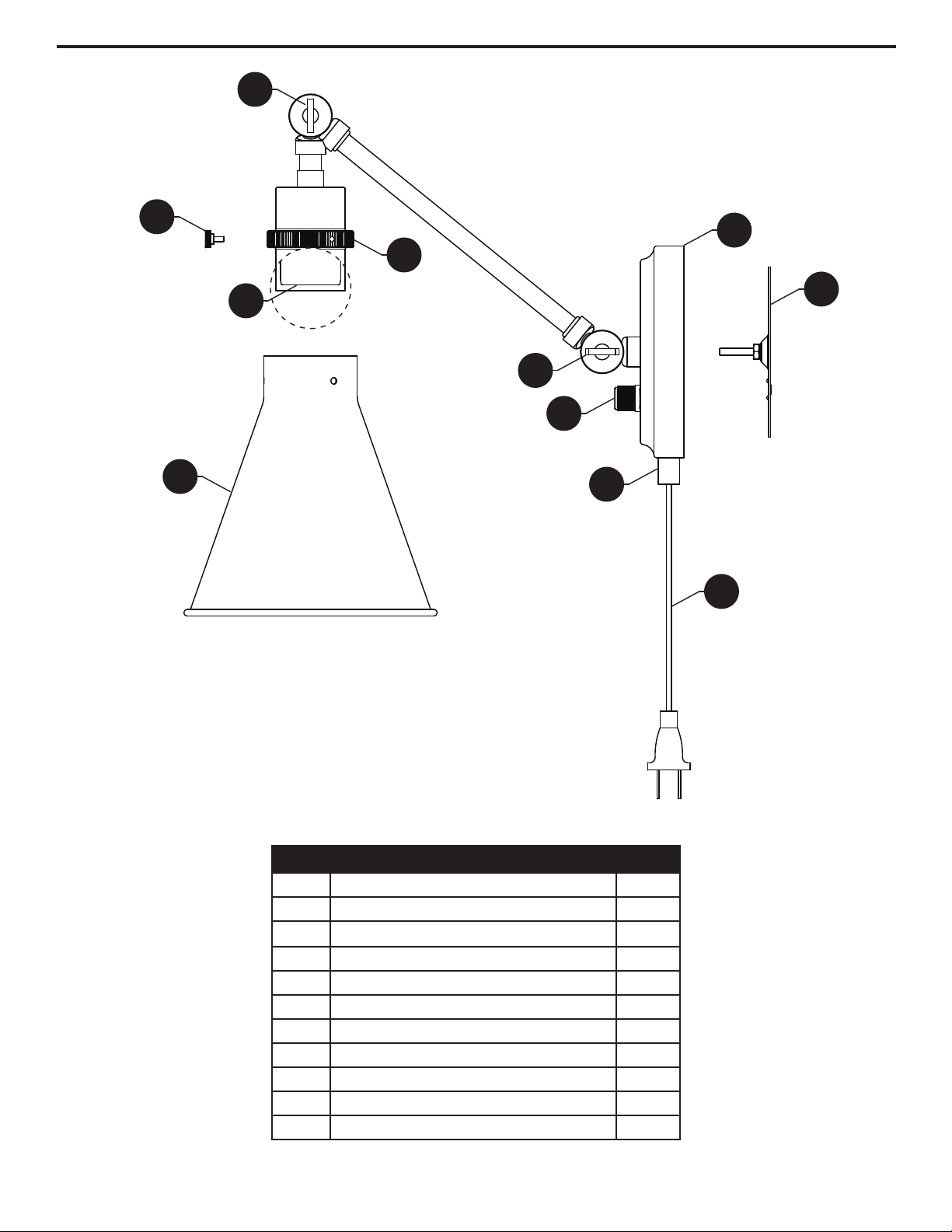
PACKAGE CONTENTS
2
1
D
H
C
A
G
A
Canopy
Mounting Bracket
Socket
Shade
Cord
Coupling
On/O Switch
Small Thumbscrew
Shade Adjustment Thumbscrew
Arm Adjustment Thumbscrew
Socket Cup
B
C
E
F
G
D
1
1
1
1
1
1
H 3
I 1
J 1
K 1
1
PART DESCRIPTION QTY.
1
PART DESCRIPTION QTY.
B
E
F
I
J
K
2 43
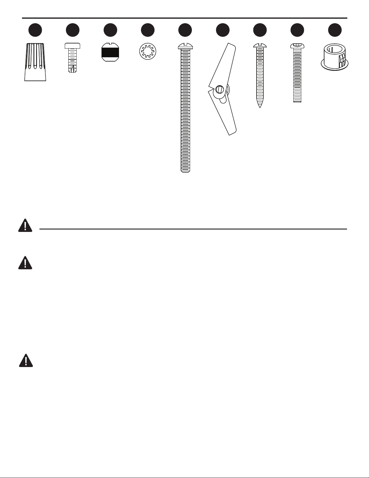
HARDWARE CONTENTS
Wire
Connector
AA BB CC DD
Qty: 3 Qty: 2
Short
Mounting
Screw
Lock
Washer
Qty: 2
Threaded
Knob
Qty: 2
SAFETY INFORMATION
Please read and understand this entire manual before attempting to assemble, operate or install
the product.
WARNING
• CAUTION – RISK OF SHOCK –
Disconnect Power at the main circuit breaker panel or main fusebox before starting and during
the installation.
• WARNING:
This fixture is intended for installation in accordance with the National Electrical Code (NEC)
and all local code specifications. If you are not familiar with code requirements, installation by a
certified electrician is recommended.
• Do not use bulbs with wattage greater than specified on this fixture.
• California Proposition 65
WARNING: This product can expose you to chemicals including lead, which is known to
the State of California to cause cancer, birth defects, or other reproductive harm.
For more information, go to http://www.P65Warnings.ca.gov
CAUTION
• If you have any doubts about how to install this lighting fixture, or if the fixture fails to operate
completely, please contact a licensed electrical contractor.
• All parts must be used as indicated in these instructions. Do not substitute any parts, leave
parts out, or use any parts that are worn out or broken. Failure to obey this instruction could
invalidate ETL listing and/or C.S.A. certification of this fixture.
Qty: 2
EE
Wall
Anchor
Qty: 2
FF
Qty: 2
GG
Qty: 2
HH
Long
Knob
Screw
Qty: 1
II
Hole
Cover
Wall Anchor
Mounting
Screw
Stud
Mounting
Screw
For Plug-In Mounting Assembly,
Go to Step 1a on Pg. 5
For Direct Wire Mounting Assembly,
Go to Step 1b on Pg. 8
NOTE: This model can be installed as a fixture that
plugs into a wall outlet, or a fixture that is directly wired
to a wall-mounted outlet box.

43
PREPARATION
Before beginning assembly of product, make sure all parts are present. Compare parts with package
contents list and hardware contents list. If any part is missing or damaged, do not attempt to
assemble the product.
Estimated assembly time: 30 minutes to 1 hour
Tools Required for Assembly (not included): Phillips screwdriver, flathead screwdriver, wire strippers,
electrical tape, ladder, safety glasses, drill, crescent wrench.
For Plug-In Mounting Assembly,
Go to Step 1a on Pg. 5
For Direct Wire Mounting Assembly,
Go to Step 1b on Pg. 8
NOTE: This model can be installed as a fixture that
plugs into a wall outlet, or a fixture that is directly wired
to a wall-mounted outlet box.
4 5 6
ASSEMBLY INSTRUCTIONS (PLUG-IN MOUNTING)
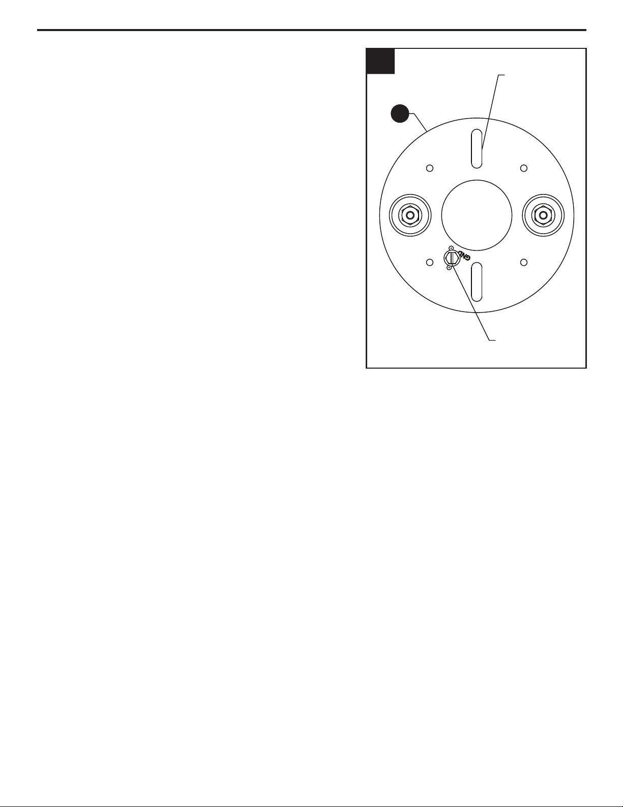
1a
1a.
Remove ground screw from mounting bracket
(B), and discard.
Find a suitable location on the wall to mount
your fixture (location should be within 6 feet of
an electrical outlet).
Using the mounting bracket (B) as a template,
place flat side of mounting bracket (B) flush
against wall with the mounting hardware slots
aligned vertically in the 12 and 6 o’clock position
as shown. Mark locations for the two (2)
mounting hardware holes, one in each
mounting hardware slot. Set mounting bracket
(B) aside.
If NOT mounting fixture on a stud,
Go to Step 2a on Pg. 6
If mounting fixture on a stud,
Go to Step 4a on Pg. 7
REMOVE AND
DISCARD
MOUNTING
HARDWARE
SLOT
For Plug-In Mounting Assembly,
Go to Step 1a on Pg. 5
For Direct Wire Mounting Assembly,
Go to Step 1b on Pg. 8
NOTE: This model can be installed as a fixture that
plugs into a wall outlet, or a fixture that is directly wired
to a wall-mounted outlet box.
B
x
x
5 6
ASSEMBLY INSTRUCTIONS (PLUG-IN MOUNTING)
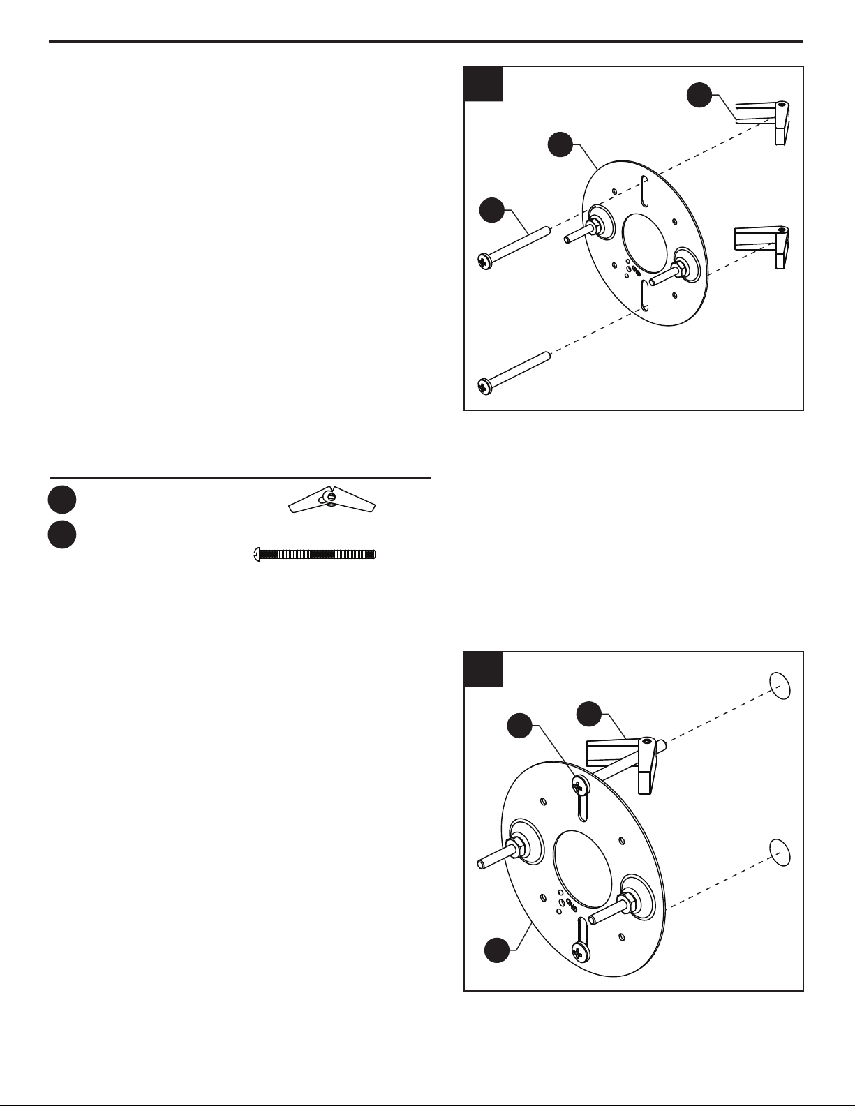
3a.
Push wall anchors (FF) through 11/16”
holes drilled in wall (wall anchor (FF) is
completely through wall when a "click" is
heard).
While holding mounting bracket (B) flat
against wall in its final mounting position,
gently pull wall anchor mounting screws
(EE) out and away from mounting bracket
(B) such that wall anchors (FF) are flush
against inside of wall surface, and tighten
wall anchor mounting screws (EE) to
secure mounting bracket (B) to wall
anchors (FF).
Go to Step 5a on Pg. 7
3a
B
7
2a
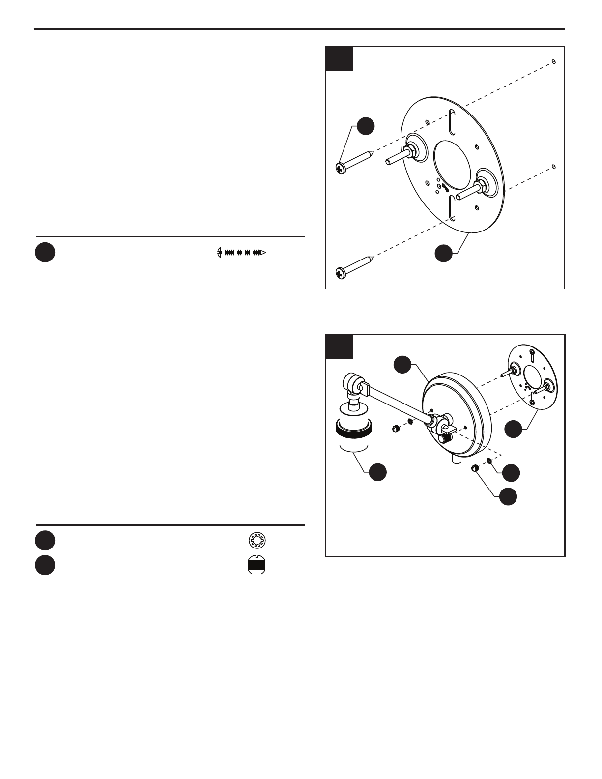
2a.
If NOT mounting fixture on a stud, drill
holes for mounting hardware where
marked in Step 1a. Using a 11/16" drill bit
(not included), drill a 11/16" hole at each
marked location for the wall anchors (FF)
and wall anchor mounting screws (EE).
Remove wall anchor mounting screws (EE)
from wall anchors (FF) and retain. Pass
threads of wall anchor mounting screws
(EE) through mounting hardware slots in
the mounting bracket (B), then thread
them back into wall anchors (FF) as
shown.
NOTE: Wall anchor mounting screws (EE)
should be threaded into wall anchors (FF)
such that 2-3 threads protrude through
wall anchor (FF).
EE
B
FF
Hardware Used
x 2Wall Anchor
FF
x 2
Wall Anchor
Mounting Screw
EE
EE FF
4a.
If mounting fixture on a stud, drill holes for
mounting hardware where marked in Step
1a. Using a 1/16" drill bit (not included), drill
a 1/16" pilot hole at each marked location
for the stud mounting screws (GG).
Hold mounting bracket (B) flat against wall
(with mounting hardware slots positioned
over 1/16” pilot holes) and screw stud
mounting screws (GG) into pilot holes.
Tighten stud mounting screws (GG) to
secure mounting bracket (B) to wall.
6
4a
B
GG
7
ASSEMBLY INSTRUCTIONS (PLUG-IN MOUNTING)
5a.
Pass canopy (A) over the screws
protruding from the mounting bracket (B)
and secure in place with lock washers (DD)
and threaded knobs (CC).
NOTE: Make sure all wires are inside of
canopy (A) and do not get pinched
between canopy (A) and mounting bracket
(B), or canopy (A) and wall.
NOTE: Fixture should be mounted with
socket (C) in the down position as shown.
Go to Step 1c on Pg. 12
8
Hardware Used
x 2Stud Mounting Screw
GG
Hardware Used
x 2Lock Washer
DD
x 2Threaded Knobs
CC
5a
DD
CC
B
A
C
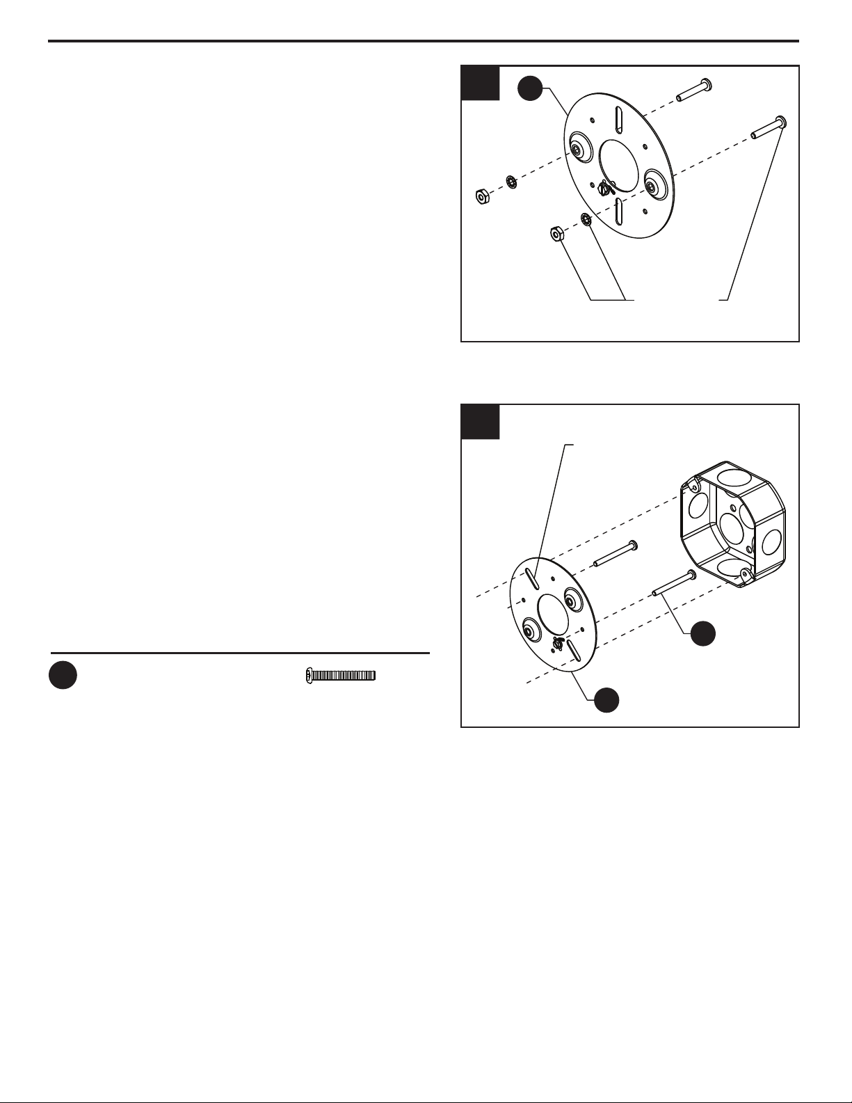
2b.
Orient the mounting bracket (B) such that
the mounting hardware slots align with
threaded holes in the outlet box (not
included) as shown.
Insert long knob screws (HH) through the
horizontally aligned threaded holes in the
mounting bracket (B) as shown, starting
from the outlet box side, with the threads
of the long knob screws (HH) protruding
outward.
7 8
ASSEMBLY INSTRUCTIONS (DIRECT WIRE MOUNTING)
1b.
Remove preassembled machine screws and
lock washers from mounting bracket (B) by
unscrewing hex nuts, and discard machine
screws, lock washers, and hex nuts.
1b B
2b
MOUNTING
HARDWARE
SLOT
REMOVE
AND DISCARD
B
HH
9
Hardware Used
x 2Long Knob Screw
HH

3b.
With the long knob screws (HH)
protruding outward, connect the
mounting bracket (B) to the outlet box
using short mounting screws (BB).
8
HH
9
ASSEMBLY INSTRUCTIONS (DIRECT WIRE MOUNTING)
3b
4b.
Pull up an additional length of cord (E) into
canopy (A). Cut cord (E) approximately (8)
inches from center of canopy (A). Discard
the remaining length of cord (E) attached
to the plug.
CAUTION: Ensure cord is NOT plugged
into electrical outlet when cutting the
cord.
4b
A
BB
B
E
10
Hardware Used
x 2Short Mounting Screws
BB
9 10
ASSEMBLY INSTRUCTIONS (DIRECT WIRE MOUNTING)
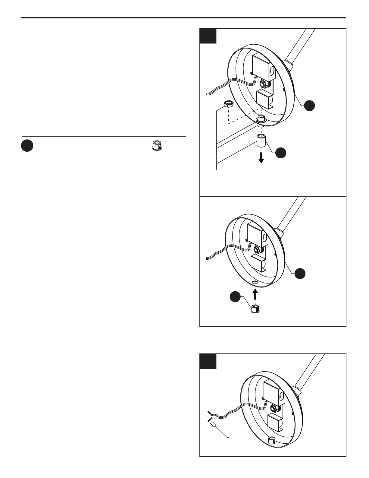
5b.
Remove coupling (F) from the bottom of
canopy (A) by unscrewing the hex nut
from the short threaded pipe protruding
into the canopy (A). Discard the coupling
(F), short threaded pipe, hex nut, and lock
washer.
Insert hole cover (II) into hole from the
outside of canopy (A) such that bottom
of hole cover (II) is flush with bottom of
canopy (A) when installed.
5b
6b.
Split the end of the cord and strip ends of
each wire 1/2" (13mm).
6b
0.5"
[13mm]
11
REMOVE AND
DISCARD
Hardware Used
x 1Hole Cover
II
A
F
A
II
This manual suits for next models
3
Table of contents
Languages:
Other Kichler Lighting Home Lighting manuals


