manuals.online logo
Brands
  1. Home
  2. •
  3. Brands
  4. •
  5. Kicker
  6. •
  7. Subwoofer
  8. •
  9. Kicker PRAMCQ09 User manual

Kicker PRAMCQ09 User manual

Other Kicker Subwoofer manuals

Kicker SubStation PES10C User manual

Kicker

Kicker SubStation PES10C User manual

Kicker X15c User manual

Kicker

Kicker X15c User manual

Kicker XPL C-SERIES User manual

Kicker

Kicker XPL C-SERIES User manual

Kicker TCVT10 User manual

Kicker

Kicker TCVT10 User manual

Kicker Comp DC12 User manual

Kicker

Kicker Comp DC12 User manual

Kicker PWRA215 User manual

Kicker

Kicker PWRA215 User manual

Kicker KM10 User manual

Kicker

Kicker KM10 User manual

Kicker subwoofer ES104 User manual

Kicker

Kicker subwoofer ES104 User manual

Kicker CompS10 User manual

Kicker

Kicker CompS10 User manual

Kicker Comp DC12 User manual

Kicker

Kicker Comp DC12 User manual

Kicker SOLO-BARIC SERIES User manual

Kicker

Kicker SOLO-BARIC SERIES User manual

Kicker SoloX L7X Series User manual

Kicker

Kicker SoloX L7X Series User manual

Kicker SoloX 49L7X151 User manual

Kicker

Kicker SoloX 49L7X151 User manual

Kicker KMW10 User manual

Kicker

Kicker KMW10 User manual

Kicker PWRA2P07 User manual

Kicker

Kicker PWRA2P07 User manual

Kicker Comp VR C18d User manual

Kicker

Kicker Comp VR C18d User manual

Kicker SOLO-BARIC L7S12 User manual

Kicker

Kicker SOLO-BARIC L7S12 User manual

Kicker CompVR C8vr User manual

Kicker

Kicker CompVR C8vr User manual

Kicker CompVX Series User manual

Kicker

Kicker CompVX Series User manual

Kicker SRAMCQ09 User manual

Kicker

Kicker SRAMCQ09 User manual

Kicker CompVT CVT12 User manual

Kicker

Kicker CompVT CVT12 User manual

Kicker COMPVT CVT124 User manual

Kicker

Kicker COMPVT CVT124 User manual

Kicker PSON13 User manual

Kicker

Kicker PSON13 User manual

Kicker ZX350.2 User manual

Kicker

Kicker ZX350.2 User manual

Popular Subwoofer manuals by other brands

Extron electronics SF 8CT SUB user guide

Extron electronics

Extron electronics SF 8CT SUB user guide

SVS PB-4000 quick start guide

SVS

SVS PB-4000 quick start guide

Pioneer S-DVR9SW Service manual

Pioneer

Pioneer S-DVR9SW Service manual

Yamaha YST-SW515 Service manual

Yamaha

Yamaha YST-SW515 Service manual

Velodyne SPL-800 ULTRA - REV B datasheet

Velodyne

Velodyne SPL-800 ULTRA - REV B datasheet

Teufel US 2110/1 SW operating instructions

Teufel

Teufel US 2110/1 SW operating instructions

Wet Sounds SS-65 user manual

Wet Sounds

Wet Sounds SS-65 user manual

Pyle PLQB10 Specifications

Pyle

Pyle PLQB10 Specifications

Sony XS-L1536 Product guide

Sony

Sony XS-L1536 Product guide

Sony XS-AW8 operating instructions

Sony

Sony XS-AW8 operating instructions

B&C Speakers 15 HPL 76W Specifications

B&C Speakers

B&C Speakers 15 HPL 76W Specifications

Velodyne DD-18+ Specifications

Velodyne

Velodyne DD-18+ Specifications

Sonance Cinema Series SUB 10-150 Specifications

Sonance

Sonance Cinema Series SUB 10-150 Specifications

Hifonics HW-12 Owners & installation manual

Hifonics

Hifonics HW-12 Owners & installation manual

Yamaha 64263 owner's manual

Yamaha

Yamaha 64263 owner's manual

Magnat Audio ADR 130 BP user manual

Magnat Audio

Magnat Audio ADR 130 BP user manual

Technics SB-AS500 Operaing instructions

Technics

Technics SB-AS500 Operaing instructions

Lyngdorf BW-2 owner's manual

Lyngdorf

Lyngdorf BW-2 owner's manual

manuals.online logo
manuals.online logoBrands
  • About & Mission
  • Contact us
  • Privacy Policy
  • Terms and Conditions

Copyright 2025 Manuals.Online. All Rights Reserved.

1
PRAMCQ09
Designed for 2009–2012 Dodge®Ram vehicles
©2012 Stillwater Designs
PRAMCQ09-A3-20140729
Subwoofer Assembly
Wire Ties x6
25A Fuse
Power Harness
Overlay Harness
T-Taps x2
Amplifier
Seat bolt
2
Amplifier Assembly
Overlay Harness
Power Harness
7mm Screws x3
25A Fuse
Wire Ties x6
3
1. Disconnect negative battery cable
2. Pull the rubber liner out of the storage tray on the dash and remove two Torx®T-20
screws. Fig. 1
3. Using a panel removal tool pry out on the plastic trim panel of the 110V AC plug and re-
move it, if so equipped. Fig. 2
4. Remove the Torx®T-20 behind the plastic trim panel removed in step 2, if so equipped.
Fig. 3
If the vehicle does not have a center console skip to step 9.
5. Using a panel removal tool, carefully pry up on the trim ring around the shifter and remove.
Fig. 4
6. Pull up on the front edge of the rubber liner in the storage area under the HVAC cotrols
and remove. Fig 5
7. Remove the two Phillips screws under the rubber liner removed in step 6. Fig. 6
Fig. 1
Fig. 2
Fig. 3
Fig. 4
Remember to place your warranty card in the glove box for future use.
4
8. Using a panel removal tool gently pry up on the panel surrounding the shifter housing and
remove. Fig. 7
9. Using a panel removal tool gently pry out on the radio trim bezel. Fig. 8
10. Unplug the factory wiring on the radio trim bezel and remove.
11. Remove the four 7mm screws securing the radio.
12. Pull the radio from the dash and disconnect the wiring. Disconnect the antenna cable
by pulling the locking antenna connector away from the radio. Caution: Pulling the antenna
cable straight out of the radio without pulling on the locking antenna connector could
damage the cable or radio.
Fig. 5
Fig. 6
Fig. 7
Fig. 8
5
13. Loosen and remove the nut on the positive battery accessory lug. Fig. 9
14. Connect the ring terminal of both power harnesses to the lug and retighten the nut.
Torque to 14Nm.
15. Route the wires toward the rubber grommet on the fire wall where the factory wiring
harness passes through.
16. Make a small hole in the grommet using a razor knife and push the power wires through
the rubber grommet. Pull the wires through from the inside until the protective loom touches
the grommet underneath the hood. (Approximately 15 inches on the inside of the vehicle.)
Fig. 10
17. Install the supplied three pin connector by inserting the terminals on the end of the power
wire into the back of the connector until they click and lock. (Any pin can go in any location.)
Fig. 11
18. Install the supplied two pin connector by inserting the terminal on the end of the red
power wire into the back of the black connector until it clicks and locks.
19. Remove the two 7mm screws securing the plastic panel below the steering column.
Gently pull out on the bottom of the panel to release the plastic fasteners. Leave the hood
release lever and wiring harness connected and just let the panel hang below the dash. Fig.
12
Fig. 9
Fig. 10
Fig. 11
Fig. 12
6
20. Plug the amplifier harness into the amplifier and install the amplifier in the dash by sliding
the two ¼” bolts on the amp bracket into the slotted holes on the dash support brace by the
factory grounding point and then lining up the hole on the top of the bracket with the hole in
the dash frame. Insert the supplied 7mm screw and tighten. Fig. 13
21. Then tighten the two bolts that were aligned in the slotted holes Fig. 14
22. Remove the factory 10mm bolt from the factory grounding point next to the amplifier and
connect the black ground wire for both the subwoofer and amplifier harness. Torque to 5Nm.
Fig. 15
23. Route the amp harness to the radio opening
24. Connect the male radio harness connecter to the female connecter of the amp harness
and tuck this connection out of the way to avoid interference with radio during reinstallation.
Fig. 16
25. You can now connect the radio to the amp harness and reconnect the antennae wire
and reinstall the radio.
26. Plug the power wire connector on the amplifier harness to the connector you installed on
the wires coming from the under the hood.
27. Connect the subwoofer output spade terminals of the amplifier harness to the corre-
sponding spade terminals of the subwoofer harness.
Fig. 15
Fig. 16
Fig. 14
Fig. 13
7
Subwoofer Harness Routing
28. Route the harness down the kick panel and along the bottom of the front door jam.
Route the 10 pin connector under the front seat and out of the existing hole. Fig 17
29. Remove the two 8mm bolts holding the bracket for the seat wiring. Mount the amplifier/
bracket assembly as shown in Fig 18
30. Connect the ten pin connector of the harness to the amplifier. Slide the red locking tab
over to prevent the connectors from accidentally coming disconnected.
31. If the vehicle is equipped with the storage cover under the rear seat, the driver’s side
cover will need to be removed to allow the subwoofer to install. To remove the storage cov-
er, remove the four 18mm bolts securing the drivers side rear seat and carefully lift the seat
out. Fig 19
32. Using a panel removal tool remove the plastic cover on the side of the seat. Fig. 20
Fig. 17
Fig. 18
Fig. 19 Fig. 20
8
33. Remove the 13mm and 10mm bolt on both sides of the bottom of the rear seat removed
in step 26 and remove the storage cover. Fig. 21
34. Reinstall the seat and the back two 18mm bolts securing the seat. Tighten to 30ft/lbs.
35. Remove the Torx®T30 securing the front latch of the storage cover and remove latch.
Fig. 22
36. For vehicles equipped with one piece rear bench seats remove the 18mm bolt securing
the driver’s (left) side of the seat to the floor.
37. For one piece rear bench seat you will also need to find threaded nut insert in the floor
pan concealed by the carpet flap. Fig. 23
38. Set the enclosure in place and reinstall seat bolts (a bolt is supplied for one piece bench
seats) and tighten. Torque to 30 ft/lbs. Fig. 24
Fig. 21
Fig. 22
Fig. 23
Fig. 24
9
39. Route the harness along the bottom of the front and rear door jam. Route the harness
behind the plastic sill plate and under the driver’s side rear, outermost seat bracket. Fig. 25
40. Connect the four pin plug of the subwoofer harness to the subwoofer enclosure. Slide
the red locking tab over to prevent the connectors from accidentally coming disconnected.
41. If the vehicle is equipped with a factory subwoofer it must be disconnected for the sys-
tem to operate properly.
42. Reinstall all previously removed parts in reverse order making sure not to pinch any wires
along the way during the re-installation process. Failure to do so could result in an electrical
short in the vehicle.
43. Install the supplied fuses in the fuse holders under the hood.
44. Reconnect the negative battery cable. Torque to 5Nm.
Fig. 25
10
Troubleshooting the Kicker Integrated Systems
If you experience a problem once the Subwoofer is installed, use this guide to locate the trouble.
The radio is working, but the Subwoofer is not working:
• Check the battery voltage to make sure it is not discharged below 11 volts.
• Check the negative battery cable to see if it has been securely tightened back on the battery.
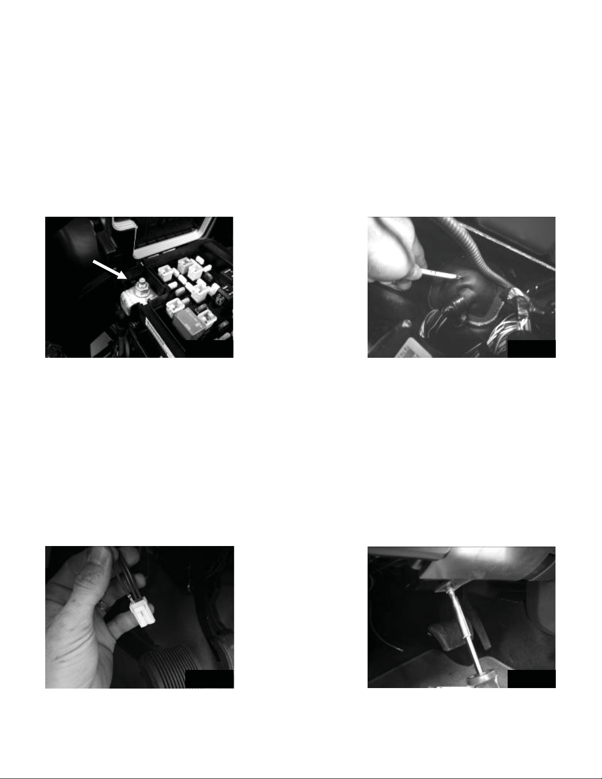
• Check the inline fuse located near the battery to make sure it is plugged in completely, and not blown.
• Check the inline +12Volt power-connector near the firewall to make sure it is plugged in securely.
• Check the inline connectors near the subwoofer enclosure to make sure they are plugged securely.
• Check the ground wire connection to make sure it is tightly secured to the proper ground in the vehicle.
• Check the audio input signal connection to make sure it is secure and connected to the proper wiring.
• Test with different music in case there is no low frequency audio in the initial sound check.
There is a buzz or rattle noise that accompanies the low frequency element of the music:
• Check for a connector or any other object that could be very near the enclosure.
• Check the subwoofer enclosure mounting brackets to make sure they are secure.
There is a problem with the multi-channel stereo amplifier:
• Check the battery voltage to make sure it is not discharged below 11 volts.
• Check the negative battery cable to see if it has been securely tightened back on the battery.
• Check the inline fuse located near the battery to see if it is plugged in completely and not blown.
• Check the multi-pin connecters at the back of the radio and at the amplifier chassis to make sure they
are plugged all the way in.
• Check the ground wire connection to make sure it is tightly secured to the proper ground in the vehicle.