- 2 -
GENERAL MENU NAVIGATION
General menu navigation rules include the following keypad
instructions:
1. Press the <>and <>buttons to navigate the menu
levels.
2. Press <E> (Enter) to enter any sub-menu from any
higher level.
3. Press the <>button to return to a previous menu.
MAIN MENU LEVEL SELECTIONS
To access Main Menu selections, press the <>and <>
buttons until the LCD display shows the desired selection, then
press <E>. There are four Main Menu selections:
•Single Addressing - Set an address for a single device at
a time.
•Sequential Addressing - Set an address range (with a
start address and end address), and give each device a
unique address within that range. Program multiple
devices quickly, and reduce the possibility of setting dupli-
cate addresses.
•Alarm Test - Test the alarm initiating responses of initiating
devices. A device that fails the Alarm Test should not be
installed.
•Options - Adjust LCD settings; show current firmware ver-
sion; adjust the Power-Off timer.
CONNECTING TO VARIOUS SMARTONE DEVICES
(The power may be ON or OFF when connecting the various
SmartOne devices.)
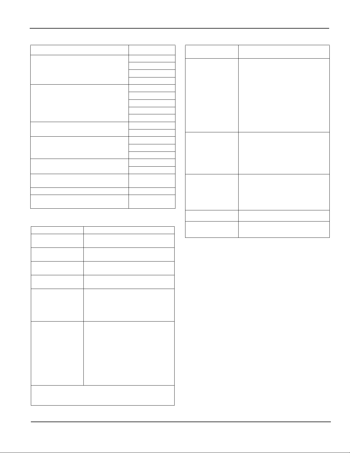
Smoke/Heat Detectors
Snap the detector into the detector base, orient the index
marker on the device to the five o’clock position, then rotate
clockwise.
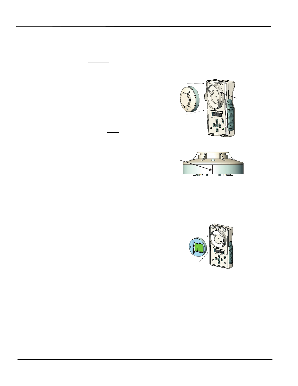
Addressable Input/Addressable Output Modules
1. Connect the AI/AO Module Adaptor to the detector base,
orient the index marker on the device to the five o’clock
position, then rotate clockwise.
2. Insert the AI or AO module so that the terminal block faces
left. Tilt the module into the recess of the adaptor so that
the terminal block screws make contact with the spring-
loaded probes; then snap the back of the module into the
right half of the recess.
Other Devices
Plug the SLC Interface Adaptor jack into the Programmer Con-
nector marked “SLC OUT.” Locate terminal blocks on device
labeled “SLC” or “PC Line.” Connect one SLC Interface Adaptor
wire to Terminal “A” on the device, and the other wire to Termi-
nal “B.”
Detector
Base
Smoke
Detector