manuals.online logo
Brands
  1. Home
  2. •
  3. Brands
  4. •
  5. Kidde
  6. •
  7. Speakers
  8. •
  9. Kidde Genesis LED EG4S Series Assembly instructions

Kidde Genesis LED EG4S Series Assembly instructions

© 2020 Carrier 1 / 4 P/N 3102667-EN • REV 002 • ISS 31AUG20
Genesis LED EG4S Series
Wall Speaker-Strobe
Installation Sheet
Description
Genesis LED EG4S speakers and EG4SV speaker-strobes are wall-
mounted plug-in fire alarm notification appliances designed for indoor
dry applications with 25 or 70 VRMS distributed speaker systems. See
the tables below for a list of models.
Table 1: EG4S speaker models
Catalog number
Description
E
G4SRF Speaker, wall, red, FIRE
E
G4SRN Speaker, wall, red, no marking
E
G4SWA Speaker, wall, white, ALERT
E
G4SWF Speaker, wall, white, FIRE
E
G4SWN Speaker, wall, white, no marking
Table 2: EG4SV speaker-strobe models
Catalog number
Description
E
G4SVRF Speaker-strobe, wall, red, FIRE
E
G4SVRN Speaker-strobe, wall, red, no marking
E
G4SVWA Speaker-strobe, wall, white, ALERT
E
G4SVWF Speaker-strobe, wall, white, FIRE
EG4SVWN
Speaker-strobe, wall, white, no marking
Genesis LED EG4S Series speakers and speaker-strobes feature:
• Field-configurable speaker and strobe outputs. See Figure 2 and
Figure 3.
• Enhanced synchronization circuitry to comply with the latest
requirements of UL 1638 and CAN/ULC-S526.
• Input wiring test points on the front of the appliance when the
cover is removed.
• Speakers that are approved for low frequency sounder
applications when used with compatible tone file and systems.
Note: Synchronized operation requires a separately installed
synchronization device. See the control unit or power supply
compatibility list for compatible synchronization devices.
Configuration
Caution: Equipment damage hazard. Using excessive force when
removing the appliance cover may damage the cover and prevent it
from latching in place.
To configure the notification appliance:
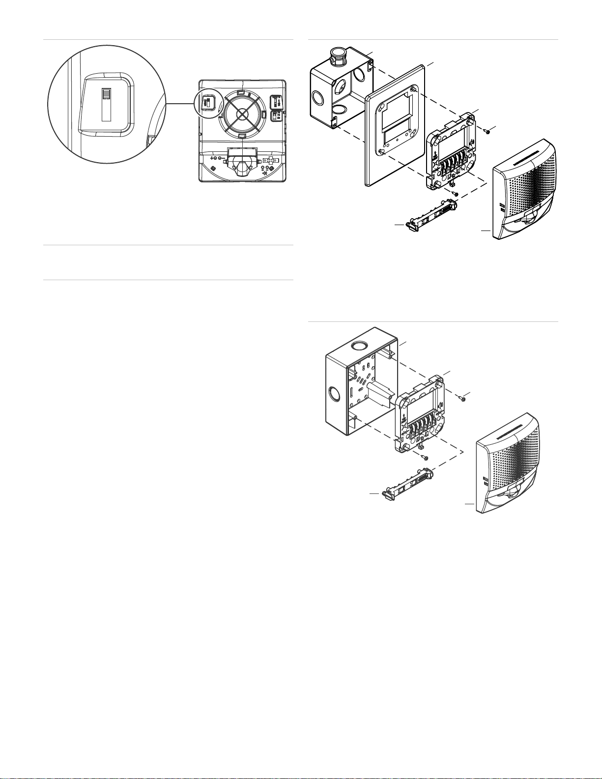
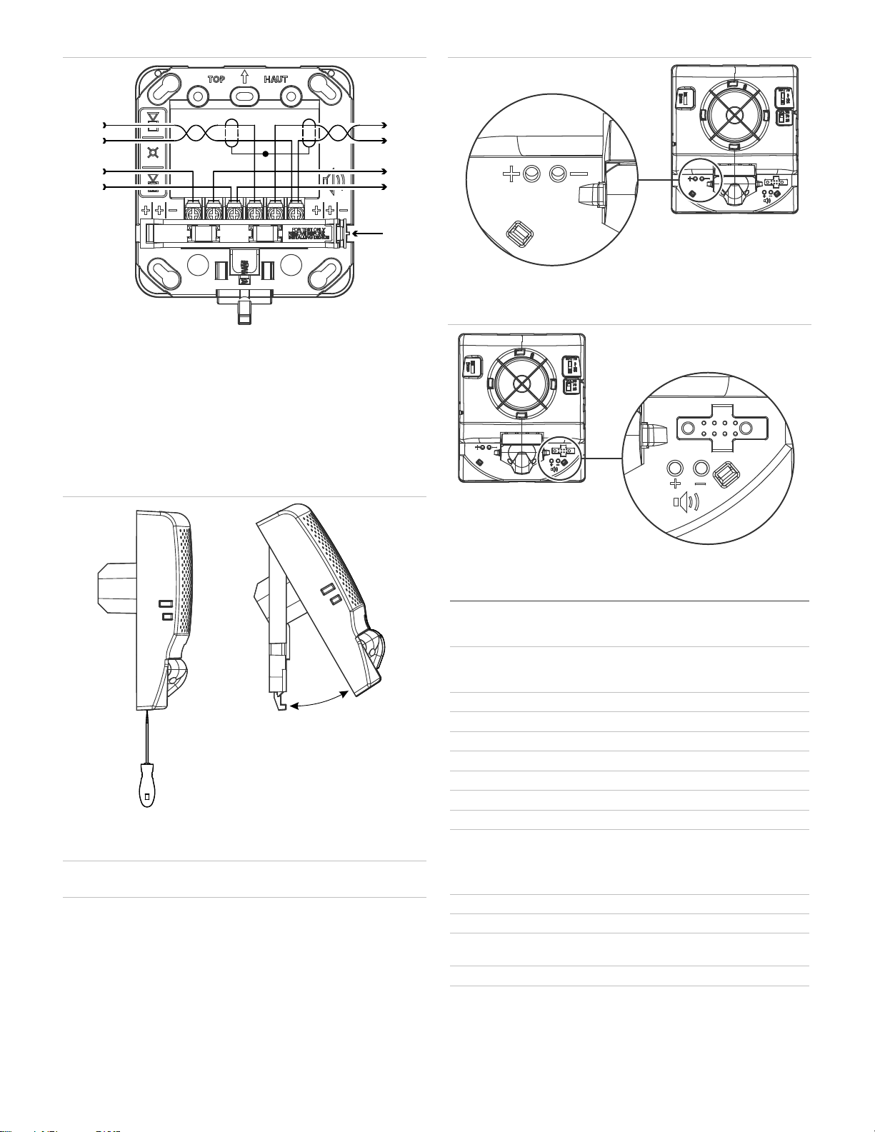
1. Remove the appliance cover. See Figure 1.
Insert a small, flat-bladed screwdriver into the slot at the bottom of
the appliance.
Gently pull up on the screwdriver to pry the bottom of the
appliance cover down and away from the appliance.
Lift the bottom of the cover out and over the top of the appliance.
2. On speakers and speaker-strobes, set the speaker wattage and
voltage switches for the required values. See Figure 2.
3. On speaker-strobes, set the strobe candela switch for the required
value. See Figure 3.
4. Replace the appliance cover.
Figure 1: Removing and replacing the cover
Figure 2: Speaker switch settings
firealarmresources.com
2 / 4 P/N 3102667-EN • REV 002 • ISS 31AUG20
Figure 3: Strobe switch settings
Installation
Install and wire this device in accordance with applicable national and
local codes, ordinances, and regulations.
Caution: Electrical supervision requires that you break the wire run at
each terminal. Do not loop the notification circuit field wires around the
terminals.
To install the appliance:
1. Using the screws supplied with the wiring plate, attach the wiring
plate and, if used, the trim plate to the electrical box. See Figure 4.
Do not overtighten the screws.
The trim plate is ordered separately.
2. Connect the field wiring. Observe signal polarity for the appliance
to operate properly. See Figure 5.
3. Remove the shorting clip (Figure 5, item 5). Retain for future use.
4. Plug the appliance into the wiring plate by setting the appliance on
the top of the wiring plate, and then snapping the bottom into
place. See Figure 6.
To unplug the appliance, press the spring clip on the bottom, and
then lift the appliance away from the mounting plate.
5. Test the unit for proper operation.
Figure 4: Typical electrical box mounting
(1) Electrical box
(2) Trim plate (optional)
(3) Wiring plate (required)
(4) Machine screw (2X, supplied with wiring plate)
(5) Notification appliance
(6) Shorting clip
Figure 5: Typical surface box mounting
(1) Surface box
(2) Wiring plate (required)
(3) Machine screw (2X, supplied with wiring plate)
(4) Notification appliance
(5) Shorting clip
110
15
30
75
(3)
(4)
(2)
(1)
(5)
(6)
(1)
(2)
(3)
(5)
(4)
firealarmresources.com
P/N 3102667-EN • REV 002 • ISS 31AUG20 3 / 4
Figure 6: Wiring
(1) Speaker circuit in (shields, if used, must be continuous and free
from earth ground except at the signal source)
(2) Strobe circuit in (signal polarity shown in the active condition)
(3) Speaker circuit out
(4) Strobe circuit out
(5) Shorting clip
Note: To maintain circuit continuity, do not remove the shorting clip
(Figure 6, item 5) until you are ready to install the notification
appliance.
Figure 7: Removing and replacing the appliance
Maintenance and testing
Caution: Equipment damage hazard. To maintain the required agency
listings, do not change factory-applied finishes.
This unit is not serviceable or repairable. If the unit fails to operate,
contact the supplier for a replacement.
Perform a visual and operational inspection in accordance with
applicable codes and standards or as directed by the local authority
having jurisdiction.
Input wiring test points are available on the front of the appliance when
the cover is removed. The test points let you easily spot check the field
circuit wiring without the need to remove the appliance from the wall.
See Figure 8 and Figure 9.
Figure 8: Strobe circuit test points
Note: Marking indicates signal polarity when the circuit is active.
Figure 9: Speaker circuit test points
Specifications
Operating voltage
Strobe
Speaker
16 to 33 VDC, 16 to 33 VFWR
25 VRMS, 70 VRMS (field selectable)
Operating current
16 to 33 VDC
16 to 33 VFWR
28 mA
36 mA
Supervisory voltage
30 V max.
Sound output
See Table 3 and Table 4
Speaker response
400 to 4,000 Hz
Resonant frequency
520 Hz
Strobe flash rate
1 fps (flash per second) approx.
Light output
15, 30, 75, or 110 cd
Light distribution
See Figure 10.
Synchronization
20 Ω max. between any two devices.
To determine allowed wire resistance, refer
to these specifications, and the specifications
for the synchronized signal source.
Dimension
s See Figure 11
Center
offset −1.70 in (−4.32 cm)
Compatible electrical
boxes
[1]
2-gang, 4-inch square, G4RSB, G4WSB
Wire size
12 to 18 AWG (0.75 to 2.50 mm²)
Screw torque
Mounting screws
Terminal screws
10 lbf-in (1.2 N-m) max.
12 lbf-in (1.4 N-m) max.
(2) –
+(4)
(5)
–
+
(1) –
+(3)
–
+
firealarmresources.com
4 / 4 P/N 3102667-EN • REV 002 • ISS 31AUG20
Trim plates
EG4TR, EG4TW
Replacement covers
See Table 5 and Table 6
Operating environment
Temperature
Relative humidity
32 to 122°F (0 to 50°C)
0 to 93% noncondensing
Storage temperature
-40 to 158°F (-40 to 70°C)
[1] Minimum box depth: 1.5 in. (3.81 cm)
Table 3: Sound level (dBA) at 3.05 m (10 ft.)
Voltage
setting
Wattage
setting
Reverberant
(UL 1480)
Anechoic
(CAN/ULC-S541)
25V / 70V
1/4W 78 78
1/2W 81 81
1W 84 84
2W 87 87
Table 4: Sound pattern (ULC)
Axis
Angle
Change in output
Horizontal
117° and 61° −3 dBA
134° and 49° −6 dBA
Vertical
128° and 68° −3 dBA
138° and 52° −6 dBA
Table 5: EG4S speaker replacement covers
Catalog
number Description
EG4SRF-CVR
Cover, wall speaker, red, FIRE
E
G4SRN-CVR Cover, wall speaker, red, no marking
E
G4SWA-CVR Cover, wall speaker, white, ALERT
EG4SWF
-CVR Cover, wall speaker, white, FIRE
E
G4SWN-CVR Cover, wall speaker, white, no marking
Table 6: EG4SV speaker-strobe replacement covers
Catalog number
Description
E
G4SVRF-CVR Cover, wall speaker-strobe, red, FIRE
E
G4SVRN-CVR Cover, wall speaker-strobe, red, no marking
EG4SVWA
-CVR Cover, wall speaker-strobe, white, ALERT
EG4SVWF
-CVR Cover, wall speaker-strobe, white, FIRE
EG4SVWN
-CVR Cover, wall speaker-
strobe, white, no marking
Contact information
For contact information, see www.kidde-esfire.com.
Figure 10: 110 cd light distribution
(1) Horizontal left
(
2) Horizontal right
(3) Vertical bottom
──────── Measured
─
────UL minimum
Figure 11: Dimensions
(1) 1.13 in. (2.87 cm)
(2) 1.62 in. (4.11 cm)
(3) 4.95 in. (12.57 cm)
(4) 5.78 in. (14.68 cm)
Regulatory information
UL rating
Regulated 24 DC and 24 FWR
FCC compliance
This device complies with part 15 of the FCC
Rules. Operation is subject to the following two
conditions: (1) This device may not cause harmful
interference, and (2) this device must accept any
interference received, including interference that
may cause undesired operation.
Industry Canada
compliance
This Class A digital apparatus complies with
Canadian ICES-003.
Environmental
class
Indoor, dry
(1) (2)
(3)
(4)
(2) (3)(1)
firealarmresources.com

Other Kidde Speakers manuals

Kidde RemoteLync User manual

Kidde

Kidde RemoteLync User manual

Kidde RemoteLync User manual

Kidde

Kidde RemoteLync User manual

Popular Speakers manuals by other brands

Vivitar SS27-PBS-TA user manual

Vivitar

Vivitar SS27-PBS-TA user manual

thomann The Box Pro Achat 215 user manual

thomann

thomann The Box Pro Achat 215 user manual

Sharkk Boombox manual

Sharkk

Sharkk Boombox manual

Code 3 C3100 Installation and operation instructions

Code 3

Code 3 C3100 Installation and operation instructions

DAPAudio X-15A quick start guide

DAPAudio

DAPAudio X-15A quick start guide

TP Radio TP Tube user guide

TP Radio

TP Radio TP Tube user guide

TREBLAB FX100 user manual

TREBLAB

TREBLAB FX100 user manual

Paradigm OM-140 owner's manual

Paradigm

Paradigm OM-140 owner's manual

pTron Musicbot CUBE user manual

pTron

pTron Musicbot CUBE user manual

Polk Audio 65-LS manual

Polk Audio

Polk Audio 65-LS manual

Denver BTL-31 quick start guide

Denver

Denver BTL-31 quick start guide

Kitsound DANCEFLOOR user manual

Kitsound

Kitsound DANCEFLOOR user manual

Paradigm PW 300 owner's manual

Paradigm

Paradigm PW 300 owner's manual

Steg SG650C user guide

Steg

Steg SG650C user guide

PEAS GS-215 user manual

PEAS

PEAS GS-215 user manual

Thiel PowerPoint 1.2 quick start

Thiel

Thiel PowerPoint 1.2 quick start

Mackie Thump12A quick start guide

Mackie

Mackie Thump12A quick start guide

Next PFA15 user manual

Next

Next PFA15 user manual

manuals.online logo
manuals.online logoBrands
  • About & Mission
  • Contact us
  • Privacy Policy
  • Terms and Conditions

Copyright 2025 Manuals.Online. All Rights Reserved.