Kieback&Peter GmbH & Co. KG
Tempelhofer Weg 50, 12347 Berlin/Germany
Telefon: +49 30 60095-0, Telefax: +49 30 60095-164
Datasheet 2.50-40.151-11-EN
SBM51/11
Issue 2014-11-19
A
Änderungen vorbehalten - Contents subject to change - Sous réserve de modifications - Reservado el derecho a modificación - Wijzigingen
voorbehouden - Con riserva di modifiche - Innehåll som skall ändras - Zmeny vyhradené - Změny vyhrazeny - Zmiany zastrzeżone - Возможны
изменения - A változtatások jogát fenntartjuk - ֱ⬭㒣䗮ⶹ㗠ᬍࡼⱘᴗ
Product Description
SBM51/11 Switch cabinet bus module
for energy monitoring devices A210/A220 and
A230/A230s with communication module EMMOD
201 from the company Camille Bauer
Application
The switch cabinet bus module SBM51/11 is used to
integrate up to 8 energy monitoring devices into the
DDC3000 or DDC4000 system via Modbus RTU.
Content Page
Important Information Regarding Product Safety ..................................................................................................2
Item........................................................................................................................................................................3
Technical Data.....................................................................................................................................................3
Dimensions..........................................................................................................................................................3
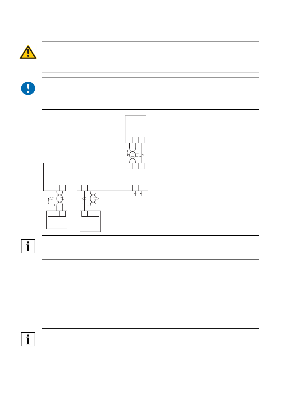
Connection...........................................................................................................................................................4
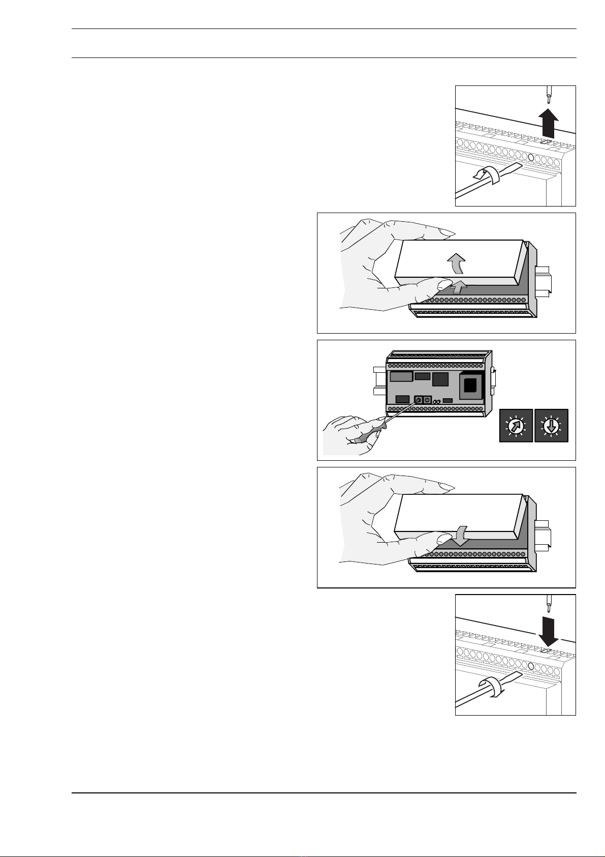
Mounting ................................................................................................................................................................5
Removal.................................................................................................................................................................5
Commissioning ......................................................................................................................................................6
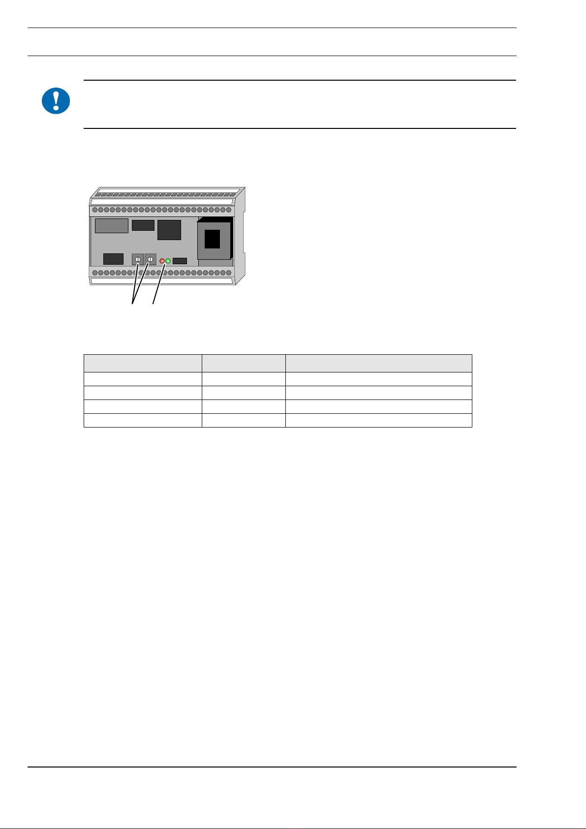
Indicators and Controls........................................................................................................................................6
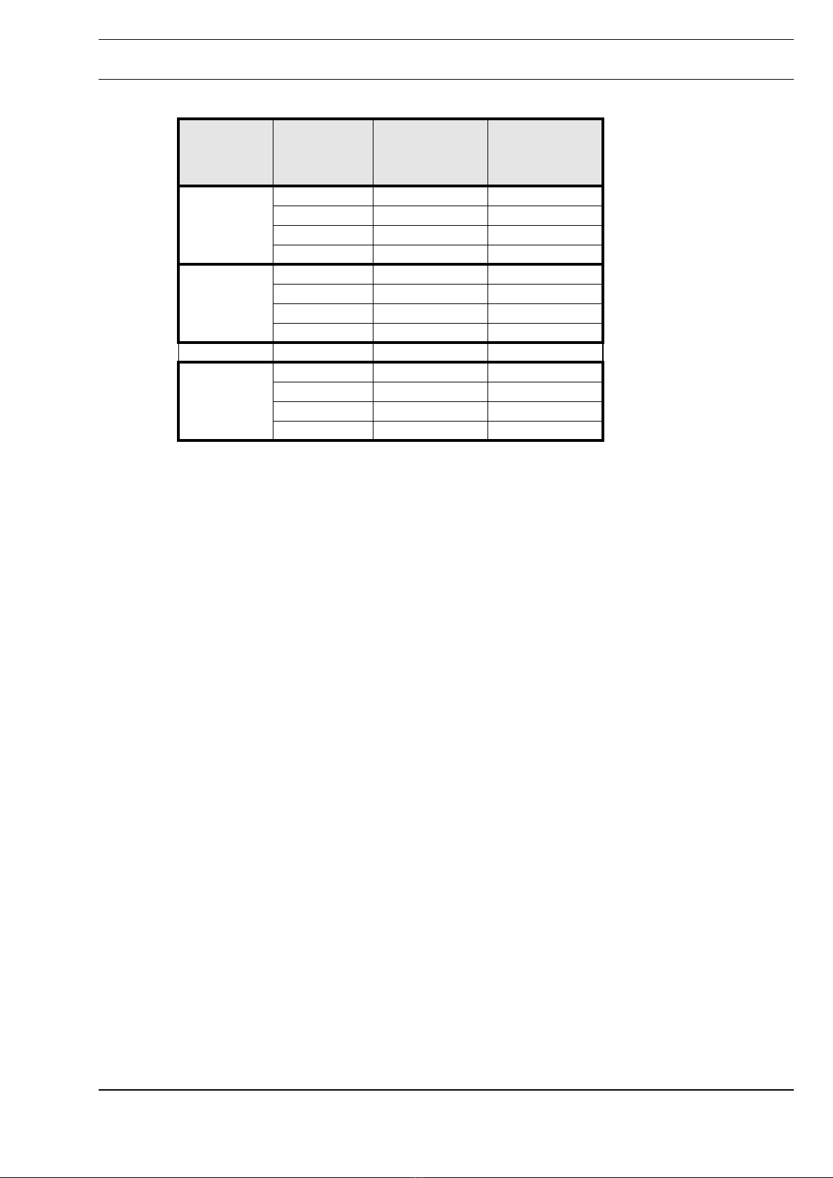
Setting the switch cabinet bus address ...............................................................................................................7
Description of Parameters .....................................................................................................................................8
Parameter List in the DDC3000 System..............................................................................................................8
Parameter List in the DDC4000 System..............................................................................................................8
Assignment of Software Menus / System Objects to the Energy Monitoring Devices.........................................9
Parameter Settings for the Energy Monitoring Devices.......................................................................................9
Points Lists ........................................................................................................................................................11
Reference Lists for Parameters according to Connection Type ........................................................................15