Kikusui PLZ2004WB User manual

PLZ2004WB/PLZ2004WHB 1
The PLZ2004WB/PLZ2004WHB Load Booster is used to increase the
input current to the PLZ1004W/PLZ1004WH Electronic Load. One
PLZ1004W/PLZ1004WH is made the master unit, and load boosters
connected in parallel operate as slave units.
Number of load
boosters
Maximum current/ Maximum power
PLZ2004WB PLZ2004WHB
1 600 A / 3 000 W 150 A / 3 000 W
2 1
000 A / 5 000 W 250 A / 5 000 W
3 1
400 A / 7 000 W 350 A / 7 000 W
4 1
800 A / 9 000 W 450 A / 9 000 W
About the Operation Manual
This manual contains an overview of the PLZ2004WB/PLZ2004WHB
electronic load booster and information about connecting,
maintenance, and using it. For information on how to perform parallel
operation, see the PLZ-4W/PLZ-4WH Series Electronic Load User's
Manual.
These operation manuals are intended for users of electronic loads
and their instructors. Explanations are given under the presumption
that the reader has knowledge about Power Supply.
Every effort has been made to ensure the accuracy of this manual.
However, if you have any questions or find any errors or omissions,
please contact your Kikusui agent or distributor.
If you find any misplaced or missing pages in the manuals, they will
be replaced. If the manual gets lost or soiled, a new copy can be
provided for a fee. In either case, please contact your Kikusui agent
or distributor, and provide the "Kikusui Part No." given on the cover.
After you have finished reading this manual, store it so that you can
use it for reference at any time.。
Features
• Up to four load boosters can be connected in parallel.
• The combination of PLZ2004WBs and a PLZ1004W master unit
can create an electronic load of up to 9 kW and 1 800 A.
The combination of PLZ2004WHBs and a PLZ1004WH master unit
can create an electronic load of up to 9 kW and 450 A.
The master unit displays the total current and total wattage. The
units connected in parallel can be used as a single electronic load.
• The connection of the control cables is easy. The control cable
used to connect between the master unit and the load booster and
between each load booster is one flat cable each.
• There is no power switch. The AC input power is turned ON/OFF
by the master unit.
Checking the Package Contents
When you receive the product, check that all accessories are
included and that the product and accessories have not been
damaged during transportation. If any of the accessories are
damaged or missing, contact Kikusui distributor/agent.
Accessories (PLZ2004WB)
Operation manual
(1 copy)
Load input terminal cover (2 pcs.)
[with auxiliary band]
Set of screws for the load
input terminal (2 sets)
[M1-100-027]
[M5-101-009]
[M4-100-009]
[Q1-500-096]
[Q1-900-020]
Power cord (1 pc.)
Heavy object warning label (1 pc.)
If necessary, attach to the product.
Plug: NEMA5-15
Rating: 125 Vac/10 A
[85-AA-0003]
Plug: CEE7/7
Rating: 250 Vac/10 A
[85-AA-0005]
Plug: GB1002
Rating: 250 Vac/10 A
[85-10-0790]
oror
The power cord that is provided varies depending on the
destination for the product at the factory-shipment.
Accessories (PLZ2004WHB)
Load input terminal cover (1 pc.)
Lock plate (2 pcs.)
Set of screws for the load
input terminal (2 sets)
[M1-100-012]
[M5-101-007]
[M4-100-007]
[Q1-500-085]
[P2-000-228]
Power cord (1 pc.)
Plug: NEMA5-15
Rating: 125 Vac/10 A
[85-AA-0004]
Plug: CEE7/7
Rating: 250 Vac/10 A
[85-AA-0005]
Plug: GB1002
Rating: 250 Vac/10 A
[85-10-0790]
oror
The power cord that is provided varies depending on the
destination for the product at the factory-shipment.
Operation manual
(1 copy)
Heavy object warning label (1 pc.)
If necessary, attach to the product.
The newest version of the operation manual can be downloaded from
Download service of Kikusui website.
Website http://www.kikusui.co.jp/en
KIKUSUI ELECTRONICS CORP.
1-1-3, Higashiyamata, Tsuzuki-ku, Yokohama,
224-0023, Japan
TEL: +81-45-593-0200 Fax: +81-45-593-7571
PA RT NO. Z1-005-160, IB022735
Oct. 2015
PLZ2004WB
PLZ2004WHB
Operation Manual
Electronic Load Booster

2 PLZ2004WB/PLZ2004WHB
Safety Symbols
For the safe use and safe maintenance of this product, the following
symbols are used throughout this manual and on the product.
Note the meaning of each of the symbols to ensure safe use of the
product. (Not all symbols may be used.)
or Indicates that a high voltage (over 1000 V) is used
here.
Touching the part causes a possibly fatal electric
shock. If physical contact is required by your work,
start work only after you make sure that no voltage
is output here.
DANGER Indicates an imminently hazardous situation which,
if ignored, will result in death or serious injury.
WARNING
Indicates a potentially hazardous situation which, if
ignored, could result in death or serious injury.
CAUTION
Indicates a potentially hazardous situation which, if
ignored, may result in damage to the product and
other property.
Shows that the act indicated is prohibited.
Indicates a general danger, warning, or caution.
When this symbol is marked on the product, see the
relevant sections in this manual.
Protective conductor terminal.
Chassis (frame) terminal.
On (supply)
Off (supply)
In position of a bi-stable push control
Out position of a bi-stable push control
Safety Precautions
The following safety precautions must be observed to avoid fire
hazards, electric shock, accidents, and other failures. Keep them in
mind and make sure to observe them.
Using the product in a manner that is not specified in this manual
may impair the protection functions provided by the product.
Users
Operation
Manual
• This product must be used only by qualified personnel
who understand the contents of this operation manual.
• If unqualified personnel is to use the product, be sure
the product is handled under the supervision of qualified
personnel (those who have electrical knowledge). This
is to prevent the possibility of personal injury.
Purpose • Never use the product for purposes other than the
productʼs intended use.
• This product is not designed or manufactured for
general home or consumer use.
Input power
Line
Voltage
• Use the product within the rated input power voltage
range.
• For applying power, use the power cord provided.
(see page 7 ).
• This product is designed as an equipment of
IEC Overvoltage Category II (energy-consuming
equipment supplied from the fixed installation).
Cover • Some parts inside the product may cause physical
hazards. Do not remove the external cover.
Grounding
GNL
• This product is IEC Safety Class I equipment
(equipment with a protective conductor terminal).
To prevent electric shock, be sure to connect the
protective conductor terminal of the product to
electrical ground (safety ground).
Operation
Check?
• If a malfunction or abnormality is detected on the
product, stop using it immediately, and remove
the power plug from the outlet or turn off the circuit
breaker of switchboard. Make sure the product is not
used until it is completely repaired.
• Do not disassemble or modify the product. If you need to
modify the product, contact your Kikusui distributor/agent.
Maintenance
and
Inspection
• To prevent the possibility of electric shock, remove
the power plug from the outlet or turn off the
circuit breaker of switchboard before carrying out
maintenance or inspection.
• Check periodically that there are no tears or breaks
in the power cord.
• If the panel needs cleaning, gently wipe it using a
soft cloth with water-diluted neutral detergent. Do not
use volatile chemicals such as benzene or thinner.
• To maintain the performance and safe operation of the
product, it is recommended that periodic maintenance,
inspection, cleaning, and calibration be performed.
Adjustments
and Repairs
• Kikusui service engineers will perform internal service
on the product. If the product needs adjustment or
repairs, contact your Kikusui distributor/agent.

PLZ2004WB/PLZ2004WHB 3
Precautions Concerning
Installation Location
Be sure to observe the following precautions when
installing the product.
• Do not use the product in a flammable atmosphere.
To prevent the possibility of explosion or fire, do not use the
product near alcohol, thinner, or other combustible materials, or in
an atmosphere containing such vapors.
• Avoid locations where the product is exposed to high
temperature or direct sunlight.
Do not install the product near a heater or in areas subject to
drastic temperature changes. For this product's operating and
storage temperatures, see this specifications.
• Avoid high humidity.
Do not install the product in high-humidity locations--near a boiler,
humidifier, or water supply. For this product's operating and
storage humidity, see this specifications. Condensation may occur
even within the operating humidity range. In such cases, do not
use the product until the condensation dries up completely.
• Be sure to use it indoors.
This product is designed for safe indoor use.
• Do not install the product in a corrosive atmosphere.
Do not install the product in a corrosive atmosphere or in
environments containing sulfuric acid mist, etc. This may cause
corrosion of various conductors and bad contacts of terminals
inside the power supply leading to malfunction and failure, or in the
worst case, a fire.
• Do not install the product in a dusty location.
Accumulation of dust can lead to electric shock or fire.
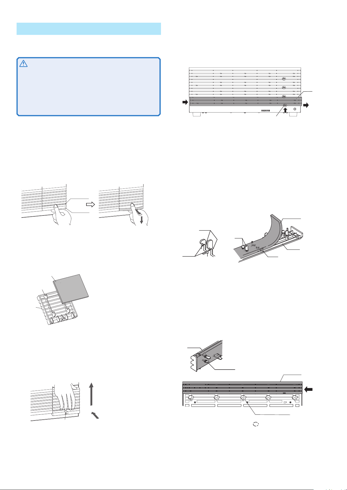
• Do not use the product where ventilation is poor.
Secure adequate space around the product so that air can
circulate around it. Allow at least 20 cm of space between the inlet
and vent holes and any walls or obstructions.
• Do not place objects on the product.
Placing objects on top of the product can cause failures (especially
heavy objects).
• Do not install the product on an inclined surface or location
subject to vibrations.
The product may fall and break or cause personal injury.
• Do not use the product in a location where strong magnetic
or electric fields are nearby or a location where large amount
of distortion and noise is present on the input power supply
waveform.
The product may malfunction.
• Do not stack more than two units on top of each other.
The units (load booster and master unit) can be stacked, but
do not stack more than two units on top of each other for safety
reasons. If you are using multiple load boosters, it is recommended
that they be mounted on a rack.
POWER
ELECTRONIC LOAD
PLZ2004WHB
POWER
ELECTRONIC LOAD
PLZ2004WHB POWER
ELECTRONIC LOAD
PLZ2004WHB
I MONOUTOUTTRIG
I MONOUTOUTTRIG
REMOTE
POWER
Do not stack more than two units.
Precautions to Be Taken When
Moving the Product
Note the following points when moving or transporting
the product to the installation location.
• Turn off the power switch.
Moving the product while the power is turned on can cause
electric shock or damage to it.
• Have two or more people move the unit.
The unit weighs over 20 kg. Have two or more people move the
unit. Use extra precaution at inclines and steps.
• Remove all wiring.
Moving the product with the wires connected can cause wires to
break or injuries due to the product falling over.
• When transporting the product, be sure to use the original
packing materials.
Otherwise, damage may result from vibrations or from the
product falling during transportation.
• Be sure to include this manual.
Notation Used in the Guide
• In this manual, the PLZ-4W Series Electronic Load is sometimes
referred to as the “PLZ-4W Series”or "booster." In this manual,
the PLZ-4WH Series Electronic Load is sometimes referred to as
the “PLZ-4WH Series”or "booster."
• In this manual, the PLZ2004W Electronic Load is sometimes
referred to as the “PLZ2004W.”In this manual, the PLZ2004WH
Electronic Load is sometimes referred to as the “PLZ2004WH.”
• The following markings are used in the explanations in the text.
WARNING
• Indicates a potentially hazardous situation which, if ignored,
could result in death or serious injury.
CAUTION
• Indicates a potentially hazardous situation which, if ignored,
may result in damage to the product and other property.
>Indicates menu settings that you select. The menu item to
the left of the > symbol is a higher level menu.

4 PLZ2004WB/PLZ2004WHB
Front Panel and Rear Panel
1. POWER lamp
Illuminates when the power switch of
the master unit is on when the load
booster is connected in parallel with
the master unit. It indicates that AC
input power is being supplied.
2. Air intake (louver)
Inlet port used to exhaust the internal
heat using a fan.
3. J1 and J2 connectors
(only on the PLZ2004WB)
Connectors used to connect the
optional flat cable to enable parallel
operation. The upper connector
is the J1 connector, and the lower
connector is the J2 connector.
4. PARALLEL connector
(only on the PLZ2004WHB)
Connectors used to connect the
optional flat cable to enable parallel
operation. The upper connector
is the IN connector, and the lower
connector is the OUT connector.
5. Remote sensing terminal
(only on the PLZ2004WHB)
The remote sensing terminal is not
used.
6. DC INPUT
(Load input terminal)
Input connector used to connect to
the equipment under test.
7. AC INPUT connector
AC power input connector.
8. Serial number
9. Air outlet
Air outlet used to exhaust the internal
heat using a fan.
POWER
ELECTRONIC LOAD 2000W
x
-
xxxV
0
-
xxxA
PLZ2004WB
DC INPUT
2000W
1. 5
-
150V
0
-
400A
AC INPUT
100
-
240V
47
-
63Hz
200VA MAX
J1
J2
PROTECTIVE GROUNDING CONDUCTOR MUST
BE CONNECTED TO GROUND.
DO NOT REMOVE COVERS, REFER
SERVICING TO QUALIFIED PERSONNEL.
TO AVOID ELECTRIC SHOCK, THE POWER CORD
WARNING
ᆬȾ٥ȪȹȧΈႊȢȳȨȗǿ
టᛏֿɁɵʚ˂ɂፏߦȾɝ۶ȪȹɂȗȤɑȮɦǿ
᩻ඨɁȲɔǾоӌໃɽ˂ʓɁÇÎÄ፷ɥ
ឬ֖
POWER
ELECTRONIC LOAD
PLZ2004WHB
2000W
5
-
650V
0
-
100A
IN
OUT
PARALLEL
100
-
240V
50
-
60Hz
200VA MAX
AC INPUT
DC INPUT 2000W 5
-
650V 0
-
100A
ᧄຠ䈱䉦䊋
䊷
䈲䇮⛘ኻ䈮ข䉍ᄖ䈚䈩䈲䈇䈔䉁䈞䉖䇯
ౝㇱ䈱ὐᬌ䈲ᒰ␠䈏䉄䈢䉰
䊷
䊎䉴䊙䊮䈮ᆔ⸤䈚䈩䈒䈣䈘䈇䇯
㔚Ḯ䉮
䊷
䊄䈶⽶⩄✢䈱ข䉍ᛒ䈇䈲䇮ᔅ䈝㔚Ḯ䊒䊤䉫䉕ᛮ䈇䈩䈎䉌ⴕ䈦䈩䈒䈣䈘䈇䇯
⼊๔
DO NOT REMOVE COVERS.
NO OPERATOR SERVICEABLE PA RTS INSIDE.REFER SERVICING
TO QUALIFIED SERVICE PERSONNEL.
UNPLUG THE MAINS SUPPLY CORD BEFORE
HANDLING THE CORD OR
LOAD WIRES.
WARNING
WEIGHT APPROX 24kg
Æòïîôðáîåì
ÐÌÚ²°°´×Â
ÐÌÚ²°°´×ÈÂ
Òåáòðáîåì
Æòïîôðáîåì
Òåáòðáîåì
²
±
·¹
¸
²
±
´
µ
·¹¸
¶³

PLZ2004WB/PLZ2004WHB 5
Use a signal wire to connect the load booster to the master unit. Use
a load wire to connect the load booster to the EUT.
You can connect up to four boosters.
Separate the load cable from the flat cable as much as possible to
prevent unstable operation.
DC INPUT
2000W
1.5
-
150V
0
-
400A
J1
J2
DC INPUT
2000W
1.5
-
150V
0
-
400A
J1
J2
J1
J2
DC INPUT
1000W
1.5
-
150V
0
-
200A
+
–
–+
–+
–+
Example:
Parallel connection of
two load boosters
Equipment
under test
Flat cable
PC02-PLZ-4W (Option)
Flat cable
PC01-PLZ-4W
(Option)
Master unit
Load booster 1
Load booster 2
Load wire
Connecting the Signal Cables
[84-49-0071]
A protective socket is attached to the J1 connector
(PLZ2004WB) or PARALLEL connector
(PLZ2004WHB) when the PLZ2004WB/PLZ2004WHB
is in the factory default state. Keep the protective
socket in a safe place so that you can attach it to the
connector when the connector is not in use. If the
protective socket is damaged or lost, contact your
Kikusui agent or distributor.
Use the optional flat cable for the signal
wire. It comes in two lengths.
Model Length Explanation
PC01-PLZ-4W 300 mm (11.81") For connecting boosters to each other
PC02-PLZ-4W 550 mm (21.65") For connecting the master unit to a booster
CAUTION
To avoid damaging the product, observe the following precautions.
• Do not connect the cables to the wrong connectors.
• Do not operate the PLZ-4W or PLZ4WH alone with the flat cable
connected.
• Do not mix the PLZ2004WB and PLZ2004WHB units together in
parallel operation.
1
Check that the master unit's POWER switch is turned
off ( ○).
2
Check that the booster power cords are not
connected.
3
If you are using PLZ2004WBs, connect the J2
connector of the master unit to the J1 connector of
the first booster.
If you are using PLZ2004WHBs, connect the
PARALLEL OUT connector of the master unit to the
PARALLEL IN connector of the first booster.
4
If you are using PLZ2004WBs, connect the J2
connector of the first booster to the J1 connector of
the second booster.
If you are using PLZ2004WHBs, connect the
PARALLEL OUT connector of the first booster to the
PARALLEL IN connector of the second booster.
Continue connecting all the remaining boosters in the
same manner.
This completes the procedure for connecting the signal wires.
Load wiring
The cautions and things that you need to consider when you are
wiring the loads are the same as when you are wiring the loads of
the PLZ1004W/PLZ1004WH. To ensure operational stability, see
"Methods for Ensuring Stable Operation" in chapter 1, "Installation
and Preparation" of the PLZ1004W/PLZ1004WH User's Manual.
WARNING
• Improper use of load wires may lead to fire. Use load wires whose
capacity is adequate for the PLZ-4W/PLZ-4WH's rated output current.
• Possible electric shock. Use load wires whose rated voltage meets
or exceeds the PLZ-4W/PLZ-4WH's isolation voltage. For details
of isolation voltage, see "General specifications" of this manual.
CAUTION
Use a load wire with sufficient diameter for the current as well as
non-flammable or flame-resistant cover.
If the wiring that you use for the load has a high resistance, the
voltage will drop significantly when current flows, and the voltage
at the load input terminals may fall below the minimum operating
voltage. Using the following table as a reference, select wiring whose
nominal cross-sectional area is as thick as possible.
A wire's temperature is determined by the resistive loss based on
the current, the ambient temperature, and the wire's external thermal
resistance. The following table shows the current capacity of heat-
resistant vinyl wires that have a maximum allowable temperature of 60
ºC when one of the wires is separated and stretched out horizontally in
air in an ambient temperature of 30 ºC. The current must be reduced
under certain conditions, such as when vinyl wires that have a low heat
resistance are used, when the ambient temperature is 30 ºC or greater,
or when wires are bundled together and little heat is radiated.
Nominal Cross-
Sectional Area
[mm2]
AWG (Reference Cross-
Sectional Area)
[mm2]
Allowable Current1
[A] (Ta = 30 ºC)
Kikusui-
Recommended
Current [A]
2 14 (2.08) 27 10
3.5 12 (3.31) 37 -
5.5 10 (5.26) 49 20
8 8 (8.37) 61 30
14 6 (13.3) 88 50
22 4 (21.15) 115 80
30 2 (33.62) 139 -
38 1 (42.41) 162 100
50 1/0 (53.49) 190 -
60 2/0 (67.43) 217 -
80 3/0 (85.01) 257 200
100 4/0 (107.2) 298 -
125 - - 344 -
150 - - 395 300
200 - - 469 -
250 - - 556 -
325 - - 650 -
1. Excerpts from Japanese laws related to electrical equipment.
Parallel Connection

6 PLZ2004WB/PLZ2004WHB
Connecting the Load Wires
Consider the current that you will be using, and use wires that are
thick as possible. Also, wire them as short as possible. Use load
wires that have the same length and cross-sectional area.
The load input terminal of the master unit (PLZ1004W/PLZ1004WH) is
not designed to handle as large a current as the load input terminal
of the booster. Separate the load wires that are connected to the EUT
into those that are connected to the master unit and those that are
connected to the boosters.
Master unit
Load input
terminals
Load input
terminals
Load input
terminals
Equipment under test
Use wires that are as thick as possible,
and wire them as short as possible.
Use load wires that have the same length
and cross-sectional area.
Booster 1
Booster 2
Example: Connection
of two boosters
WARNING
Possible electric shock.
• Do not touch the load input terminal while the power is on.
• Be sure to use the load input terminal cover.
CAUTION
• To avoid damaging the product, observe the following
precautions. Be sure to use the load input terminals on the rear
panel on the master unit. Do not connect other equipment to the
load input terminal on the front panel.
• There is a danger of overcharge. Attach crimping terminal to the
wire and use the set of screws that came with the package for
connection.
■Connecting load wires to the PLZ2004WB
1
Check that the POWER switch of master unit is off ( ).
2
Check that the booster power cords are not
connected.
3
Make sure that the output of the EUT is off.
4
Connect load wires to the load input terminal on the
master unit's rear panel as shown in the PLZ1004W
user's manual.
5
Connect the load wires to the load input terminals on
the booster using the included load input terminal
screw set.
Bolt (M12 × 25)
Spring washer (M12)
Nut (M12)
Crimping terminal
Be sure to use the
included screw set.
6
For each of the booster's load input terminals, wrap
the included auxiliary band around the space between
the rear panel and the bolt.
The auxiliary band prevents the load input terminal cover from
slipping. Wrap the belt tightly to fill in the space between the
panel and the bolt.
Wrap the auxiliary band around the space
between the rear panel and the bolt.
Wrap the belt tightly to fill in the space
between the panel and the bolt.
Auxiliary band
7
Wrap the load input terminal covers around the
booster's load input terminals.
Wrap the load input cover over
the auxiliary band and the load
input terminal.
Wrap the load input
terminal cover so that
there is as little space
here as possible.
Load input terminal
cover
8
Connect the load wires of the master unit and the
boosters to the EUT.
9
Check the polarity of the connections.
This completes the procedure for connecting the load wires.
■Connecting load wires to the PLZ2004WHB
The methods for connecting load wires to a booster's load input
terminal and for using the load input terminal covers and lock plates
are the same as the methods for the PLZ1004WH. For details, see the
PLZ1004WH user's manual.
1
Check that the POWER switch of master unit is off (
).
2
Check that the booster power cords are not
connected.
3
Make sure that the output of the EUT is off.
4
Connect load wires to the load input terminal on the
master unit's rear panel as shown in the PLZ1004WH
user's manual.
5
Connect load wires to the load input terminal on the
booster as shown in the PLZ1004WH user's manual.
6
Connect the load wires of the master unit and the
boosters to the EUT.
7
Check the polarity of the connections.
This completes the procedure for connecting the load wires.

PLZ2004WB/PLZ2004WHB 7
Connecting the Power Cord
This product falls under IEC Overvoltage Category II (energy-
consuming equipment supplied from the fixed installation).
WARNING
Possible electric shock.
• This product is IEC Safety Class I equipment (equipment with
a protective conductor terminal). Be sure to earth ground the
product to prevent electric shock.
• Connect the protective conductor terminal to earth ground.
Use the supplied power cord to connect to an AC power line.
If the supplied power cord cannot be used because the rated voltage
or the plug shape is incompatible, have a qualified engineer replace
it with an appropriate power cord that is 3 m or less in length. If
obtaining an appropriate power cord is difficult, consult your Kikusui
agent or distributor.
A power cord with a plug can be used to disconnect the product
from the AC line in an emergency. Connect the plug to an easily
accessible power outlet so that the plug can be removed from the
outlet at any time. Be sure to provide adequate clearance around the
power outlet.
Do not use the supplied power cord for other devices.
The load booster does not have a power switch. The AC input power
is turned on/off in sync with the master unit.
1
Check that the AC power supply is within the input
power supply range of the product.
The voltage that can be applied is any of the nominal power
supply voltages in the range of 100 Vac to 240 Vac. The
frequency is 50 Hz or 60 Hz.
2
Connect the power cord to the AC INPUT connector
on the rear panel.
3
Connect the power cord plug to an outlet with a
ground terminal.
Setting the Master Unit
After you finish making the connections, set the number of boosters
on the master unit.
If the master unit's response speed has been set to 1/1, its response
speed is changed to 1/2 to ensure operational stability. You can use
the menu settings to return the response speed to 1/1.
1
Turn on ( ) the power to the master unit.
On the master unit, from the menu, select "2. Configuration" >
"1.Master/Slave" > "Operation" > "MASTER."
2
Set "Booster" to the number of booster units that
have been connected.
3
Turn off ( ) the power to the master unit.
The menu settings are applied. This completes the settings that
are necessary to use boosters.
Performing Parallel Operation
After you finish configuring the settings on the master unit, you can
perform parallel operation. During parallel operation, the slew rate
and response speed settings on the master unit are used.
If large voltage drops occur because of increased wiring inductance
or if oscillations occur due to instability of the product caused by
current phase lag, reduce the response speed to ensure stable
operation.
Turning the Power On and Off
■Turning the power on
Turn the master unit's POWER switch on. This will also turn the
boosters on.
Set the operation mode and configure the settings on the master unit,
and turn the load on.
■Turning the power off
Turn the master unit's POWER switch off. This will also turn the
boosters off.
Ending Parallel Operation
To end parallel operation and return to independent operation, turn
the master unit off, and then remove the flat cables.
To return the master unit to independent operation, from the menu,
select "2. Configuration" > "1.Master/Slave" > "Booster" > "-," and then
restart the unit.
CAUTION
To avoid damaging the product, observe the following precautions.
Do not operate the PLZ-4W or PLZ-4WH alone with the flat cable
connected.

8 PLZ2004WB/PLZ2004WHB
Cleaning the Dust Filter
A dust filter is installed on the inside of the louver on the front panel.
Periodically clean the filter to prevent clogging.
CAUTION
• Clogged dust filters hinder the cooling of the inside of the
instrument and can cause a malfunction and shortening of the
service life.
• When the Booster is in operation, air is sucked through the dust
filter to cool the load booster. If moister is included in the dust
filter, the temperature or humidity inside the Booster increases
and may cause a malfunction.
■Cleaning the PLZ2004WB's dust filter
1
Remove the louver from the panel by placing a finger
on the 2nd level of the louver and pulling down the
1st level while pulling it toward you.
If the louver does not come off easily, pressing down the top
level of the louver will ease the work.
1st level
2nd level
2
Remove the dust filter from the inside of the louver
and clean it.
Remove the dust on the dust filter such as by using a vacuum
cleaner. If the filter is extremely dirty, clean it using a water-
diluted neutral detergent and dry it completely.
Dust filter
Louver
Tab
3
Attach the dust filter to the louver.
Firmly attach the dust filter so that the louver's tabs protrude out
of the top of the dust filter.
4
Attach the louver to the panel by pulling up on the
louver while holding the 2nd level of the louver with
your hand until the pin is fixed in place.
Pin
■Cleaning the PLZ2004WHB's dust filter
1
Remove the lower louver from the panel.
While lifting the bottom of the removal mark with your finger tips,
slide the entire louver to the right. Then, pull it toward you.
POWER
ELECTRONIC LOAD
PLZ2004WHB
2000W
5
-
650V
0
-
100A
①
②
②
While lifting the bottom of the removal mark with your finger tips (①),
slide the entire louver to the right (②).
Removal mark
Louver
2
Remove all the remaining louvers in the same manner
as was shown in step 1.
3
Remove the dust filter from the inside of the louver
and clean it.
There is a hook on the louver tab. Be sure not to get the dust
filter caught in the hook when removing the dust filter from the
louver.
Remove the dust on the dust filter such as by using a vacuum
cleaner. If the filter is extremely dirty, clean it using a water-
diluted neutral detergent and dry it completely.
Hook
Hook
Louver
Dust filter
Tab
Guide
4
Align the dust filter along the guide and attach it to
the louver.
Be sure to attach it firmly until the tab hooks of the louver
completely passes through the dust filter.
5
Attach the upper louver first.
Align the tab on the inner side of the louver to the panel groove
and slide the louver to the left to attach it. You can easily attach
the louver by aligning the long tabs (five locations) with the
grooves.
Tab (long)
Tab (short)
Upper louver
Groove for attaching the louver
Pass the long tabs on the back side of the louver through
the grooves on the panel indicated by circles.
Slide the louver to the left to lock the louver in place.
6
Attach all the remaining louvers in the same manner
as was shown in step 5.

PLZ2004WB/PLZ2004WHB 9
Calibration
The booster is shipped from the factory after carrying out a strict
calibration. However, to maintain the performance, periodic
calibration is recommended.
Calibrate the master unit and the boosters as a single electronic load
in the same manner as when you calibrate the master unit alone.
For details, see "Calibration" in the PLZ1004W/PLZ1004WH User's
Manual.
For calibration, use shunt resistors and a regulated DC power supply
that match the product's current capacity.
Rack mount bracket
The following brackets are available as options.
Inch-rack EIA standard Milli rack JIS standard
PLZ2004WB KRB3-TOS KRB150-TOS
PLZ2004WHB KRB4 KRB200
For details, contact Kikusui distributor/agent.
465 (18.31)
479 (18.86)
57
(2.24)
132 (5.20)
37.5
(1.48)
KRB3-TOS
460 (18.11)
479 (18.86)
100
(3.94)
149 (5.87)
24.5
(0.965)
KRB150-TOS
KRB4
457.5 (18.01)
102
(4.02)
177 (6.97)
37.5
(1.475)
478.9 (18.85)
KRB200
457.5 (18.01)
478.9 (18.85)
199 (7.83)
50
(1.97)
50
(1.97)
50
(1.97)
24.5
(0.96)
Unit: mm (inch)
PLZ2004WB
PLZ2004WB
PLZ2004WHB
PLZ2004WHB
Specifications
Electrical Specifications
Unless specified otherwise, the specifications are for the following
settings and conditions.
• Warm-up period: 30 minutes (with current flowing)
• Ambient temperature: 23 ºC5 ºC
• TYP: These are typical values that are representative of situations
where the PLZ2004WB/PLZ2004WHB operates in an environment
with an ambient temperature of 23 ºC. These values do not
guarantee the performance of the PLZ2004WB/PLZ2004WHB.
• % of set denotes % of the input voltage or input current setting.
• % of f.s denotes % of the rated input voltage, rated input current or
rated input power.
• % of reading denotes % of the input voltage or input current reading.
■Rating (PLZ2004WB)
PLZ2004WB
Operating voltage 1.5 Vdc to 150 Vdc1
Current 400 A
Power 2 000 W
Current setting accuracy2(1.2 % of set + 1.1 % of f.s)3
1. Minimum voltage at which the current starts flowing to the PLZ2004WB is approx.
0.3 V. The PLZ2004WB detects no signal at an input voltage less than or equal to
approx. 0.3 V and an input current less than or equal to approx. 1 % of the range
rating. If the input voltage is gradually increased from 0 V, no current will flow until
0.3 V is exceeded. Once a current greater than or equal to 1 % of the range rating
starts flowing, the current can flow at voltages less than equal to 0.3 V.
2. Condition in which the booster is connected to the master unit.
3. M range applies to the full scale of H range.
■Rating (PLZ2004WHB)
PLZ2004WHB
Operating voltage 5 Vdc to 650 Vdc1
Current 100 A
Power 2 000 W
Input resistance when the load is off 2.21 MΩ2
1. Minimum voltage at which the current starts flowing to the PLZ2004WHB is approx.
0.5 V. The PLZ2004WHB detects no signal at an input voltage less than or equal to
approx. 0.5 V and an input current less than or equal to approx. 1 % of the range
rating. If the input voltage is gradually increased from 0 V, no current will flow until
0.5 V is exceeded. Once a current greater than or equal to 1 % of the range rating
starts flowing, the current can flow at voltages less than equal to 0.5 V.
2. Condition in which the booster is connected to the master unit.
• Constant current (CC) mode
PLZ2004WHB H range M range L range
Operating range 0 A to 100 A 0 A to 10 A 0 A to 1 A
Setting range 0 A to 105 A 0 A to 10.5 A 0 A to 1.05 A
Resolution110 mA 1 mA 0.1 mA
Ripple1PLZ1004WH specification x (total power capacity/1 kW) (TYP)
1. When one PLZ2004WHB is connected.
2. Condition in which the booster is connected to the master unit.
• Accuracy of setting
PLZ2004WHB
CC mode1(1.2 % of set + 1.1 % of f.s2)
CR mode (1.2 % of set + 1.1 % of f.s2)(TYP)
CV mode (0.2 % of set + 0.2 % of f.s)(TYP)
CP mode (5 % of f.s2)(TYP), at 23℃5℃
1. Condition in which the booster is connected to the master unit.
2. The full scale of the range. However, for the M range, it is the full scale of the H range.
• Measurements
PLZ2004WHB
Accuracy of voltmeter (0.1 % of reading + 0.1 % of f.s)(TYP)
Accuracy of ammeter (1.2 % of reading + 1.1 % of f.s1)(TYP)
Wattmeter Displays the product of the voltmeter reading and
ammeter reading.
1. The full scale of the range. However, for the M range, it is the full scale of the H range.
■Protection function
Protection functions other than those listed below operate on the PLZ1004W/
PLZ1004WH. For details, see the PLZ-4W/PLZ-4WH user's manual.
PLZ2004WB/PLZ2004WHB
Overheat protection (OHP) Turns off the load when the heat sink
temperature reaches 95 ºC
Reverse connection protection (REV) Protection by fuse

10 PLZ2004WB/PLZ2004WHB
■General Specifications
PLZ2004WB PLZ2004WHB
Environment Operating
temperature range
0 ºC to 40 ºC (32 ºF to 104 ºF)
Operating humidity
range
20 %rh to 85 %rh (no condensation)
Storage
temperature range
-25 ºC to 70 ºC (-13 ºF to 158 ºF)
Storage humidity
range
Less than or equal to 90 %rh (no
condensation)
Input line voltage range 100 Vac to 240 Vac
(90 Vac to 250 Vac) single phase, continuous
Input frequency range 47 Hz to 63 Hz
Power consumption 200 VAmax
Inrush current 35 A 120 A1
Protective conductor current --- 600 µA (100 Vac at
50 Hz; TYP)
Insulation
resistance
Primary - input
connector,
Primary - chassis,
Input connector -
chassis
500 Vdc,
30 MΩor more
(ambient humidity of
70 %rh or less)
1 000 Vdc,
30 MΩor more
(ambient humidity of
70 %rh or less)
Withstand
voltage
Primary - input
connector,
Primary - chassis,
No abnormalities at 1 500 Vac for 1 minute
Dimensions See outline drawing.
Weight Approx. 24 kg (52.91 lb)
Accessories Power cord 1 pc. (Cable length of 2.4 m)
Load input terminal
cover
2 sets (cover and
auxiliary band)
1 pc. (cover and two
lock plates)
Screw set for th
load input
2 sets (bolts, nuts, and spring washers)
Heavy object
warning label
1 pc.
Operation manual 1 pc.
Electromagnetic compatibility
(EMC)3 4
Conforms to the requirements of the
following directive and standard.
EMC Directive 2014/30/EU
EN 61326-1
EN 61000-3-2
EN 61000-3-3
Safety 3 Conforms to the requirements of the
following directive and standard.
Low Voltage Directive 2014/35/EU4
EN 61010-1 (Class I
5
, Pollution degree 2
6
)
1. Approximately 70 A when 100 Vac is applied
2. If the input voltage or input frequency is different, the following equation can be
used to calculate the value.
Input voltage [V] Input frequency [Hz]
Protective conductor current =
×
× 600 [µA]
100 [V] 50 [Hz]
3. Not applicable to custom order models.
4. Only on models that have CE marking on the panel.
5. This instrument is a Class I equipment. Be sure to ground the protective conductor
terminal of the instrument. The safety of the instrument is not guaranteed unless
the instrument is grounded properly
6. Pollution is addition of foreign matter (solid, liquid or gaseous) that may produce a
reduction of dielectric strength or surface resistivity. Pollution Degree 2 assumes
that only non-conductive pollution will occur except for an occasional temporary
conductivity caused by condensation.
Dimensions
PLZ2004WB Unit: mm (inch)
MAX150
(5.91)
128 (5.04)
429.5 (16.91)
MAX440 (17.32)
550 (21.65)
MAX600 (23.62)
430 (16.93)
173 (6.81)
MAX190 (7.48)
550 (21.65)
MAX590 (23.23)
PLZ2004WHB Unit: mm (inch)
Trademarks
Microsoft and Windows are either registered trademarks or
trademarks of Microsoft Corporation in the United States and/or other
countries.
Other company names and product names used in this manual are
generally trademarks or registered trademarks of the respective
companies.
Inquiry about Product
When making an inquiry about the product, please provide us with
the following information.
Model (indicated at the top section on the front panel)
Serial number (indicated at the bottom section on the rear panel)
Copyrights
Reproducing or reprinting this operation manual or any part of it
without the permission of the copyright holder is strictly prohibited.
Product specifications and manual contents are subject to change
without notice.
© 2010 Kikusui Electronics Corp.
10
环境保护使用期限
Environment-friendly Use Period
该标记为适用于在中华人民共和国销售的电子信息产品的环境保
护使用期限。
只要遵守有关该产品的安全及使用注意事项,从制造年月起计算,
在该年度内,就不会对环境污染、人身、财产产生重大的影响。
产品的废弃请遵守有关规定。
产品的制造年月可以在以下网址中确认。
http://www.kikusui.co.jp/pi/
有毒有害物质或元素名称及含有標示
Name of hazardous materials and symbol of element in the
equipment and quantity
部件名称
有毒有害物质或元素
铅
Pb
汞
Hg
镉
Cd
六价铬
Cr(VI)
多溴联
苯
PBB
多溴二
苯醚
PBDE
印刷电路板组装品 × ○ × ○ ○ ○
内部接线 × ○ ○ ○ ○ ○
外壳 × ○ ○ ○ ○ ○
底盘组装品 × ○ × ○ ○ ○
辅助设备 × ○ ○ ○ ○ ○
本表格依据 SJ/T 11364 的规定编制。
○: 该部件所有均质材料的有毒有害物质的含量不超过 GB/T 26572 标
准所规定的极限值要求。
×: 该部件至少有一种均质材料的有毒有害物质的含量超过 GB/T 26572
标准所规定的极限值要求。
This manual suits for next models
1
Table of contents
Other Kikusui Extender manuals