Tupavco TEX-200 User manual

VDSL2 Ethernet Extender
User Manual
Tupavco TEX-200
Version 1.1
Issued 12/30/2019

TUPAVCO TEX-200 VDSL2 ETHERNET EXTENDER –UM V1.1
I
Table of Contents
Introduction.....................................................................................................................1
1.1 Features ...................................................................................................................1
1.2 Specifications............................................................................................................2
1.3 Applications ..............................................................................................................3
1.4 Reference Performance Data....................................................................................3
2Hardware Description .....................................................................................................4
Mechanical Dimensions............................................................................................4
Connector Architecture .............................................................................................5
3LED Definition .................................................................................................................6
LED Indicators ..........................................................................................................6
4Power Connection...........................................................................................................6
54-Position DIP Switch......................................................................................................7
6Description of Setting.....................................................................................................8

TUPAVCO TEX-200 VDSL2 ETHERNET EXTENDER –UM V1.1
1
Introduction
TUPAVCO TEX-200 is an Ultra-Speed Gigabit Ethernet Copper Extender that supports a
remarkable aggregated bandwidth up to 300Mbps (Downstream: 150 Mbps/Upstream: 150
Mbps). It delivers fiber-optic like speeds on existing copper infrastructure, enabling a good
alternative in place where fiber is not economical to deploy. The TEX-200 is equipped with a
Gigabit Ethernet Port (RJ-45 connector) and one VDSL2 port (RJ-45 connector). 8 different
profile settings can be flexibly selected via dip switches to suit various applications and
environments. Symmetric profile can be applied as a standard Ethernet connection while
Asymmetric profile can be used for other services like Video streaming or IP surveillance
services which require high traffic flow in an uni-direction configuration. The TEX-200 supports
transparent LAN bridging to extend Ethernet service over UTP, Cat 5+ or Coaxial cables. With
TUPAVCO TEX-200’s superior performance in its category, it is the best high throughput Long
Reach Ethernet Extenders for service providers to deploy their IP-based networking services to
meet various application scenarios.
1.1 Features
High speed Ethernet extension over UTP, CAT 5e/6/7 or Coaxial cables.
Support ITU-T G.993.5 G.vectoring and G.INP
Selectable 8 different profile settings via Dip Switch (G.INP/Interleaved, Target SNR
6/8/12/24 dB, Symmetric/Asymmetric Modes)
Configurable SNR profile for noisy environment
Cost effective bridge function to connect two Ethernet LAN
IEEE 802.1Q VLAN tag transparent
Easy installation via simple plug-and-play

TUPAVCO TEX-200 VDSL2 ETHERNET EXTENDER –UM V1.1
2
Specifications
VDSL2 Interface
RJ-45 connector
DMT Encoding
Complying with ITU-T
G993.1/G993.2/G993.5/G.997.1/G.998
G.INP
On-board surge protection
LAN Interface
1 x RJ-45 connector
10/100/1000 Base-T; Auto-Negotiation, Auto-
MDI/MDI-X.
Complying with IEEE 802.3/802.3u/802.3z
4-position DIP Switch
Selectable Master(OT) or Remote(RT) mode
Selectable 8 different profile settings via Dip
Switch (G.INP/Interleaved, Target SNR
6/8/12/24 dB, Symmetric/Asymmetric Modes)
LED
Power: On/Off
LAN: Fast Ethernet/Gigabit Ethernet
VDSL2: Mode - CO (OT) / CPE (RT)
Sync - Idle / Training / Link
Power Supply
12-24 Vdc over 2.1mm DC Jack (Commercial
Grade External Power Adaptor included)
Power Consumption: 4.5 Watts (Max)
Physical Characteristics
Dimension (W x H x D): 96.2 x 22.8 x 73.4 mm
Installation(Optional): Wall Mounting or Media
Converter Chassis
Environment
Operating Temperature: 0°C ~45°C
Humidity: 0%~95%RH (non-condensing)
Regulatory Compliance
CE Class A
FCC Part 15B Class A
EN60950
Front Panel
Performance
UTP, 26AWG
Profile Setting 1: Symmetric, SNR 8dB, G.INP
Distance
(Feet)
Upstream Line Rate
(Mbps)
Downstream Line Rate
(Mbps)
500
155
158
1,000
122
126
1,500
75
80
2,000
48
56
2,500
28
38
3,000
23
28
UTP, 26AWG
Profile Setting 1: Asymmetric, SNR 8dB, G.INP
Distance
(Feet)
Upstream Line Rate
(Mbps)
Downstream Line Rate
(Mbps)
500
100
200
1,000
77
170
1,500
38
105
2,000
22
64
2,500
10
43
3,000
9
42
4,000
6
34
**The above performance data is for reference only, the
actual data rate may vary depending on the quality of the
coaxial cable and environmental factors.

TUPAVCO TEX-200 VDSL2 ETHERNET EXTENDER –UM V1.1
3
1.2 Applications
The solution works in pairs for point to point connectivity. One unit must be configured as Master
(OT) while the other unit must be configured as Remote (RT) by using Dip Switch.
1.3 Reference Performance Data
26AWG Copper Wire
UTP, 26AWG
Profile Setting 1: Symmetric, SNR 8dB, G.INP
Distance (Feet)
Upstream Line Rate (Mbps)
Downstream Line Rate (Mbps)
500
155
158
1,000
122
126
1,500
75
80
2,000
48
56
2,500
28
38
3,000
23
28
UTP, 26AWG
Profile Setting 1: Asymmetric, SNR 8dB, G.INP
Distance (Feet)
Upstream Line Rate (Mbps)
Downstream Line Rate (Mbps)
500
100
200
1,000
77
170
1,500
38
105
2,000
22
64
2,500
10
43
3,000
9
42
4,000
6
34
* The above performance data is for reference only, the actual data rate may vary
depending on the quality of the copper wire and environmental factors.

TUPAVCO TEX-200 VDSL2 ETHERNET EXTENDER –UM V1.1
4
2Hardware Description
Tupavco TEX-200 is a Long Reach Ethernet Extender. This chapter shows the product outlook
and hardware interfaces.
Mechanical Dimensions
Front Panel

TUPAVCO TEX-200 VDSL2 ETHERNET EXTENDER –UM V1.1
5
Connector Architecture
Ethernet Port Connector
(RJ-45)
The Ethernet Port interface is an 8-position Modular Jack. The table below displays the pin out
assignments.
Pin Number
Name
Description
1
BI_DA+
Bi-directional pair A +
2
BI_DA-
Bi-directional pair A -
3
BI_DB+
Bi-directional pair B +
4
BI_DC+
Bi-directional pair C +
5
BI_DC-
Bi-directional pair C -
6
BI_DB-
Bi-directional pair B -
7
BI_DD+
Bi-directional pair D +
8
BI_DD-
Bi-directional pair D -
VDSL2 Interface Pin Assignments (RJ-45)
The VDSL2 interface is standard eight-pin modular jack. The table below displays the pin out
assignments.
Pin Number
Description
Figure
1
Not used
18
Top View
18
Front View
2
Not used
3
Not used
4
ANALOG Input / Output
5
ANALOG Input / Output
6
Not used
7
Not used
8
Not used

TUPAVCO TEX-200 VDSL2 ETHERNET EXTENDER –UM V1.1
6
3LED Definition
LED Indicators
The LED indicators could provide instant feedback to users; the behaviors of the LED are given
in below table.
(1) LEDs for VDSL2
LED
Blinking
On
Off
PWR
Device Power On
Device Power Off
RT
CPE (Remote)
CO (Master)
LNK
Slow: Idle
Fast: Training /
Data Transmitting
Link UP
Link Down
(2) LEDs for Ethernet Port
LED
Blinking
On
Off
10
Data Transmitting
Reception of data
occurring at speed of
10Mbps
Link Down
100
Data Transmitting
Reception of data
occurring at speed of
100Mbps
Link Down
1000
Data Transmitting
Reception of data
occurring at speed of
1,000Mbps
Link Down
4Power Connection
1. 12-24 Vdc over 2.1mm DC Jack (Commercial Grade External Power Adaptor included)
2. Power Consumption: 4.5 Watts maximum

TUPAVCO TEX-200 VDSL2 ETHERNET EXTENDER –UM V1.1
7
54-Position DIP Switch
The device is equipped with DIP Switch selection which allows users to select the parameters
in order to meet the needs of different applications. Dip Switch 1 allows you to configure the unit
as Master (OT) or Remote (RT). Usually, the Master unit is located at the central office site of
Service Providers or Headquarter of Enterprise while the Remote unit is located at home, remote
sites or branch offices. Please note the Remote Unit (RT) will always follow the setting of
Master Unit (OT). When the unit operates in RT (CPE) Mode, Dip Switches 2,3,4 have no
functions.When the unit operates in OT(Master) Mode, Dip Switches supports 8 different profile
settings for different applications and environments.
Note:
There are four white buttons for DIP Switch. Moving the white button up position, its function is
“Off”. Moving the white button down position, its function is “On”.
Role
DIP Switch
Symmetrical/
Asymmetrical
G.INP/
Interleaved
Mode
Target SNR
Margin (dB)
Max Data Rate
DS/US (Mbps)
1
2
3
4
Master
(OT)
Symmetrical
G.INP
8
160/160
Asymmetrical
G.INP
8
220/110
Symmetrical
Interleaved
6
160/160
Asymmetrical
Interleaved
6
220/110
Symmetrical
G.INP
12
150/150
Asymmetrical
G.INP
12
220/100
*Special Profile
Setting for poor
environment
Symmetrical
(Forcing 30a profile
to link, and disable
band 0 to 2.2MHz)
G.INP
24
20/20
Asymmetrical
(Standard profile
Annex A 17a-eu32)
Interleaved
6
150/50
Remote
(RT)
Remote Unit (RT) will always follow the setting of Master Unit (OT). When the unit
operates in RT (CPE) Mode, DIP Switches 2,3,4 have no functions.

TUPAVCO TEX-200 VDSL2 ETHERNET EXTENDER –UM V1.1
8
6Description of Setting
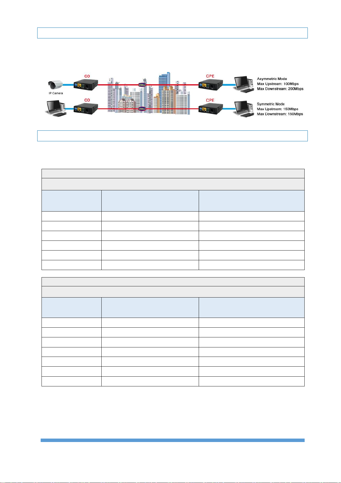
1. Symmetrical profile - Downstream and upstream rate are symmetrical.
2. Asymmetrical profile - Downstream and upstream rate are asymmetrical. Asymmetric
profile can beused for services like Video streaming or IPsurveillance services which require
high traffic flow in an uni-direction configuration.
3. GINP - Retransmission mode that provides enhanced protection against impulse noise or to
increase the efficiency of providing impulse noise protection (INP).
4. Interleaved - Interleaved mode has a slower transfer rate and increase latency in exchange
for error correction. A general line setting mode that provides common impulse noise
protection.
5. Max Data Rate Downstream/ Upstream -This parameter specifies the maximum net data
rate for the bearer channel as desired by the operator of the system. The data rate is coded
in steps of 1000 bit/s (G.997.1).
6. Target SNR Margin Downstream/ Upstream setting -This is the Noise Margin the xTU-
R/C receiver shall achieve, relative to the BER requirement for each of the downstream
bearer channels, or better, to successfully complete initialization. (G.997.1)
7. Special Profile Setting (Dip2: Off, Dip3: On, Dip4: On) is for application of near end
distance or poor environment, Target SNR Margin is set to high value of 24dB and rate limit
at 20Mbps to ensure channel stability. In addition, band 0 to 2.2MHz is disable to avoid
possible effects by low frequency. Because this item is set to 30a profile, so its train up time
is about 15sec to 20sec.
8. Profile Setting (Dip2: On, Dip3: On, Dip4: On) is standard profile Annex A 17a-eu32.

TUPAVCO TEX-200 VDSL2 ETHERNET EXTENDER –UM V1.1
9
Precautions and Safety Warnings
●Disconnect all power from devices before attempting installation.
●This device is intended for installation only in restricted access locations as
defined where both these conditions apply:
▪Access is through the use of a lock or tool and key, or other means of security, and is
controlled by the authority responsible for the location.
▪Access can only be gained by service persons or by users who have been instructed
about the reasons for the restrictions applied to the location and about any precautions
that shall be taken.
●All electric installations must be carried out in accordance with local and national
regulations.
●Do not work on the system, connect or disconnect cables during periods of lightning
activity.
Note:
●To reduce potential safety issues, only the AC Adapter provided with the product, a
replacement AC Adapter provided by agency, or an AC adapter purchased as an
accessory from agency should be used with the product.
Table of contents
Popular Extender manuals by other brands

Key Digital
Key Digital KD-EX18G operating instructions

Ihse
Ihse 474 Series user manual

NTI
NTI XTENDEX Series Installation and operation manual

Patton electronics
Patton electronics COPPERLINK 2151 user manual

Wilson Electronics
Wilson Electronics Mobile 4G 460021 user manual

AV Access
AV Access 4KIP100-KVM user manual