Page 1
IMPORTANT!
The satellite TV market is expanding and changing. The information in this manual was accurate at the
time of printing. If your Sea-King does not operate as outlined in this manual please call King Controls at
(800) 982-9920 or visit our website at www.kingcontrols.com.
Please read this entire manual before beginning the installation.
DISH NETWORK - EXPRESSVU: If you plan to use the Sea-King with multiple satellite programming and
would like to use the auto-switching feature, your receiver must be configured.
To configure the DISH receiver for automatic satellite switching, the antenna must be on the ground, dock
or motionless platform with no movement (see pages 24-27).
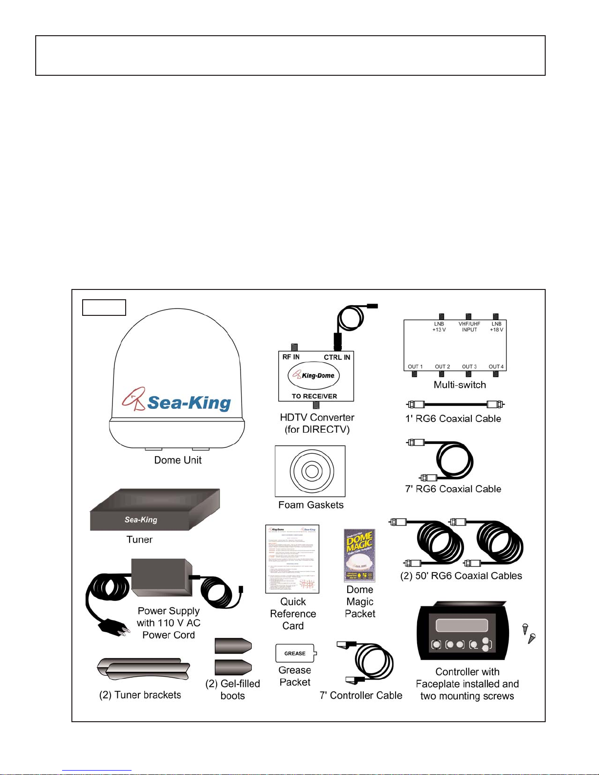
DIRECTV: This antenna will receive available HDTV programming from DIRECTV Ku band satellites at
101°, 110° and 119° with a properly installed HD converter accessory #9747 (included). It will not receive
channels broadcast from DIRECTV’s Ka band satellites at 99° and 103°.
TABLE OF CONTENTS
Section Contents Page
1. INTRODUCTION............................................................................................................2
2. DEFINITION OF TERMS...............................................................................................3
3. INSTALLATION.........................................................................................................4-17
4. OPERATION...........................................................................................................18-21
5. AUTOMATIC SATELLITE SWITCHING: DIRECTV®..............................................22-23
6. AUTOMATIC SATELLITE SWITCHING: DISH NETWORKTM - EXPRESSVU.........24-27
7. TROUBLESHOOTING............................................................................................28-31
8. MAINTENANCE...........................................................................................................32
9. LIMITED WARRANTY .................................................................................................33
DIRECTV®is a registered trademark of DIRECTV, Inc.
Dish NetworkTM is an official trademark of Echostar Communications Corporation.
Bell ExpressVu is an official trademark of Bell Canada.
DVB is a trademark of the DVB Digital Video Broadcast Project (1991-1996)
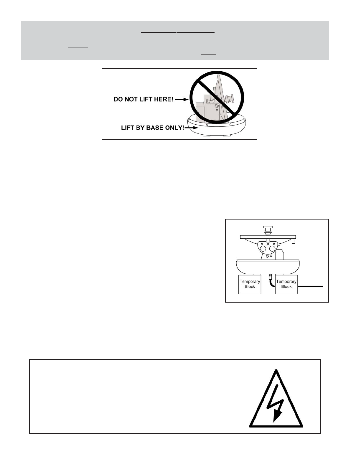
ELECTRICAL HAZARD WARNING!
The coaxial cable that connects the dome unit to the tuner carries a
24 volt electrical current. Exercise extreme caution when handling
this cable. Do not cut, break, or splice this line. Do not insert or
connect any devices such as splitters or any other device for any
reason. This line is not compatible with any other equipment.
Damage will occur to any device other than the dome unit if
connected to the antenna port on the tuner.