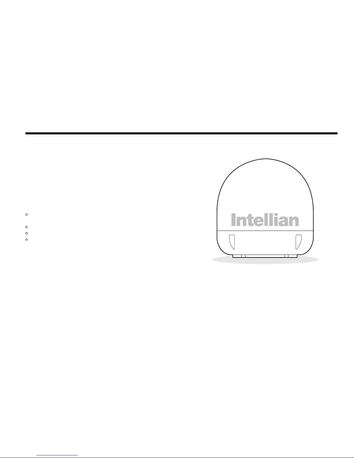
Intellian i6W User manual

i6W
Installation and Operation
User Guide
Document Number: 2012G3-UM1004-V1_0

2
Intellian Satellite TV Antenna Systems
Intellian i6W Serial Number
This serial number will be requested for all troubleshooting or service Inquiries.
Notice
All Right Reserved
Intellian i6W®and Intellian®are the registered trademarks of Intellian Technologies, Inc., and should not be appropriated without permission by Intellian
Technologies, Inc., and the information contained in this manual is the property of Intellian Technologies, Inc. Any and all parts of this manual shall not be
reproduced and distributed in any form without prior written consent by Intellian Technologies, Inc. The information contained in this manual shall be subject to
change at any time without notice due to the functional upgrades of the product.

3
INTRODUCTION
INTRODUCTION TO INTELLIAN i6W
FEATURES OF INTELLIAN i6W
BASIC SYSTEM CONFIGURATION OF INTELLIAN i6W
INSTALLATION THE ANTENNA
SYSTEM COMPONENTS
TOOLS REQUIRED FOR INSTALLATION
PLANNING THE INSTALLATION
INSTALLING THE ACU
ACU DIMENSIONS
CONNECTING THE SYSTEM TO A GPS
AUTO LNB SKEW ANGLE ADJUSTMENT
OPERATION INSTRUCTION
INTRODUCTION
OPERATING THE ACU
ACU SOFT KEYS
NORMAL MODE
SETUP MODE
OPERATION USING PC CONTROLLER PROGRAM
INTRODUCTION
PROGRAM INITIALING AND SERIAL PORT SETUP
MAIN MENU
CONTROLLER MENUS
PREPARATION FOR TRANSPORTATION
WARRANTY
APPENDIX : TECHNICAL SPECIFICATION
4
4
5
6
7
7
10
11
18
18
20
21
22
22
22
22
23
26
46
46
47
48
50
59
60
61
Table of Contents

4
Intellian Satellite TV Antenna Systems
Introduction to Intellian i6W
With its 60cm dish and 2-axis stabilized platform, the Intellian i6W is
the world’s rst global satellite TV antenna that receives multi-band
and multi- polarized satellite TV services as well as the latest advanced
DVB-S2 programming without any antenna hardware changes each
time the vessel crosses into a different satellite service region.
Integrated with the second generation WorldViewTM LNB module, the i6W
offers a rock-solid and the highest stability of ±25kHz for TV reception.
The Intellian WorldViewTM LNB module is designed and manufactured by
Intellian’s in-house engineering professionals, which allows boaters to
tune in any channel on any satellite and automatically switch between
circular polarized programming in North, Central and South America, and
linear polarized programming in Europe, Middle East,
and the Asia Pacic regions.
The i6W is able to withstand severe shock and vibration generated by
the marine environment. With a simplied yet sophisticated mechanical
design and excellent satellite tracking capability, the i6W is recognized
as the real denition for satellite TV system at sea.
Introduction

5
Features of Intellian i6W
Global Satellite Services Compatibility
Intellian i6W provides the ultimate convenience to connect you to
thousands of free TV, pay TV, Standard Denition, and High Denition
programming all over the world. It uses one LNB module which
incorporates multi (8) LO frequencies and multi-polarizations.
WorldviewTM LNB Module
The Intellian WorldviewTM LNB module is built with the highest
stability of ±25KHz that is required. It is used on the most of marine
communication systems today to guarantee the most reliable TV
receptions. In addition, this LNB module receives multi-band and multi-
polarization satellite TV services around the globe. Boaters don’t need
to manually change LNB inside the antenna dome each time the vessel
crosses into a different satellite service region.
DVB-S2 Digital TV Receptions
Some of the HDTV services have moved onto DVB-S2 and will be more
in the future. Thanks to Intellian’s groundbreaking DVB-S2 digital TV
technology, now you can enjoy your favorite DTH entertainment at sea,
just like home.
Global Satellite Library
The i6W includes the pre-programmed global satellite library which
allows you to select the desired satellite while travelling from region to
region. Once the satellite is selected, the WorldViewTM LNB module will
automatically switch to the corresponding local frequency and receive
the signal.
Easy Installation and Outstanding Reliability
Intellian i6W adopts a single-cable connection design from the antenna
to the antenna control unit. It provides a highly reliable system through
the implementation of a modularized design and the usage of strictly
proven components.

6
Intellian Satellite TV Antenna Systems
Figure 01: Basic System Conguration
Basic System Congurations
For your satellite TV system to work properly, the system will have to be
connected with all of the provided components properly, as shown in
the gure below (see the “Installation” section of this manual). Separate
purchase of a satellite receiver and a TV is required.
Note: Dish Network and Bell TV users please refer to the Intellian Dish
Network MIM Installation and User Manuals.
ACU
RF 1 RF 2
9-30V DC Power NMEA GPS PC Cable
Satellite Receiver (IRD)
NMEA
ANT RF1 RECEIVER
FUSEDC 9 - 30 V PC INTERFACE
FG - +
+ -
Satellite Receiver (IRD)
TV
7
Figure 02: Antenna Unit
System Components
The Intellian i6W consists of two major units, antenna assembly unit and
antenna control unit.
Antenna Unit
The antenna of Intellian i6W is manufactured with the following components
for the optimum search and reception of the satellite signal.
• Mechanical Unit – manipulates the antenna to receive the optimal
satellite signal regardless of the movement of the vessel.
• Control Unit – controls mechanical operation of the antenna.
• RF Unit – transmits the optimum satellite signal to the receiver.
• Radome – protects the antenna from the severe marine environment.
Installation
8
Intellian Satellite TV Antenna Systems
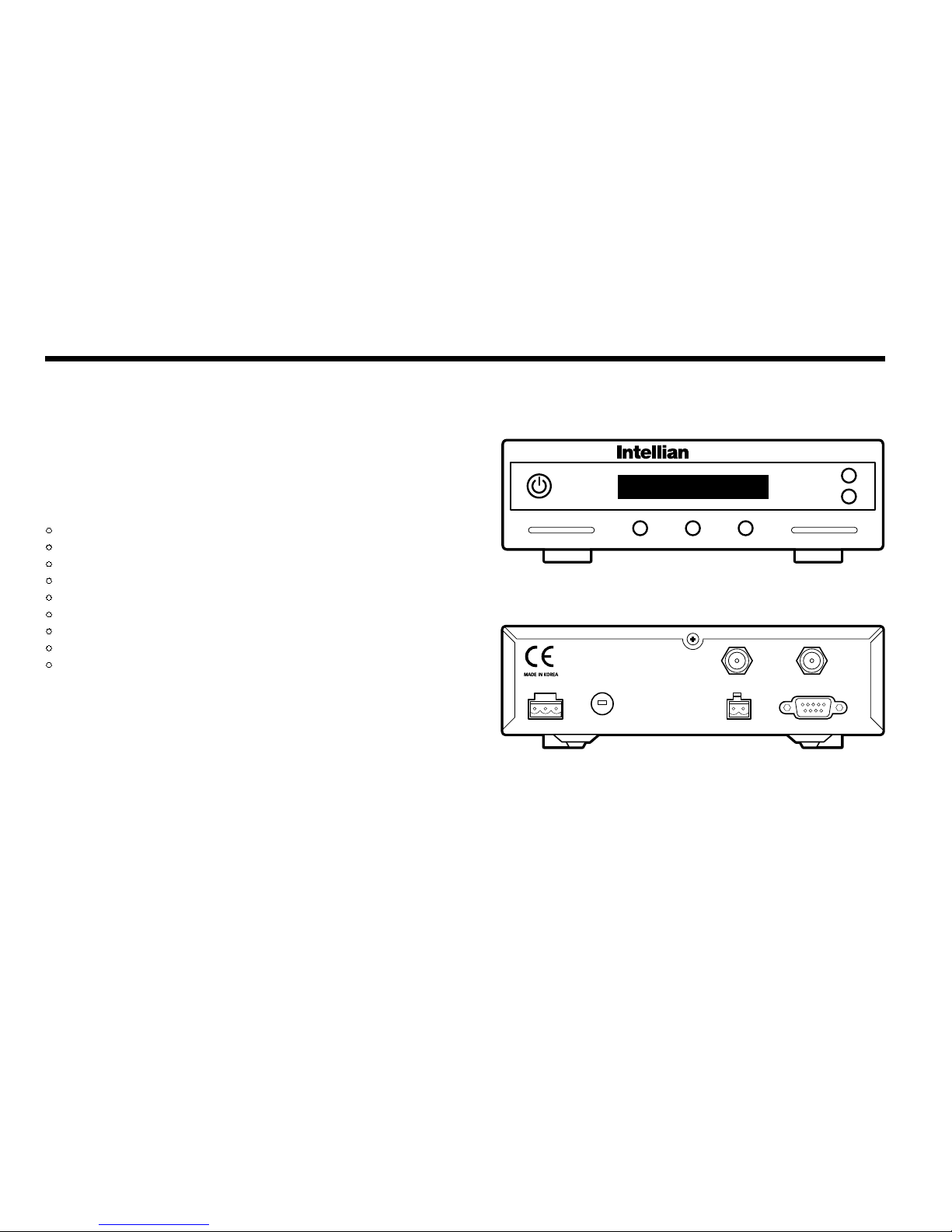
Figure 03 : Antenna Control Unit (ACU)
Antenna Control Unit (ACU)
Antenna Control Unit (ACU) provides the power to the antenna and
controls the various settings of the antenna. Additionally, Vacuum
Fluorescent Display (VFD) allows for you to operate the ACU in the dark.
The functions of ACU are as follows:
• Provide power for the antenna unit
• Monitor the antenna status
• Change the target satellite
• Set up the user environment
• Set the current GPS information
• Set satellite information
• Move antenna manually
• Perform self-diagnosis of the antenna
• Set up the interface with a PC
NMEA
ANT RF1 RECEIVER
FUSEDC 9~30V PC INTERFACE
FG - +
+ -
Front
Rear
Antenna Control Unit

9
Installation Kit
Contains the items required for securing the antenna unit and ACU to the vessel.
Other Components
Figure 05 : List of the Supplied Parts
Figure 04 : Installation Bolt Kit
4 Power Cable 10m 1
5 PC Serial Cable 1.8m 1
6 NMEA Connector AK950-2 1
7 Power Connector AK950-3 1
8
Hex Bolt M8x50L 5
Self-Tapping Screw ø4x16L 5
ø3x8L 5
Flat Washer M8 5
Spring Washer M8 5
Nut M8 5
9 Install CD - 1
10 Manual - 1
11 Mounting Template - 1
12 Quick Installation Guide - 1
No Components Size Qty
1 ACU Bracket - 2
2 RG6
(Antenna - ACU RF Cable) 15m 1
3 RG6 (ACU - IRD Cable) 3m 1
Hex.Bolt
5
Hex.Head
Wrench Bolt
5
-
Flat Washer
5
Hex. Nut
5
Spring Washer
5
Antenna
Item
Qty
Item
Qty
Size
Self-Tapping Screw
5
(M4 X 16L)
Machine Screw
5
(M3 X 8L)
ACU

10
Intellian Satellite TV Antenna Systems
Tools Required for Installation
Figure 06 : Required Tools for Installation
Power Drill 11 mm Spanner
Cross-Head
Screwdriver 13 mm Spanner
10 mm Drill Bit
Ø80 mm
Hole Saw
Pencil
5 mm
Allen/Hex key

11
Planning the Installation
Selection of Antenna Installation Site
Install the antenna in accordance with the following procedures to
insure maximum performance.
The antenna should be installed in a place where there is all round clear
view of the horizon. Please be sure there are no obstacles within 15°
above the antenna. Any obstacles can prevent the antenna from tracking
the satellite signal (Refer to the drawing on the right).
Do not install the antenna near the radar especially on the same plane.
Its energy levels may overload the antenna front-end circuits. It is
recommended to position the antenna at least 4 feet (1.2m) above or
below the level of the radar and minimum of 15 feet (4.6m) away from
the high power short wave radars.
The mounting platform should be rigid and not subjected to excessive
vibration. The movement of the antenna can be minimized by installing
at the center of the vessel. For optimal performance of the antenna, it
is not recommended to install at any corner of the vessel, where the
movement of the vessel is the greatest. Install the bottom of the antenna
parallel to the surface of the sea and x tightly to the structure of the
vessel.
Figure 07 : Elevation Limit of Obstacles
15°
Antenna Unit Obstacle

12
Intellian Satellite TV Antenna Systems
Extending the Cables
The cables that have been supplied with your Intellian system should be
of adequate length to complete the installation on most boats.
Power Cable
This cable supplied at a length of 10m.
Note: Exceeding the indicated cable lengths will result in reduced
performance of your system.
Cables
Before installing the system cables, consider the following points.
• All cables need to be well clamped and protected from physical
damage and exposure to heat and humidity.
• Cables with severe bends are not allowed.
• Where a cable passes through an exposed bulkhead or deckhead,
a watertight grommet or swan neck tube should be used.
Power Requirements
You need to follow the power requirements to avoid damage the system.
Intellian i6W has been designed to work on a boat’s power supply rated
at 12V / 24 V DC (acceptable range: 9~30 V DC).
If your IRD(s) and television(s) require a 110V/240V AC power supply,
you will need to install a suitable DC to AC converter to operate the
unit(s) from your boat’s DC power supply.
RF Cable
This cable supplied at a length of 15m. If a longer length is required you should
replace this cabel with an extended RF cable.

13
Installation and Mounting of Antenna
The method of installation and mounting of the antenna may vary due
to vessel design but the following procedures are applicable in most
situations, and will result in a secure and effective installation.
Conrmation of Size Prior to Installation
• Conrm the height and diameter of the bottom surface of
the antenna before installing.
• The space must be sufcient for installing the antenna unit
considering the height and diameter of the antenna.
• The height and the diameter of the bottom surface of the antenna are
as shown in the following drawing. If possible, install the antenna
using a power tower.
Note: Before installing the antenna open the radome and remove the
shipping constraints from the antenna interior. Reinstall the radome
before operating the system. The system will not perform properly if the
radome is open.
Figure 08 : Radome Dimension of i6W
Ø70 cm (27.5”)
72 cm (28.3”)
14
Intellian Satellite TV Antenna Systems
Mark of the Antenna Mounting Position
Referring to the mounting template, mark where antenna will be
mounted onboard (it must be a at surface) or on a separate power
tower.
Note: If a power tower is not suitable to mount the antenna, separate
cable shock and waterproong measures must be taken to protect the
RF connector from being exposed to the sea water and external shocks.
An exposed cable may cause electric shock and cause serious damage
to the equipment.
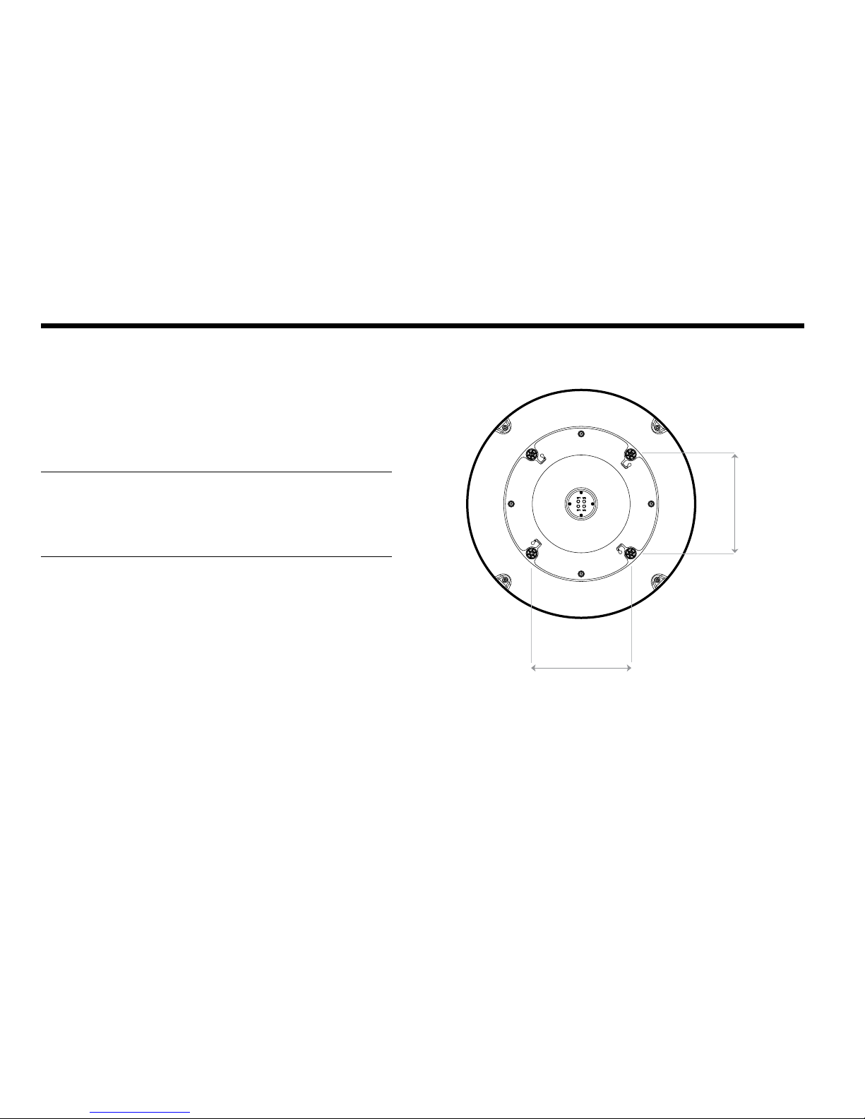
Figure 09 : Mounting Hole Position of i6W
30.4cm (12”)
30.4 cm (12”)

15
Connection of the Cable
Remove the rubber cap from RF connector. Connect the RF cable to the
RF connector under the base plate through the access hole using an
11mm spanner. Be careful not to over tighten, as you may damage the
connector.
Note: Do not use excessive force when using the spanner, this will
damage the threads. Be careful that the connectors do not contact the
mounting surface of the antenna, this may cause a critical malfunction
and serious damage to the equipment.
Securing Holes for Bolts and Cable Ways
Make 4 bolt holes of 10mm diameter, one at each corner of a rectangle
drawn as below.
Ø80mm
Hole Saw
Ø 10mm
Drill
Figure 10: Drilling Instruction Figure 11: Connectors on Bottom of Antenna
Antenna Unit
RF Cables
11mm
Spanner

16
Intellian Satellite TV Antenna Systems
Mounting the Antenna
Attach the antenna by using the hex head bolts (M8X50L), M8 spring
washers, and M8 at washers supplied.
Figure 12: Mounting the Antenna
Installing the ACU
5.4 cm (2.1”)
5.5 cm (2.2”)
22.8 cm (9”)
17.8 cm (7”)
21.7 cm (8.5”)
18.5 cm (7.3”)
Figure 13: Dimension of ACU for i6W
ACU Dimensions
Antenna Unit Support
Deck
M8 Flat Washer
M8 Spring Washer
M8 Hex. Bolt
13mm Spanner
17
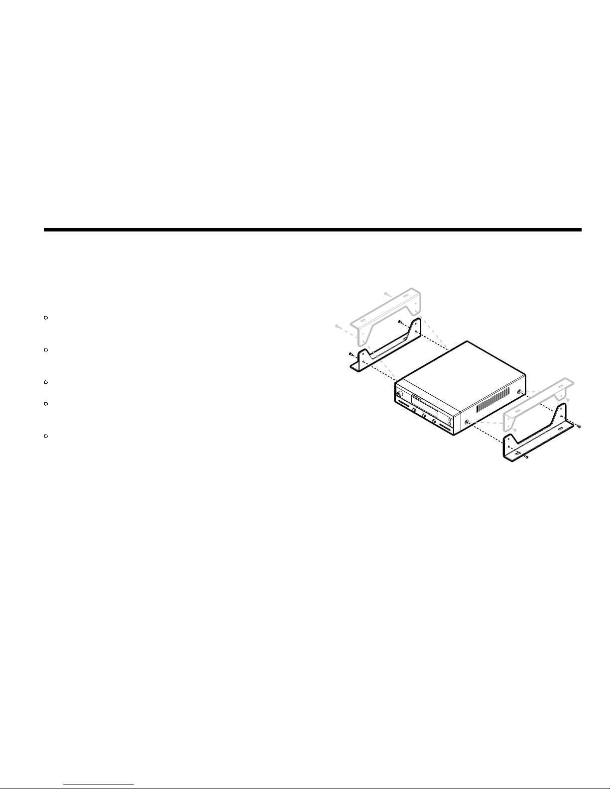
Installing the ACU
Figure 14: Installation of ACU
Selection of Installation site
• The ACU should be installed using the two supplied Table Mounting
Brackets which allow for a top or bottom mounting conguration.
• Using the self tapping screws supplied, attach the mounting brackets
to the sides of the ACU.
• Place the ACU in the location where it is going to be installed.
• Using a pencil to mark the 4 hole positions (2 each side), and use the
appropriate drill bit to drill them.
• Connect the cables to the rear of the ACU.

18
Intellian Satellite TV Antenna Systems
Figure 15: Basic Conguration
Up to 4 Receivers
In Universal LNB mode, RF1, RF2, RF3 and RF4 can be connected.
However, when you use the system from universal LNB mode (ex.
Europe) to single LNB mode (ex. US), RF3 and RF4 will not work and
only RF1 and RF2 will transfer the satellite signal.
ACU
RF 1
RF 3
RF 4
RF 2
Satellite Receiver 2 (IRD)
9-30V DC Power NMEA GPS PC Cable
Satellite Receiver 4 (IRD)
Satellite Receiver 3 (IRD)
Satellite Receiver 1 (IRD)
NMEA
ANT RF1 RECEIVER
FUSEDC 9 - 30 V PC INTERFACE
FG - +
+ -

19
Figure 16: Multi-Receiver
Connecting the System Using a Multi-Switch
When you use the multi-switch in single LNB mode, you need to connect
RF1 and RF2 to the low-band (Horizontal Low and Vertical Low) outputs
of the 4x8 multi-switch and disable DisEqC function while connecting to
a receiver other than a European receiver. In Universal LNB mode, RF1~
RF4 can be connected to any 4 outputs of 4x8 multi-switch. However
when you use the system for single LNB mode, RF3 and RF4 ports will
not transfer the RF signal.
18V 13V 18+22KHz 13V+22KHz
Horiazontal Low Vertical Low Horizontal High Vertical High
ACU
RF 1
RF 3 RF 4
RF 2
Satellite Receiver 8 (IRD)
9-30V DC Power NMEA GPS PC Cable
Satellite Receiver 1 (IRD)
NMEA
ANT RF1 RECEIVER
FUSEDC 9 - 30 V PC INTERFACE
FG - +
+ -
4x8 Multi switch
VL HL VH HH

20
Intellian Satellite TV Antenna Systems
Your satellite TV system has a built-in GPS. If the internal GPS doesn’t
operate properly, you can directly connect your boat’s NMEA 0183 GPS
to the system through the ACU’s external GPS connector. To do this you
will need a suitable cable to connect your GPS system and the green
2-way ACU GPS connector supplied with your Intellian i6W Satellite TV
System.
Connecting the system to a GPS
1. Strip back the insulation of each conductor and connect each terminal
of the 2-way connector.
2. Tighten the locking screws.
3. Connect the +ve (positive) terminal of the ACU GPS connector to the
NMEA OUT wire of the boat’s GPS system.
4. Connect the –ve (negative) terminal of the ACU GPS connector to the
ground wire of the boat’s GPS system.
5. Ret the ACU GPS connector to the rear of the ACU.
NMEA
ANT RF1 RECEIVER
FUSEDC 9 - 30 V PC INTERFACE
FG - +
+ -
GROUND (-)NMEA OUT (+)
Figure : GPS Connection
Other manuals for i6W
1
Table of contents
Other Intellian TV Antenna manuals


