Power supply / frequency
Absorbed current
Absorbed power
Max torque
Max lifting force with 200mm diameter
Nominal speed
Nominal torque
Rolling gate shaft standard diameter
Roller shutter flanges diameter
Crown rotation speed (loadless)
Operating ambient temperature
Class protection
Thermal protection
Continuous operating time
Max work cycle
Weight
Insulation class
* 48 and 42mm with supplied adapter
* 220mm with supplied adapter
Vac / Hz
A
W
Nm
kg
Rpm
Nm
mm
mm
Rpm
°C
IP
°C
Minutes
Sec
kg
1A - ADVERTENCIAS
1C - TECHNICAL CHARACTERISTICS
1 - GENERAL DESCRIPTION
This manual has been especially written for use by qualified installation technicians. No information given in this manual can
be considered as being of interest to end users.
Read these instructions carefully before proceeding with the installation, as they provide important information regarding
safety, installation, use and maintenance.
Any use or operation not explicitly provided for in these instructions is not permitted.
Improper use may cause damage and personal injury.
RING is not suitable for use in potentially explosive atmospheres.
2A - PRELIMINARY CHECKS
2 - INSTALLATION
Please keep in mind that automatic rolling gate systems may only be installed by qualified personnel in compliance with the
legislation in force. Make sure that:
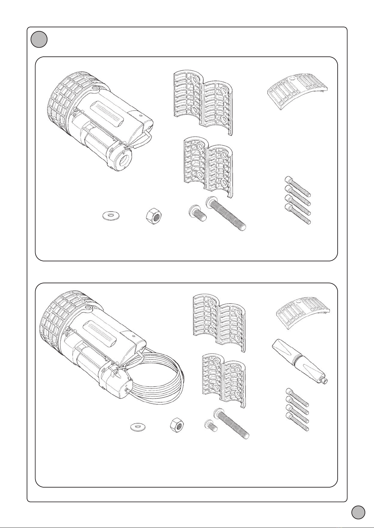
- The packing is undamaged and contains all the parts shown in Fig. 1.
- The rolling gate opens and closes without presenting points of greater friction.
- The rolling gate is well balanced, i.e., if it is stopped in any position it must not display a tendency to start moving again.
- The rolling gate moves silently and smoothly.
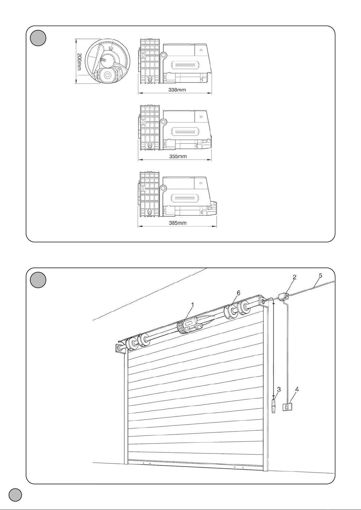
- Refer to Fig. 2 to make sure that the mounting area is compatible with the overall dimensions of the gearmotor.
2B - TYPICAL SYSTEM (FIG. 3)
1 RING gearmotor
2 connector block
3 release knob (only on versions with brake)
4 reverser switch or electronic control unit
5 Power supply line
6 Spring box
2C - MOUNTING
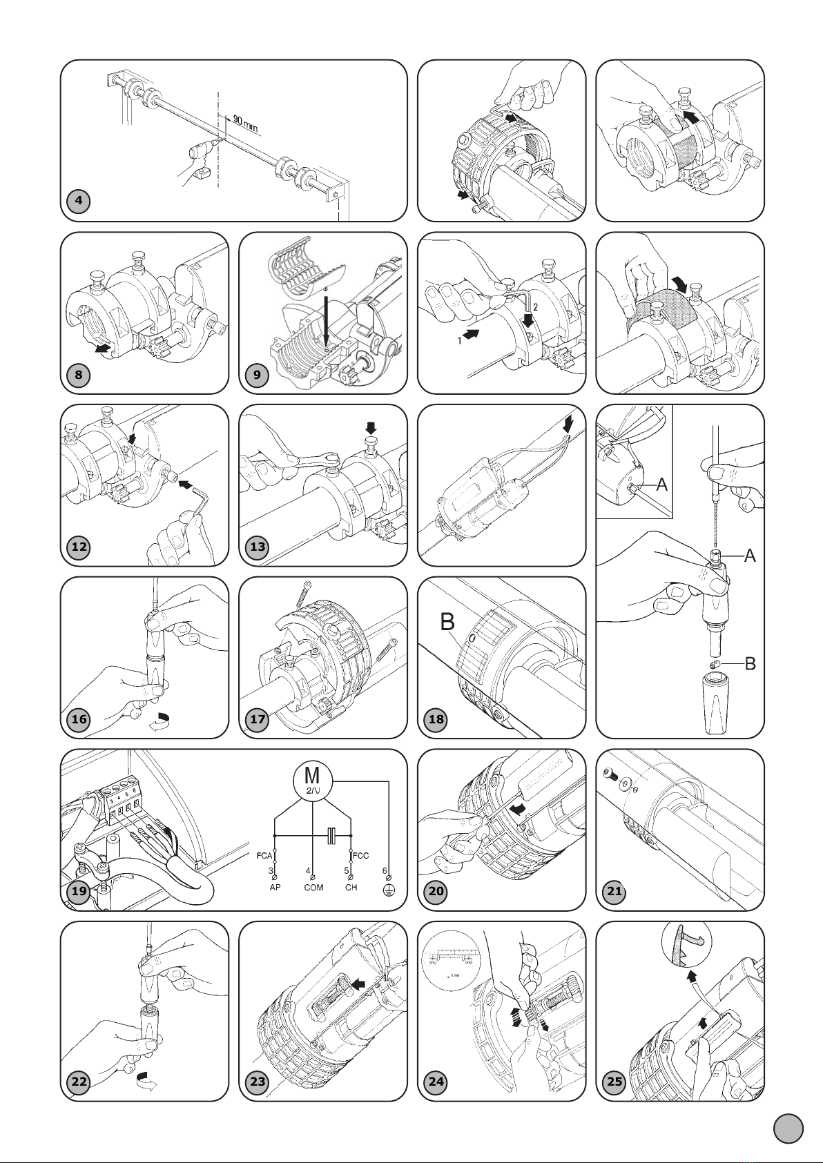
1. Close the rolling gate all the way in order to make the spring shaft accessible and drill an 11mm diameter horizontal hole
90mm from the middle of the spring shaft; Fig. 4
2. Remove the two half ring nuts after loosening the two M8 screws; Fig. 6
3. Remove the slide ring; Fig. 7
4. Slide out the plate in the direction indicated by the arrow; Fig. 8
5. Measure the diameter of the spring shaft. If the diameter of the latter is 60mm, proceed with the installation. If the shaft has
a diameter of 48mm or 42mm, install the adapters provided; Fig. 9
6. Reinstall the plate removed at point 5, paying attention to the direction of assembly, and screw on the four screws provided;
Fig. 10
7. Mount the adapter ring removed at point 4 and grease its outer surface slightly; Fig. 11
8. Insert and tighten the M10 screw; make sure you thread it through the hole drilled in the spring shaft according to the
instructions under point 1; if necessary, use the adapter. Fig. 12
9. Tighten the two M10 screws so as to secure the gearmotor to the spring shaft.
Secure the two screws with lock nuts; Fig. 13
10. Drill a hole in the spring shaft for the power and release wire (only on versions with brake); Fig. 14
11. Assemble the release knob, with all the adjusters tightened (A), insert the wire and, holding it tight, secure it with the
terminal (B). (only on versions with brake); Fig. 15
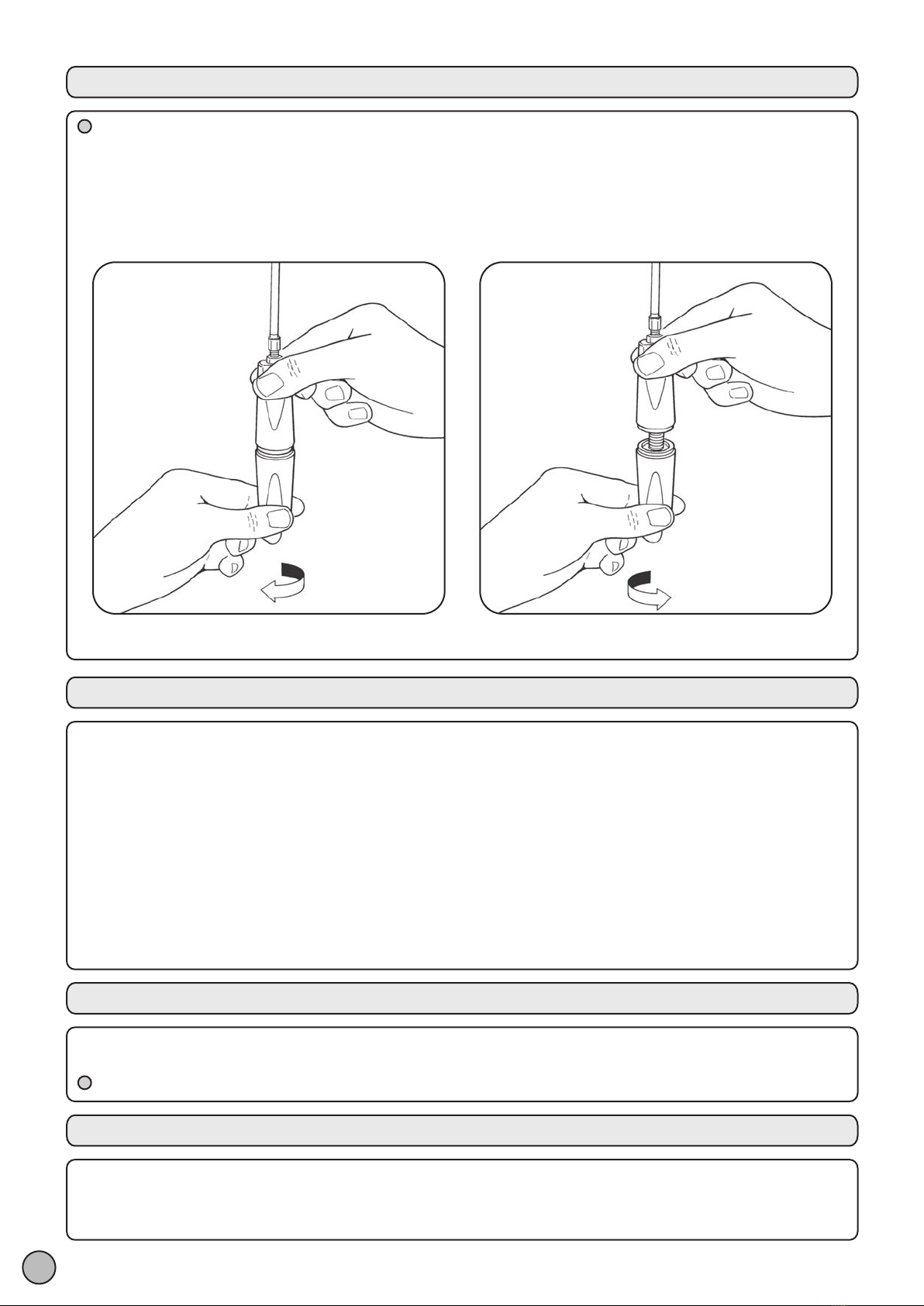
12. Execute the release manoeuvre by turning the bottom knob clockwise to loosen it. Check manually to make sure that the
gearmotor is released. If necessary, operate the adjusters to eliminate any slack; Fig. 16
13. Slightly grease the teeth on the ring gears removed at point 3, then assemble them, tightening
the two M8 screws well; Fig. 17
14. Measure the diameter of the spring boxes. If their diameter is 200mm, proceed with the installation.
15. Otherwise, if the diameter is 220mm, use the appropriate adapter (B); Fig. 18
16. Remove the cover that protects the terminals. Loosen the cable gland. Make the connections Fig. 19. Tighten the cable
gland screws. Close the cover that protects the terminals.
17. Using a screwdriver, remove the glass for the adjustment of the limit switches; Fig. 20
18. Position the last segment of the rolling gate on the half ring nut and drill an 11-mm diameter hole through it to match the
hole in the half ring nut;
19. Tightly fasten the rolling-shutter frame to the gearmotor using screw and washer M10. Fig. 21
20. Release the gearmotor (only on versions with brake) and open and close the rolling gate manually, making sure that it
slides smoothly. Lock the gearmotor again by tightening the release knob; Fig. 22
21. DOWN LIMIT SWITCH ADJUSTMENT (closing)
Using the reverser switch, command the gearmotor to perform a down manoeuvre until the limit switch is triggered.
In the installation illustration, the closing manoeuvre limit switch is the one shown in Fig. 23
22. ADJUSTING THE ASCENT LIMIT SWITCH (opening)
Pull the clip outwards while rotating the wheel indicated by the arrow.
Bear in mind the fact that approximately 1 cm of its travel corresponds to 1 m of upward movement. Release the clip.
Power the gearmotor so it starts rising, and check that the rolling-shutter stops in the position required. Fig. 24.
Continue to make adjustments until you reach the position required;
23. Reinsert the limit switch glass, paying attention to the mounting direction; Fig. 25
24. In case the installation is contrary to the one described, proceed in the reverse order so that the second limit switch will
regulate the down movement, while the first one will regulate the up movement.
1B - PRODUCT DESCRIPTION
RONDO is a gearmotor for spring-balanced rolling gates. It is suitable for the automation of rolling gates having a maximum
height of 6m and weighing up to 180kg.
The gearmotor may be mounted on rolling gates with a spring shaft diameter of 42mm, 48mm and 60mm.
The spring boxes may have a diameter of 200mm / 220mm.
The two ring nuts are made of die-cast aluminium.
The gearmotor is equipped with a micrometric screw stop and mechanical position memory.
RING 150 / RING 180 / RING 150 / 110= Reversible brakeless gearmotor.
RING 150 PLUS / RING 180 PLUS RING 150 / 110 PLUS= Non-reversible gearmotor with brake and release device.
RING 150 / 110
RING 150 / 110
PLUS
RING 180
RING 180 PLUS
RING 150
RING 150 PLUS
2.6
600
60*
200*
-20 ÷ +50
20
140
4
50% with 30s ON and 30s OFF
F
2
450
130
130
75
9.5
180
180
100
230 / 50
8.5
10
120 / 60
4.8
580
10
12
10
2 3