Kingservo KSDG Series User manual

Kingservo
Manual
AC Servo MotorKSMA
Servo Driver KSDG Series
20081014(3rd Version)
汪生:135 1038 2344
QQ:9795 220 98
东莞市京伺自动化设备有限公司
网址:www.kingservo.com
地址:东莞市长安沙头振安中路272号

Contents
Chapter One: Identificaiotns of Products..........................................................5
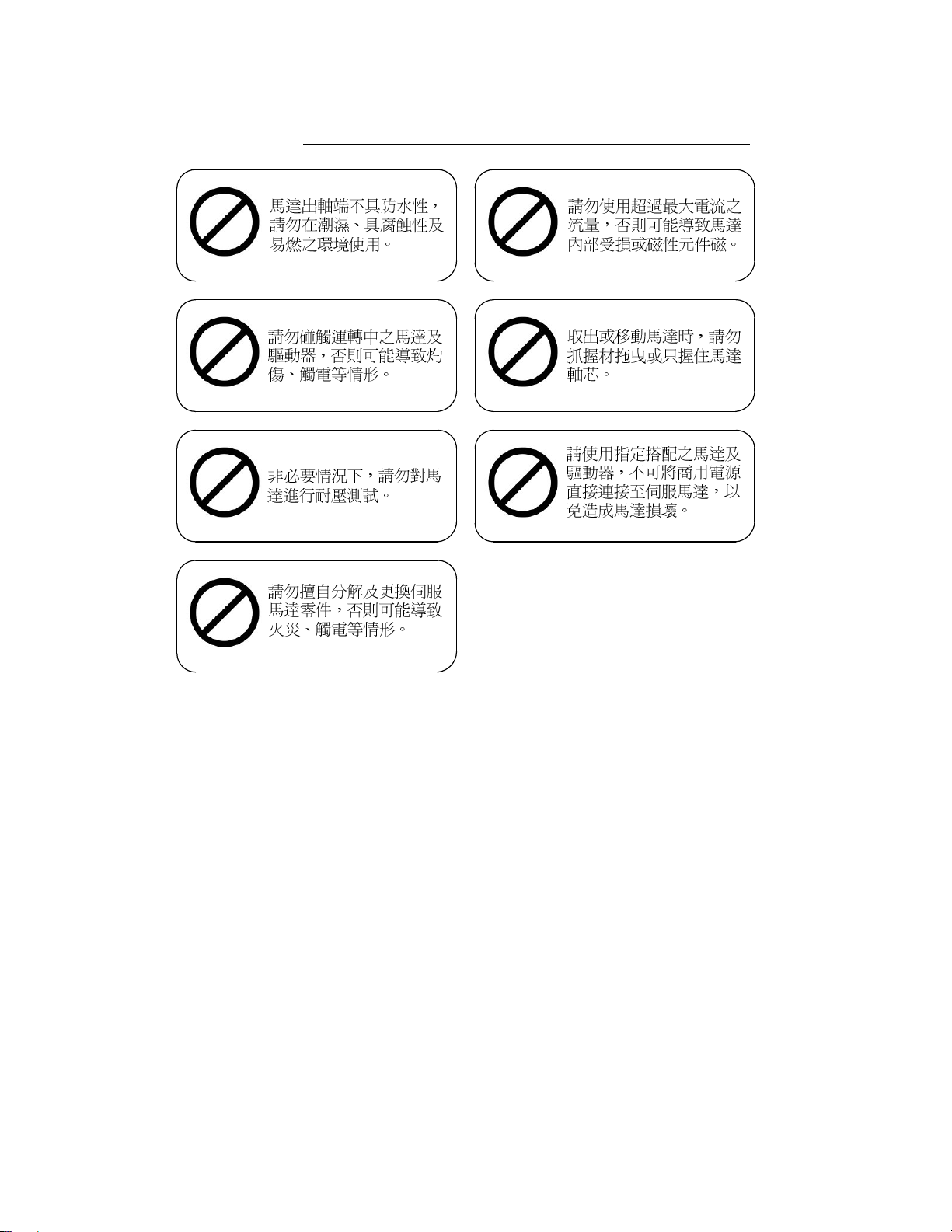
1-1Safety Marking.............................................................................................5
1-2Check before Usage......................................................................................6
1-3 Indentification of AC Servo Driver Type....................................................7
1-3-1 Name-plate of Driver.........................................................................7
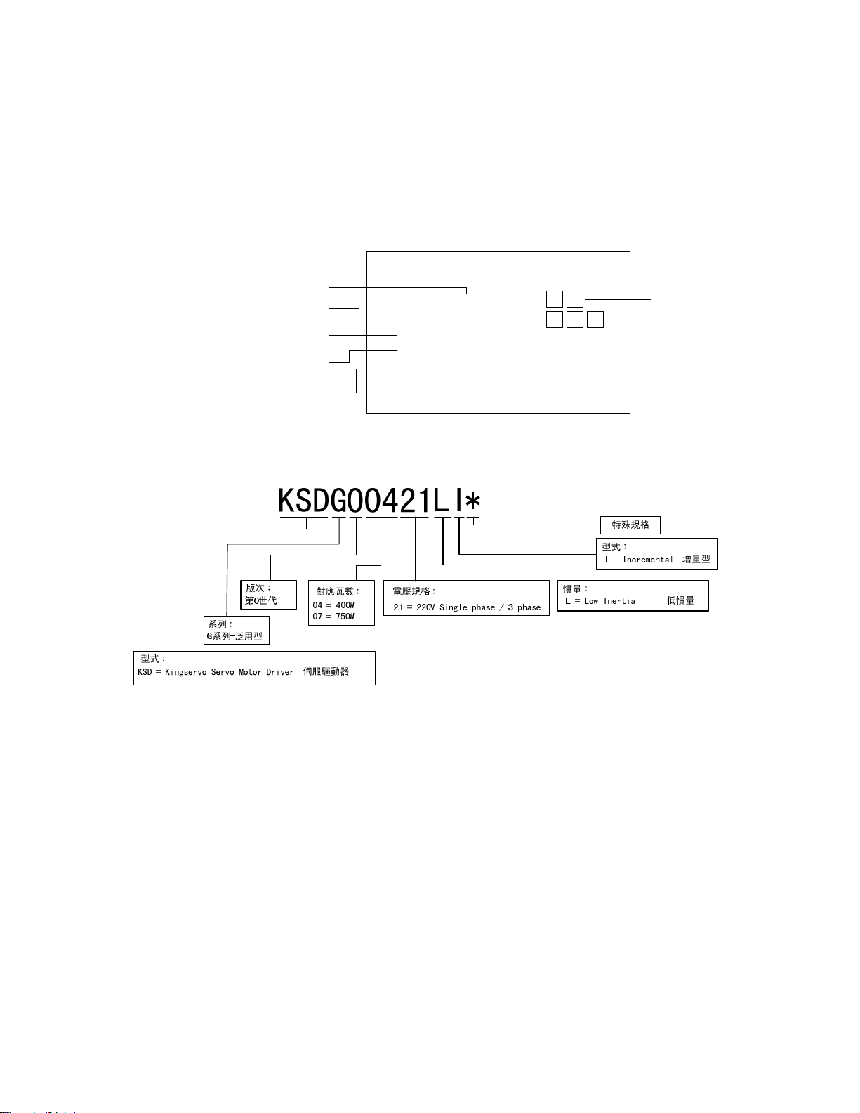
1-3-2 Identificaiton of Driver Type.............................................................7
1-4 Encoding Principles of AC Servo Driver Type...........................................8
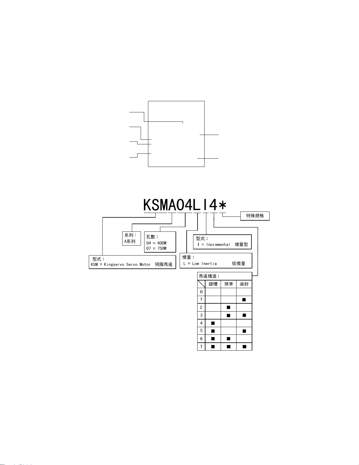
1-4-1Name-plate of Servo Motor.................................................................8
1-4-2 Identification of Servo Motor Type...................................................8
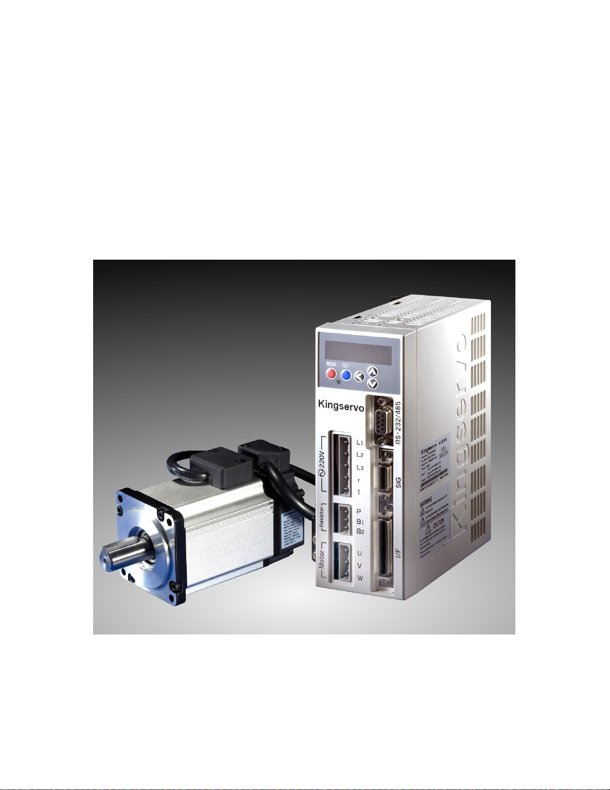
1-5 Names of Parts.............................................................................................9
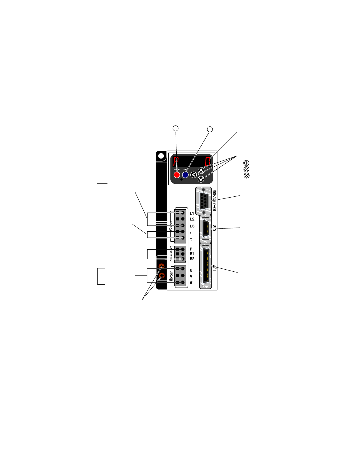
1-5-1Driver..................................................................................................9
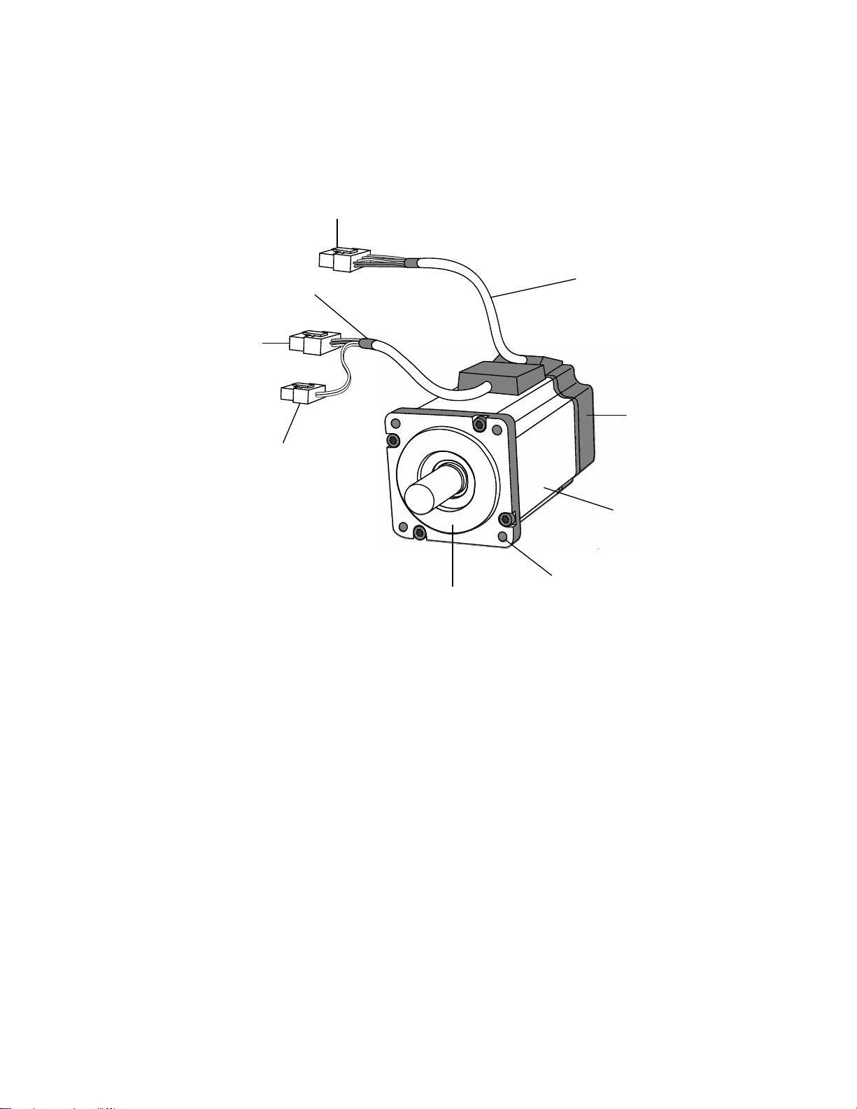
1-5-2 Motor................................................................................................10
1-6 Usage Mode.............................................................................................. 11
Chapter Two: Connectionor and Wiring ....................................................................13
2-1Controller and peripheral configuration map ............................................13
2-2Power wiring diagram................................................................................15
2-3 Defination of Connector Pin.....................................................................17
2-3-1Cable of Encoder...............................................................................17
2-3-2 Power Cable of Motor......................................................................18
2-4 Communication Line of RS-232................................................................19
2-5 Wiring of Connector I/F............................................................................20
2-5-1 Pins of Connector I/F(SCSI II)...... ..................................................21
2-5-2 Signal Modes of Pins........................................................................22
2-5-3 Wiring Diagram of Controlling Mode.............................................23
Chapter Three: Panel Operation .................................................................................27
3-1 Panel Structure..........................................................................................27
3-2 Mode Category and Contents....................................................................28
3-3 Monitoring Modes.....................................................................................29
3-4 Parameters Setting Modes.........................................................................35
3-5 Writing-in Mode of EEPROM..................................................................37
3-5-1 Writing-in Mode of EEPROM .......................... .............................37
3-5-2 Default Writing-in Values of EEPROM .................... ....................38
3-6 Rigid Setting Mode ...................................................................................39
3-7 Auxilary Fuction Mode ............................................................................40
3-7-1Test Run............................................................................................40
3-7-2 Clearance of Abnomality Warning..................................................42

3-7-3 Auto OFFSET Adustment................................................................43
3-7-4 Clearance of Anomaly Record.........................................................44
Chapter Four Parameters .............................................................................................45
4-1 Setting of Parameters and Modes..............................................................45
4-1-1 Introduction of Paramters.................................................................45
4-1-2 Setting Mothed ................................................................................45
4-1-3 Connection Mothed .........................................................................45
4-1-4 Contents and list of Parameters........................................................46
4-2 Funciton Instruciton of Parameters............................................................51
Chapter Fiver: Usage of Pins of Control Mode...........................................................89
5-1 Pins Table of Position, Speed and Torsion Modes....................................89
5-2 Wiring Reference of Interface Lines.........................................................90
5-2-1 Wiring Reference of Input Loop......................................................90
5-2-2 Wiring Reference of Output Loop...................................................92
5-3 Function of Pins of Connector I/F.............................................................94
5-3-1 Input Interface(Sharing):.................................................................94
5-3-2 Input Interface(Pulse):....................................................................98
5-3-3 Input Interface(Analog Command):.............................................100
5-3-4 Output Interface(Sharing):...........................................................102
Chapter Six: Documenets..........................................................................................105
6-1 Dimension Drawing................................................................................105
6-2 Sequential Charter...................................................................................107
6-3 Gain Adjustment..................................................................................... 111
6-4 S-T Feature of Motor.............................................................................. 112
6-5 Feature of Overload Time Limit............................................................. 112
6-6 Connector Group of Connector and Transmission Line......................... 113
6-6-1 Air Connector ............................................................................... 113
6-6-2 Specification of SCSI-II Connector............................................. 113
6-6-3 Specification of Main Loop Connector........................................ 113
6-7 Specificaiton of Driver .......................................................................... 114
6-7-1 Basic Specificaiton........................................................................ 114
6-7-2 Funciton ........................................................................................115

KingServo 4

KingServo 5
Chapter One: Identificaiotns of Products
1-1Safety Sign
Warning Sign

KingServo 6
Inhibition Sign
1-2 Check before Usage
After unpackage, verify:
・Check whether the numbers of parts are as same as the specification?
・Check whether there is any damage to the appearance during
transportation?
Verify whether driver motor controller and motor are the Kingservo Ac Servo
series?
package contents:
・motor
・key slot
・encoding line
・power line
・controllor
・connector
・operation handle of connector

KingServo 7
1-3 Indentification of AC Servo Driver
Type
1-3-1 Name-plate of Driver
Kingservo AC SERVO
Model No : KSDG00421LI
Power : 400W
200~255 3PH 50/60Hz 2.8
200~255 1PH 50/60Hz 3.5
Output : 110V 3PH 0/416.6Hz 2.8
Serial No. : K080401010129
Kingservo Technology CO., LTD. Made In Taiwan
Input : {
PN : BEC-D0801151-00
K080128A- 0001
G D
004
機種名
序號
額定功率
輸入電壓/電流
輸出電壓/相數/頻率/電流
韌體版本
1-3-2 Identifications of Driver Type

KingServo 8
1-4 AC Encoding Principles of Servo
Motor Type
1-4-1 Name-plate of Servo Motor
Kingservo
AC SERVO MOTOR
Input : 3PH C 90V 2.8
Rated Output : 0.4 KW
Rated Freq. : 250 Hz
Rated Rev. : 3000 r/min
CONT.TORQUE : 1.3 Nm
CONNECTION : Y
SER.No. : K080401010165
PN : BEC-M0801151-00
Model No. : KSM 04LI4
機種名
額定電壓/電流
額定輸出
額定轉速
序號
額定扭力
1-4-2 Identification of Servo Motor Type

KingServo 9
1-5 Name of Parts
1-5-1Driver
●KSMG 400W‧750W
顯示用LED(6位)
資料設定按鈕
:SHIFT
:UP
:DOWN
通信用接頭
RS-232
編碼器
連接接頭
SIG
Kingservo
上層控制器
連接接頭
I/F
設定按鈕
SET
模式切換按鈕
MODE
接地連結螺絲
(2個位置)
馬達連結端子
(U,V,W)
231-203/026-000
WAGO
外接回升電阻
連結端子
(P,B1,B2)
控制用電源
連結端子
(r,t)
主電源
連結端子
(L1,L2,L3)
231-103/026-000
WAGO
231-205/026-000
WAGO

KingServo 10
1-5-2 Motor
●KSMA 400W‧750W
螺絲定位孔 (4個)
馬達外殼
旋轉編碼器
編碼器電纜
馬達動力電纜
煞車電纜接頭
(僅現有電磁煞車之馬達)
凸緣
馬達動力電纜接頭
編碼器電纜接頭

KingServo 11
1-6 Usage
1. Usage Modes:
Choose one of following modes. Mode selection must be determined
through I/F connector(MDR) wiring.
Mode Mode Name
Location Control
Speed Control
Single Mode
Torque Control
Location and Speed Control
Location and Torque Control
Mixed Mode
Speed and Torque Control
2. I/F Signal Connection Line
1. connect main power line(L1, L2, L3), control power(r, t), flyback
resistor(P, B1, B2), connector of encoder line(SIG) and power line of
motor(U, V, W) in accordance with connection of peripheral devices of
controller and controller wiring diagram.
2. Increase I/F connector(MDR) wiring and connect them by
·connection of single mode
·connection of all signal pins
Connecting another terminal of upper-level controller to set up
parameters of control mode, and then operate.
About the function definition of I/F pin mode, adjust parameter Pro2 to
contol mode function of PIN14, 6, and 18.
Speed and torque mode control use few pin. Wile single application, the
numbers of I/F Pin Weld line.
3. While I/f connector(MDR) does not connect controller, the motor can be
test run.

KingServo 12
30.0
3.0
8.0
ø50h7
ø14.0
-0.01
-0.00
104.8
60.0
44.0
ø70.0
4 ø4.5
25.0
22.5
5h9
5.011.0
軸端規格

KingServo 13
Chapter Two: Connectionor and Wiring
2-1Controller and peripheral configuration map
L1
L2
L3
r
t
電源雜訊濾波器
電源雜訊濾波器電源雜訊濾波器
電源雜訊濾波器(
((
(NF
NFNF
NF)
))
)
避免因電源線傳來的雜訊。
以及降低從驅動器出來的雜訊。
無熔絲斷路器
無熔絲斷路器無熔絲斷路器
無熔絲斷路器(
((
(NFB
NFBNFB
NFB)
))
)
用於保護電源電路。
當超過額定電流時立刻切斷迴路。
220Vac
三相或單相
端子
端子端子
端子Resistor P
Resistor PResistor P
Resistor P、
、、
、B
BB
B1
11
1、
、、
、B
BB
B2
22
2
通常B1-B2之間是維持在短路狀態。
內建回生電阻容量不足時,請取出
B1-B2之間的短路線,將外接回升電
阻連接在P-B2的端子。
外接回升電阻時,驅動器的參數Pr6C
請設定為1或2。
回生電阻
回生電阻回生電阻
回生電阻
(
((
(另購
另購另購
另購)
))
)
●
●●
●主回路的配線
主回路的配線主回路的配線
主回路的配線
電磁接觸器
電磁接觸器電磁接觸器
電磁接觸器(
((
(MC
MCMC
MC)
))
)
開啟/關閉驅動器的主電源。
嚴禁使用電磁接觸器啟動或停止馬達。
P
B2

KingServo 14
個人電腦 (客戶自備)
(與上層控制器連結)
到RS-232(與個人電腦連結)
編碼器用中繼電纜
(與編碼器連結)
煞車用直流電源
DC24V
(客戶自備)
煞車用
中繼電纜
馬達用中繼電纜
(馬達驅動的各相及接地)

KingServo 15
2-2 Power Wiring Diagram
While alarm system is activated, the main line power should be power off
immediately.
r
t
P
B1
L3
L2
B2
U
W
V
11
2
3
4 4
3
2
驅
動
器
馬達
L1
R
Encode
紅
白
黑
Encode
NF
SIG
I/F RS-232
綠
NFB MC
電源
供應
DC
24V 煞車用直流電源
電源 單相200V~260V
172159-1
Tyco Electronics AMP
172167-1
主電源
控制電源
連結馬達
r
t
P
B1
L3
L2
B2
U
W
V
11
2
3
4 4
3
2
驅
動
器
馬達
L1
R
Encode
紅
白
黑
Encode
NF
SIG
I/F RS-232
綠
NFB MC
電源
供應
DC
24V 煞車用直流電源
電源 單相200V~260V
172159-1
Tyco Electronics AMP
172167-1
主電源
控制電源
連結馬達

KingServo 16
■Function of Flyback Resistor
·While load with large inertia reducing speed, flyback energy leads to rising of driver’s capacitor voltage,
so the flyback resistor is used to absorb and consume the excessive energy and protect driver.
·While using vertical ascending (Z axis) mechanism, flyback problem shall be payed attention to.
·specification of built-in flyback resistor: 150Ωand 50W.
■Application of Built-in Flyback Resistor
·Keep short curicuit between B1 and B2.
·Set parameter Par 6C as 0 (default value is 0).
■Application of External Flyback Resistor
·Connect P and B2 to external flyback resistor(150Ω).
· Set Parameter Par 6C as 1.
The power consumption of external resistor is limited to 10% duty, and set Par 6C as 2.
(while Par 6C is set as 2, overheating-protection fuse shall be installed, or else it may cause overheating
and burning-down of flyback resistor.).

KingServo 17
2-3 Defination of Connector Pin
2-3-1Cable of Encoder
Air Connector
15 PIN
SCSI II Connector
20 PIN
NO. 1
2 3 4 5 6 7-10
11
12
13 14 15
Pin Definition
A
/A
B /B Z /Z
NC
RX
/RX
VCC GND FG
Color Red
Green
Black
White
Yellow
Blue
Gray
Orange
Brown/
Light RED
Purple/
Ligth Green
Grounding Line
of Isolation Net
NO. 1 2 3 4 5-6
7 8 9 10
Pin Definition GND GND VCC VCC
NC
A /A B /B
Color Purple
Light Green Brown
Pink
Red
Green
Black
White
NO. 11 12 13-16
17 18 19 20
Pin Definition Z /Z NC RX /RX NC
GND
Color Yellow Blue
Gray
Orange
Grounding line of
Isolation Net

KingServo 18
Wiring Diagram of Encoder Line
+5V
0V
A
A
B
B
Z
Z
RX
RX
+5V
0V
A
A
B
B
Z
Z
RX
RX
FG
FG
+5V
0V
13
14
20
3
1
4
2
17
18
8
7
9
10
11
12
15
12
11
1
2
3
4
5
6
驅動器 +5V
驅動器 0V
馬達 驅動器側編碼器中繼電纜馬達側
Tyco Electronics AMP
172171-1
Tyco Electronics AMP
172163-1
低慣量750W以下編碼器配線圖
2-3-2 Power Cable of Motor
Pin NO. Definition
Color
1 U Red
2 V White
3 W Black
4 FG Green

KingServo 19
2-4 Communication Line of RS-232
While connecting computer and driver by RS-232, the communication software
KSDTools can be set up. KSDTools provides many convenient functions such
as to monitor the states of motor, set/modify parameters and so no.
2
3
5
2
3
5
Tx
Rx
GND
1
5
6
9
1
5
6
9
Driver PC

KingServo 20
2-5 Wiring of Connector I/F
控制
裝置
電源
馬達
3m以內
30cm以上
與上層控制器等週邊裝置的配線請在3m以內。
與主線路配線需保持30cm以上的距離。通過同
一線槽請勿綁在一起。
請自行準備COM+~COM-之間的控制訊號用電源
(VDC)。電壓:DC+12~+24V。
命令脈波輸入、編碼器訊號輸出等的配線,請
使用有遮蔽的對絞線。
控制訊號輸出端子切勿施加超過24V以上的
電壓,或導通超過50mA以上的電流。
利用控制訊號輸出直接驅動繼電器時,請依
照圖的方向和繼電器並聯一二極體。
如未安裝,或安裝方向錯誤,將導致驅動器
受損。
接地端子已在驅動器內部與地線連接。
1
2
GND
I/F
FG
COM+
COM-
VDC
This manual suits for next models
1
Table of contents
Popular Servo Drive manuals by other brands

Engel
Engel HFI2230-S200 operating manual

SEW-Eurodrive
SEW-Eurodrive MOVITRAC LTX Addendum to the operating instructions

Rockwell Automation
Rockwell Automation Allen-Bradley Ultra3000 Migration guide

Siemens
Siemens SINAMICS V90 operating manual

Technosoft
Technosoft iPOS3602 MX-CAN Technical reference

Cowlacious Designs
Cowlacious Designs Scary Terry ST-400 Operation manual

Arcus
Arcus TITAN-SVX Software manual

LS ELECTRIC
LS ELECTRIC iX7NH Series quick start guide

Siemens
Siemens SINAMICS S200 Compact operating instructions

Nidec
Nidec Control Techniques Digitax-SF Series instruction manual

Copley Controls
Copley Controls Xenus XTL Series manual

Baldor
Baldor MotiFlex e100 installation manual