SERVICE INFORMATION SRM-2305
SRM-2305SI
2
1 SERVICE INFORMATION
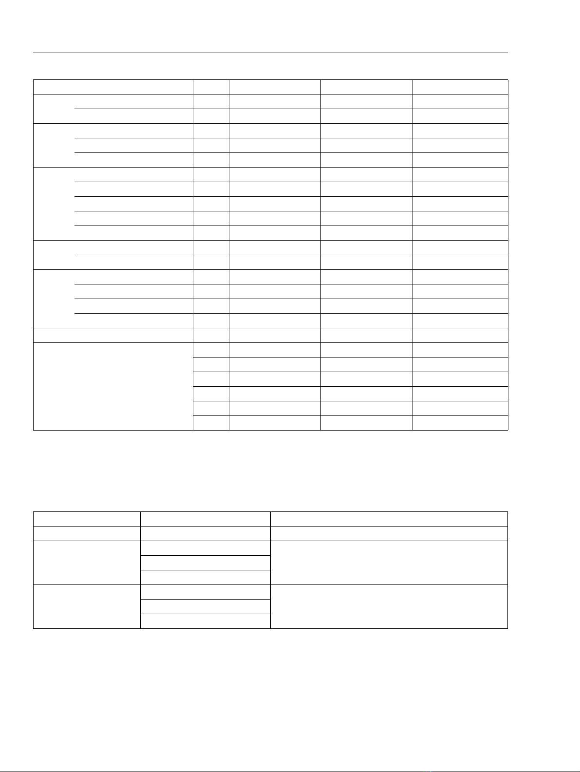
1-1 Specifications
Model
SRM-2305 (L) SRM-2305 (U) SRM-2305SI(L) SRM-2305SI(U)
Dimensions Length* mm(in) 1755 (69.1) 1760 (69.3) 1785 (70.3) 1790 (70.5)
Width mm(in) 355 (14.0) 690 (27.2) 355 (14.0) 690 (27.2)
Height mm(in) 340 (13.4) 455 (17.9) 340 (13.4) 455 (17.9)
Dry weight** kg(lb) 5.6 (12.3) 6.0 (13.2) 5.8 (12.8) 6.2 (13.7)
Engine Type KIORITZ, air-cooled, two-stroke, single cylinder
Rotation Anticlockwise as viewed from the output end
Displacement cm3(in3) 21.2 (1.294)
Bore mm(in) 32.2 (1.268)
Stroke mm(in) 26.0 (1.024)
Compression ratio 6.8
Carburettor Type Diaphragm, horizontal-draught, with primer (purge bulb)
Model ZAMA C1U-K53B
Venturi size-Throttle bore mm(in) 8.5 - 12.7 (0.33 - 1/2)
Ignition Type CDI (Capacitor discharge ignition) system
Spark plug BPMR7A
Starter Type Automatic rewind -start
Rope diameter x length mm(in) 3.0 x 1000 (0.12 x 39.4) 3.0 x 920 (0.12 x 36.2)
Fuel Type Premixed two-stroke fuel
Mixture ratio 50 : 1 (2 %)
Petrol Minimum 89 octane petrol (RON)
Two-stroke air cooled engine oil ISO-L-EGD (ISO/CD13738), JASO FC
Tank capacity L (U.S.fl.oz.) 0.4 (13.5)
Clutch Type Centrifugal, 2 - shoe slide
Handle Type Front Slant D-Loop U-shaped Slant D-Loop U-shaped
Rear Integrated control - - - Integrated control - - -
grip w/cushion grip w/cushion
Drive shaft Type Solid
Inner shaft: Diameter - Length mm(in) 6 - 1538 (0.24 - 60.6)
Housing OD -ID mm(in) 25 - 22 (0.98 -0.87)
(Main pipe) Length mm(in) 1500 (59.1)
Gear case Reduction ratio 1.36
Gear tooth Spiral bevel gear
Lubrication Lithium based grease
Cutter Type Nylon line cutter, 3-tooth blade†, Others
Pilot diameter mm(in) 25.4 (1.0)
Fastener type, size mm Left-hand thread nut, M10 x 1.25 pitch
Cutting rotation Anticlockwise as viewed from top
OD: Outer diameter. ID: Inner diameter.
* Without shoulder harness and cutter head. ** With standard cutter head, without shoulder harness.
† Install and use U-shaped handle when operating with steel blade.