Kioto Solar GK10 User manual

DE Handbuch
EN
I
F
E
Manual
Manuale
Manuel
Manual
60°
45°
30°
25-75°
GK10 / GK5


3
30° 60°
45° 25-75°
Sicherheitshinweise..................................................... 5
Montagehinweise ...................................................... 6
Betriebsempfehlungen................................................... 8
WartungAntireflexglas .................................................. 9
Transporthinweis...................................................... 30
Auflagekräfte........................................................ 33
AngabenzumKollektor ................................................. 35
Empfehlung für Befestigungspunkte ........................................ 37
Materialübersicht ..................................................... 38
Werkzeugübersicht.................................................... 40
Betonballastmontage-30/45/60 .......................................... 41
Aufdachmontagesystem, parallel........................................... 52
Mögliche Durchströmungsarten............................................ 54
Druckverlust......................................................... 55
Allgemeine Nutzungshinweise............................................. 56
Konformitätserklärung . . . . . . ............................................ 57
Inhaltsverzeichnis
Contents
Indice
Table des matières
Contenido
Avvertenzeperlasicurezza .............................................. 15
Istruzionidimontaggio ................................................. 16
Istruzionidimontaggio ................................................. 17
Consigliperlamessainfunzione .......................................... 18
Manutenzionevetroantiriflesso ........................................... 19
IndicazioniperilTrasporto............................................... 30
Forze d‘appoggio...................................................... 33
InformazionisulCollettore............................................... 35
Raccomandazioneperipuntidifissaggio..................................... 37
Panoramicadeimateriali................................................ 38
Panoramicadegliutensili................................................ 40
Montaggiozavorreincemento-30/45/60 ................................... 41
Sistema di montaggio su tetto, in parallelo.................................... 52
Possibili tipi di flusso ................................................... 54
Flussocollettore...................................................... 55
Avvertenze generali per l’utilizzo. . . . . . ..................................... 56
Dichiarazionediconformità .............................................. 57
Safety information .................................................... 10
Assemblyinstructions.................................................. 11
Operating tips........................................................ 13
Maintenance of anti-reflective glass......................................... 14
Transportnote ....................................................... 30
Load pressure........................................................ 33
Information about the collector............................................ 35
Recommendation for attachment points...................................... 37
Overviewofmaterials.................................................. 38
Overviewoftools ..................................................... 40
Concreteballastassembly-30/45/60....................................... 41
On-roofmountingsystem,parallel ......................................... 52
Possibleflowtypes .................................................... 54
Flow-through........................................................ 55
GeneralUsageInstructions .............................................. 56
Declarationofconformity................................................ 57
DE
EN
IT
DE EN IT FR ES

4
30° 60°
45° 25-75°
Inhaltsverzeichnis
Contents
Indice
Table des matières
Contenido
Instructionsdesécurité................................................. 20
Instructionsdemontage ................................................ 21
Recommandations d’emploi .............................................. 23
Entretienduverreantireflets............................................. 24
Indicationspourletransport ............................................. 30
Forcesd‘appui ....................................................... 33
Indicationsportantsurlecapteur.......................................... 35
Recommandation concernant les points de fixation . ............................. 37
Vued’ensembledumatériel.............................................. 38
Vued’ensembledesoutils ............................................... 40
Montagedeblocsdelestenbéton-30/45/60................................. 41
Système de montage sur toiture en parallèle .................................. 52
Typesd’écoulementpossibles............................................. 54
Traverséedufluide.................................................... 55
Consignes générales d’utilisation........................................... 56
Déclarationdeconformité ............................................... 57
Advertenciasdeseguridad............................................... 25
Instruccionesdemontaje................................................ 26
Recomendacionesparaelfuncionamiento .................................... 28
Mantenimiento del cristal antirreflejo........................................ 29
Indicaciones para el Transporte............................................ 30
Fuerzasdeapoyo..................................................... 33
Datosdelcolector..................................................... 35
Recomendacionesparalospuntosdefijación.................................. 37
Vistageneraldelosmateriales............................................ 38
Vistageneraldelasherramientas.......................................... 40
Montajedelacargadehormigón-30/45/60.................................. 41
Sistemademontajesobretejadoenparalelo.................................. 52
Tipos de circulación posibles.............................................. 54
Pérdidadepresión .................................................... 55
Instruccionesgeneralesdeuso............................................ 56
Declaracióndeconformidad.............................................. 57
FR
ES
DE EN IT FR ES
6903178.1 / version 2016-11

5
30° 60°
45° 25-75° Sicherheitshinweise
Safety information
Avvertenze per la sicurezza
Instructions de sécurité
Advertencias de seguridad
DE
Bei Dachmontagen vorschriftsmäßige personenunabhängi-
ge Absturzsicherungen oder Auffangeinrichtungen nach DIN
18338 Dachdeckungs- u. Dachdichtungsarbeiten und nach
DIN 18451 Gerüst- arbeiten mit Sicherheitsnetz unbedingt
vor Arbeits- beginn aufbauen! Bauarbeiterschutz-Verord-
QXQJ%*%/6RQVWLJHOlQGHUVSH]L¿VFKH
Vorschriften sind unbedingt einzuhalten!
Sicherheitsgeschirr möglichst oberhalb des Benutzers an-
schlagen. Sicherheitsgeschirr nur an tragfähigen Bauteilen
bzw. Anschlagpunkten befestigen!
Falls personenunabhängige Absturzsicherungen oder
Auffangvorrichtungen aus arbeitstechnischen Gründen nicht
vorhanden sind, sind Sicherheitsgeschirre zu verwenden!
Schadhafte Leitern nicht benutzen, z.B. angebrochene
Holme und Sprossen von Holzleitern, verbogene und an-
geknickte Metallleitern. Angebrochene Holme, Wangen und
6SURVVHQYRQ+RO]OHLWHUQQLFKWÀLFNHQ
Nur von autorisierten Prüfstellen gekennzeichnete und ge-
prüfte Sicherheitsgeschirre (Halte- oder Auffanggurte, Ver-
bindungsseile/bänder, Falldämpfer, Seilkürzer) verwenden.
Anlegeleiter sicher aufstellen. Richtigen Auf- stellungswin-
kel beachten (68 ° - 75 °). Anlegeleitern gegen Ausgleiten,
Umfallen, Abrutschen und Einsinken sichern, z.B. durch
Fußverbreiterungen, dem Untergrund angepasste Leiterfü-
ße, Einhänge- vorrichtungen.
Falls keine personenunabhängige Absturzsicherungen oder
Auffangvorrichtungen vorhanden sind, kann es ohne Benut-
zung von Sicherheitsgeschirren zu Abstürzen aus großen
Höhen und damit zu schweren oder tödlichen Verletzungen
kommen!
Leitern nur an sichere Stützpunkte anlehnen. Leitern im
Verkehrsbereich durch Absperrungen sichern.
Bei Verwendung von Anlegeleitern kann es zu gefährlichen
Stürzen kommen, wenn die Leiter einsinkt, wegrutscht oder
umfällt!
Das Berühren spannungsführender, elektrischer Freileitun-
gen kann tödliche Folgen haben.
In der Nähe spannungsführender, elektrischer Freileitungen,
bei denen ein Berühren möglich ist, nur arbeiten, wenn
– deren spannungsfreier Zustand hergestellt und für die
Dauer der Arbeit sichergestellt ist.
– die spannungsführenden Teile durch Abdecken oder
Anschranken geschützt sind.
– die Sicherheitsabstände nicht unterschritten werden.
Spannungsradius:
1 m bei .........................1000 Volt Spannung
3 m bei ..........1000 bis 11000 Volt Spannung
4 m bei ........11000 bis 22000 Volt Spannung
5 m bei ........22000 bis 38000 Volt Spannung
> 5 m bei unbekannter Spannungsgröße
Bei Bohrarbeiten und beim Hantieren mit Solarkollektoren
(Glasbruch) Schutzbrille tragen!
Bei Montage Sicherheitsschuhe tragen!
Bei der Kollektormontage und beim Hantieren Kollektoren
schnittsichere Arbeitshandschuhe tragen!
Es darf nur das vorgeschriebene Wärmeträgermedium
eingesetzt werden! Bei Montage Helm tragen!

6
30° 60°
45° 25-75°
Montagehinweise
Assembly instructions
Istruzioni di montaggio
Instructions de montage
Instrucciones de montaje
DE
Allgemeine - und Transporthinweise
Die Montage darf nur von fachkundigen Personen vorgenommen werden. Ausschließlich an solche fachkundigen
Per-sonen richten sich sämtliche Ausführungen dieser Anleitung. Grundsätzlich ist zur Montage das mitgelieferte
Materialzu verwenden. Informieren Sie sich vor der Montage und dem Betrieb der Sonnenkollektoranlage über die
M
HZHLOVJOWLJHQ|UWOLFKHQ1RUPHQXQG9RUVFKULIWHQ=XP7UDQVSRUWGHV.ROOHNWRUVHPS¿HKOWVLFKGLH9HUZHQGXQJ
eines Mon-tagekrans. Der Kollektor ist nur an den vormontierten Kranösen hochzuheben und darf nicht an den An-
VFKOVVHQKRFKJHKREHQZHUGHQ9HUPHLGHQ6LH6W|HXQGPHFKDQLVFKH(LQÀVVHDXIGHQ.ROOHNWRULQVEHVRQGHUHDXI
Solarglas,Kollektorrückwand und Rohranschlüsse.
Statik
'LH0RQWDJHGDUIQXUDXIDXVUHLFKHQGWUDJIlKLJHQ'DFKÀlFKHQE]Z8QWHUNRQVWUXNWLRQHQHUIROJHQ'LHVWDWLVFKH7UDJ
fähigkeit des Daches bzw. der Unterkonstruktion ist vor der Montage der Kollektoren bauseits, allenfalls durch Beizie-
hung eines Statikers auf örtliche und regionale Gegebenheiten unbedingt zu prüfen. Dabei ist besonderes Augenmerk
auf die Güte des Unterbaus bezüglich der Haltbarkeit von Schraubverbindungen zur Befestigung von Kollektormonta-
gevorrichtungen zu legen. Die bauseitige Überprüfung des gesamten Kollektoraufbaues gemäß DIN 1055 Teil 4 und 5
(17HLOXQGE]ZJHPlGHQOlQGHUVSH]L¿VFKJHOWHQGHQ9RUVFKULIWHQLVWEHVRQGHUVLQVFKQHHUHLFKHQ*H
bieten (Hinweis: 1 m³ Pulverschnee ~ 60 kg / 1 m³ Nassschnee ~ 200 kg) bzw. in Gebieten mit hohen Windgeschwin-
GLJNHLWHQHUIRUGHUOLFKVLHKH7DEHOOHÄ$XÀDJHUHDNWLRQHQ³'DEHLLVWDXFKDXIDOOH%HVRQGHUKHLWHQGHV$XIVWHOOXQJVRUWHV
(Föhn, Düseneffekte, Wirbelbildung, etc.) einzugehen, welche zu erhöhter Belastung führen können. Grundsätzlich
sind Kollektorfelder so zu montieren, dass ev. möglicher Schneerückstau durch Schneefanggitter (oder durch beson-
GHUH$XIVWHOOXQJVVLWXDWLRQHQGLH.ROOHNWRUHQQLFKWHUUHLFKW'HU$EVWDQG]X'DFK¿UVWHQUlQGHUQPXVV]XPLQGHVWP
betragen.
Hinweis: Die Montage eines Kollektorfeldes ist ein Eingriff in ein (bestehendes) Dach, besonders ausgebaute und
bewohnte Dachgeschosse bzw. unterschrittene Mindestdachneigungen erfordern (bezogen auf die Eindeckung) - als
Sicherheit gegen das Eindringen von Wasser durch Winddruck und Flugschnee zusätzliche, bauseitige Maßnahmen
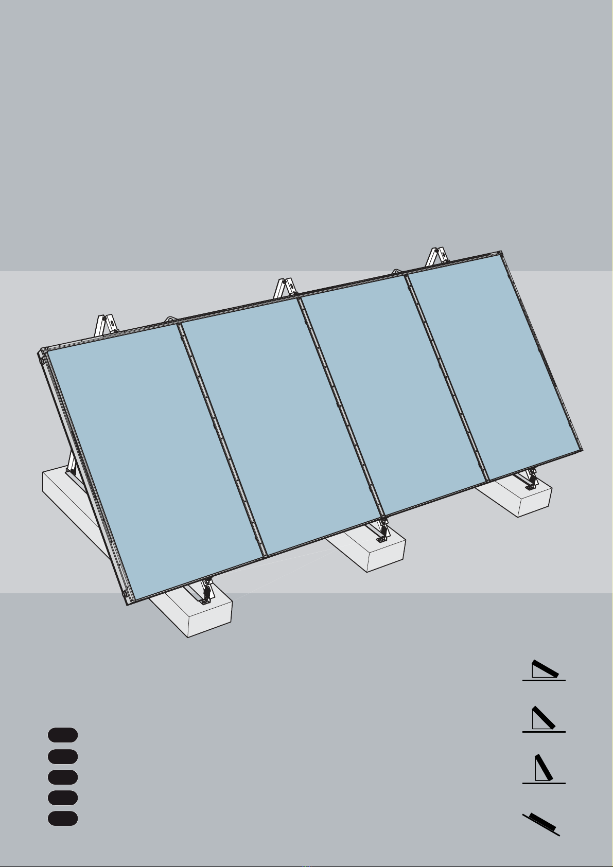
wie z. B. Unterspannbahnen. Für größere Kollektorfelder wird empfohlen, die Kollektoren auf eine eigene Tragekon-
VWUXNWLRQDXV6WDKOSUR¿OHQ]XPRQWLHUHQ'LH%HIHVWLJXQJVYDULDQWHPLWWHOV%HWRQEDOODVWEO|FNHQXQG6HLOYHUVSDQQXQ
gen ermöglicht eine Montage ohne Durchdringung der Dachhaut. Die Kollektoren werden auf Betonblöcke montiert.
Um die Haftreibung zwischen Dach und Betonballastblöcken zu erhöhen sowie um Beschädigungen der Dachhaut zu
vermeiden, sind gegebenenfalls Gummiunterlagsmatten zu verwenden. Werden die Dimensionen der Betonballast-
blöcke entsprechend der unten angeführten Tabelle eingehalten, ist keine zusätzliche Absicherung mittels Stahlseilen
notwendig. Falls das Gesamtgewicht (Gesamtgewichte der Betonballastblöcke und maximal mögliche Schneelast) die
statische Tragbarkeit der Unterkonstruktion überschreiten, so kann eine Kombination aus leichteren Betonballastblö-
cken plus zusätzlicher 5 mm starken Stahlseilen (Mindestzugfestigkeit 1450 N/mm²) zur Sicherung verwendet werden.
Werden Betonballäste verwendet deren Gewicht unter den in obiger Tabelle
geforderten Angaben liegen, ist eine Absicherung mit Stahlseilen
(5 mm / Mindestzugfestigkeit 1450 N/mm²) erforderlich!
Befestigungsausführung: DIN 1055 Teil 4 und 5 / EN 1991-1 Teil 4 und 5
-> „High Load“ (HL): 3 kN/m² Schnee, 150 km/h Wind
-> „Standard Load“ (SL): 1,25 kN/m² Schnee, 150 km/h Wind
Tabelle: Betonballastdimensionen in Abhängigkeit der Windlast
Betonballäste
Dimensionen/Gewichte je Stützenpaar
'LH*HZLFKWVDQJDEHQGHU%DOODVWEO|FNHJHOWHQXQWHUGHU$QQDKPHHLQHV5HLEXQJVNRHI¿]LHQWHQYRQ
(Beton auf Beton im trockenen Zustand)
Windlast
[km/h]
30° 45° 60°
L/B/H [m] kg L/B/H [m] kg L/B/H [m] kg
100 2,40 x 0,30 x 0,17 295 2,40 x 0,30 x 0,21 365 2,40 x 0,30 x 0,30 520
150 2,40 x 0,30 x 0,46 795 2,40 x 0,30 x 0,48 830 2,40 x 0,30 x 0,72 1245

7
30° 60°
45° 25-75°
Blitzschutz / Gebäudepotentialausgleich
Gemäß der aktuellen Blitzschutznorm ÖVE/ÖNORM EN 62305 Teil 1-4 darf das Kollektorfeld nicht an den Gebäude-
blitzschutz angeschlossen werden. Ein Sicherheitsabstand von mindestens 1 m zu einem möglichem benachbartem,
leitendem Objekt ist einzuhalten. Bei Montagen auf bauseitigen Unterkonstruktionen aus Metall sind generell befugte
Elektrofachkräfte zu konsultieren. Um einen Gebäudepotentialausgleich durchzuführen, müssen die metallischen Rohr-
leiter des Solarkreises sowie alle Kollektorgehäuse bzw. Befestigungen gemäß ÖVE/ÖNORM E 8001-1 bzw. den länder-
VSH]L¿VFKHQ1RUPHQPLWGHU+DXSWSRWHQWLDODXVJOHLFKVVFKLHQHGXUFKHLQHEHIXJWH(OHNWURIDFKNUDIWYHUEXQGHQZHUGHQ
Anschlüsse (Schraubverbindungen)
'LH.ROOHNWRUHQVLQGPLWYLHUYHUVFKUDXEEDUHQ$QVFKOVVHQó³$*DXVJHVWDWWHWXQGXQWHUHLQDQGHUE]ZPLWGHU
6\VWHP$QVFKOXVVYHUURKUXQJÀDFKGLFKWHQG]XYHUELQGHQ$XINRUUHNWHQ6LW]GHU)ODFKGLFKWXQJHQLVW]XDFKWHQ$OV
Verbindungselemente zwischen den Kollektoren sind Längenkompensatoren zu verwenden, um die Längenausdeh-
nungen der Kupferrohre bei Temperaturschwankungen zu kompensieren. Unter der Voraussetzung, dass die Län-
genkompensatoren verwendet werden, können bis zu 11 Kollektoren in einer Reihe verschaltet werden (ACHTUNG:
Überprüfung der Pumpenauslegung bzw. der Strömungsdifferenzen in den einzelnen Kollektoren). Beim Anziehen der
Anschlüsse mit dem Schraubenschlüssel sollte ein Drehmoment von 30 Nm nicht überschritten werden, damit die
Sammelleitung bzw. der Absorber nicht beschädigt wird.
Kollektorneigung - Allgemeines
Die Kollektorbefestigungssysteme sind für die Montagevarianten 30 °, 45 ° und 60 ° ausgelegt. Die Kollektoren sind
für eine Neigung von minimal 25 ° und maximal 75 ° geeignet! Die Kollektoranschlüsse und die Be-/ Entlüftungsöff-
nungen sind vor Wassereintritt sowie vor Verschmutzungen wie Staubeintrag, etc. zu schützen.
Gewährleistung
Gewährleistungsanspruch nur in Verbindung mit Original-Frostschutz des Lieferanten und ordnungsgemäß durch-
geführter Wartung. Einbau durch fachkundige Personen in ausnahmsloser Befolgung der Montageanleitung zur An-
spruchsbegründung vorausgesetzt.
Fühlermontage
Die Fühlertauchhülse ist am Solar Vorlauf, d.h. am oberen Sammelrohr beim letzten in der Reihe geschalteten Kollek-
tor zu montieren. Bei mehreren Kollektorreihen, die in einem Kreislauf zusammengefasst sind, ist die Fühlertauchhülse
am Solar Vorlauf, d.h. am oberen Sammelrohr beim letzten, in der von der Pumpe am weitest entferntesten Reihe
geschalteten, Kollektor zu montieren.
DE
Montagehinweise
Assembly instructions
Istruzioni di montaggio
Instructions de montage
Instrucciones de montaje

8
30° 60°
45° 25-75°
Betriebsempfehlungen
Operating tips
Consigli per la messa in funzione
Recommandations d’emploi
Recomendaciones para el funcionamiento
DE
Spülung und Befüllung
Aus Sicherheitsgründen ist die Füllung ausschließlich während Zeiten ohne Sonneneinstrahlung oder mit abge-
deckten Kollektoren durchzuführen. Insbesondere in frostgefährdeten Gebieten ist die Verwendung von bis zu
40%-igem Frostschutz-Wasser-Gemisch notwendig. Um die Materialien vor übermäßiger thermischer Belastung
zu schützen, sollte eine Befüllung und Inbetriebnahme der Anlage möglichst kurzfristig, längstens aber nach 4
Wochen erfolgen. Ist dies nicht möglich, sollten die Flachdichtungen vor der Inbetriebnahme erneuert werden,
um Undichtheiten vorzubeugen.
Nicht vorgemischter Frostschutz muss vor dem Einfüllen mit Wasser gemischt werden!
Empfohlene Frostschutzmittel für Flachkollektoren: TYFOCOR-L
40 % FS-Anteil (60%/Wasser) - Gefrierpunkt: - 22 ° C / Stockpunkt: - 26 ° C
50 % FS-Anteil (50%/Wasser) - Gefrierpunkt: - 32 ° C / Stockpunkt: - 44 ° C
Es ist möglich, dass einmal befüllte Kollektoren nicht mehr vollständig entleert werden können. Deshalb dürfen
Kollektoren bei Frostgefahr auch für Druckproben und Funktionstests nur mit Wasser/Frostschutzgemisch befüllt
werden. Alternativ kann die Druckprobe mit Druckluft und Lecksuchspray durchgeführt werden.
Betriebsdruck
Der maximale Betriebsdruck beträgt 10 bar.
Entlüften
Eine Entlüftung muss durchgeführt werden:
– bei Inbetriebnahme (nach dem Befüllen)
– 4 Wochen nach der Inbetriebnahme
– bei Bedarf, z.B. Störungen
9HUEUKXQJVJHIDKUGXUFK'DPSIE]ZKHLH:lUPHWUlJHUÀVVLJNHLW
(QWOIWXQJVYHQWLOQXUEHWlWLJHQZHQQGLH7HPSHUDWXUGHU:lUPHWUlJHUÀVVLJNHLW&LVW
Beim Entleeren der Anlage dürfen die Kollektoren nicht heiß sein! Kollektoren abdecken und Anlage möglichst
morgens entleeren.
:lUPHWUlJHUÀVVLJNHLWSUIHQ
'LH:lUPHWUlJHUÀVVLJNHLWPXVVDOOH-DKUHDXI)URVWVFKXW]XQGS+:HUWEHUSUIWZHUGHQ
– Frostschutz mittels Frostschutzprüfer prüfen und gegebenenfalls tauschen bzw. nachfüllen!
Sollwert ca. - 25 ° C bis - 30 ° C bzw. je nach klimatischen Gegebenheiten.
– pH-Wert mit einem pH-Indikatorstäbchen prüfen (Sollwert ca. pH 7,5):
%HL8QWHUVFKUHLWHQGHV*UHQ]S+:HUWHVYRQS+GLH:lUPHWUlJHUÀVVLJNHLWWDXVFKHQ
Wartung des Kollektors
Der Kollektor bzw. das Kollektorfeld ist jährlich durch eine optische Kontrolle auf div. Schäden, Dichtheit und
9HUVFKPXW]XQJHQ]XSUIHQ1DFKGHU(UVWLQEHWULHEQDKPHXQGLQ-DKUHV]HLWHQPLWVWDUNHQ$XHQWHPSHUD
turschwankungen kann es zu Kondensatbildung im Kollektor kommen. Dieser Beschlag löst sich jedoch nach
einigen Stunden Sonnenbestrahlung auf.

9
30° 60°
45° 25-75°
:DUWXQJ$QWLUHÀH[JODV$5*ODV
8PHLQHRSWLPDOH/HLVWXQJGHV.ROOHNWRUVPLWWUDQVPLVVLRQVHUK|KWHP*ODV$QWL5HÀH[*ODVNXU]$5*ODV
zu erzielen und aufrecht zu erhalten, sollten insbesondere nachstehende Punkte beachtet werden.
Verwenden Sie …
– saubere Hebezeuge, Saughalter und Handschuhe
– einen Überzug für die Vakuumglasheber (Material: Tyvek) und erneuern Sie diesen bei Verschmutzung
–GLH*ODVREHUÀlFKHQLFKWDOV$EODJHIU0RQWDJHPDWHULDOLHQRGHU6RQVWLJHV
Reinigen Sie das AR-Glas …
– mit klarem Wasser oder einer milden Seifenlauge
1DFKIROJHQGH3XQNWHIKUHQ]X%HVFKlGLJXQJHQGHU$QWLUHÀH[%HVFKLFKWXQJXQGYHUPLQGHUQ
dadurch den Leistungsertrag des Kollektors!
Vermeiden Sie …
– Fingerabdrücke oder Flecken am Glas
– die Verwendung von Lederhandschuhen
–GHQ.RQWDNWPLW6LOLNRQgO)HWWRGHUDQGHUHU]lKÀVVLJHUK\GURSKREHU6XEVWDQ]HQ
– Hilfsmittel zur Reinigung wie Autopolitur, Flusssäure, Stahlwolle, Drahtbürste, Polierleinen,
– Scheuerpulver und Stoffe welche Metallgarn im Gewebe enthalten
– mechanische Reinigungsmethoden wie Schrubben, Abstreifen oder Hochdruckreinigung
H2O
Glass
No stretchfoil
Glass
:DUWXQJ$QWLUHÀH[JODV
0DLQWHQDQFHRIDQWLUHÀHFWLYHJODVV
0DQXWHQ]LRQHYHWURDQWLULÀHVVR
(QWUHWLHQGXYHUUHDQWLUHÀHWV
0DQWHQLPLHQWRGHOFULVWDODQWLUUHÀHMR
DE

10
30° 60°
45° 25-75°
Sicherheitshinweise
Safety information
Avvertenze per la sicurezza
Instructions de sécurité
Advertencias de seguridad
EN
Safety precautions: Before commencing mounting
work on roofs, it must be ensured in all cases that
the non- personal fall protection and fall-arrest
systems required by DIN 18338 (Roof Covering and
Roof Sealing Works) and DIN 18451 (Scaffolding
Works) are in place. See also Builders‘ Protection
Ordinance [Bauarbeiterschutzverordnung], Federal
Law Gazette 340/ 1994, paragraphs 7-10! Other
FRXQWU\VSHFL¿FUHJXODWLRQVPXVWEHREVHUYHG
6DIHW\KDUQHVVHVVKRXOGEH¿[HGDERYHWKHXVHUV
whenever possible. Safety harnesses should only be
IDVWHQHGWRVXI¿FLHQWO\ORDGEHDULQJVWUXFWXUHVRU
¿[LQJSRLQWV
If non-personal fall protection or fall-arrest systems
cannot be installed for technical reasons, all per-
sonnel must be secured by means of suitable safety
harnesses!
Never use damaged ladders (e.g., wooden ladders
with split runners or rungs, or bent or buckled metal
ladders). Never try to repair broken runners, rungs
or steps on wooden ladders!
Only use safety harnesses (safety belts, lanyards
and straps, shock absorbers, fall arresters) that
ZHUHWHVWHGDQGFHUWL¿HGE\DXWKRUL]HGWHVWLQJ
bodies.
Ensure that ladders are put up safely. Observe the
correct leaning angle (68° - 75°). Prevent ladders
from sliding, falling over or sinking into the ground
(e.g. using wider feet, feet suited to the ground or
hooking devices).
If non-personal fall protection or fall-arrest systems
are not provided, working without the use of suita-
ble safety harnesses may lead to falls from heights
and therefore cause serious or lethal injuries!
Only lean ladders against secure points. Secure
ODGGHUVLQWUDI¿FDUHDVE\VXLWDEOHFRUGRQLQJ
Ladders not properly secured against sinking in,
sliding or falling over may lead to dangerous falls! Contact with live electric overhead cables can be
lethal.
Whenever you are near live overhead electric cables
where contact is possible, only work if:
–it is ensured that they are voltage-free and this
is secured for the duration of work.
–the live parts are secured by covering them or
cordoning them off.
–the prescribed safety distances are maintained.
Voltage radius:
1 m ................voltages up to 1000V
3 m ................voltages from 1000V to 11000V
4 m ................voltages from 11000V to 22000V
5 m ................voltages from 22000V to 38000V
> 5 m in case of unknown voltages
Wear protective goggles when drilling and handling
collectors!
Wear safety shoes when carrying out installation
work!
Wear cut-proof safety gloves when mounting
collectors!
2QO\WKHKHDWWUDQVIHUPHGLXPVSHFL¿HGPD\EHXVHG Wear a helmet when carrying out installation work!

11
30° 60°
45° 25-75° Montagehinweise
Assembly instructions
Istruzioni di montaggio
Instructions de montage
Instrucciones de montaje
EN
General and transport instructions
,QVWDOODWLRQPXVWRQO\EHFDUULHGRXWE\TXDOL¿HGSHUVRQQHO7KHHQWLUHLQIRUPDWLRQLQWKHVHLQVWUXFWLRQVLVLQWHQGHG
H[FOXVLYHO\IRUVXFKTXDOL¿HGSHUVRQQHO2QO\WKHVXSSOLHGPDWHULDOVKRXOGEHXVHGIRUWKHLQVWDOODWLRQ3ULRUWRVWDUWLQJ
installation and operation of the solar collector system, please inform yourself about the applicable local standards and
regulations. We recommend using an assembly crane for transporting the collector. The collector must only be lifted
YLDWKHSUHPRXQWHGOLIWLQJULQJVDQGPXVWQRWEHOLIWHGDWWKHFRQQHFWLRQV$YRLGLPSDFWVDQGPHFKDQLFDOLQÀXHQFHV
on the collector, in particular on the solar glass, the collector rear panel and pipe connections.
Statics
7
KHFROOHFWRUVPD\RQO\EHPRXQWHGRQVXI¿FLHQWO\ORDGEHDULQJURRIVXUIDFHVDQGVXEVWUXFWXUHV,WLVLPSHUDWLYHWKDW
the static load bearing capacity of the roof or substructure is checked in terms of local and regional conditions prior to
installation of the collectors by the customer, if necessary through the involvement of a structural engineer. Particular
attention should be paid to the quality of the substructure in terms of the stability of the screw connections necessary
for fastening the collectors. The checking of the entire collector structure by the customer as per EN 1991-1 part 4
DQGRUDVSHUWKHDSSOLFDEOHFRXQWU\VSHFL¿FUHJXODWLRQVLVSDUWLFXODUO\LPSRUWDQWLQDUHDVZLWKKHDY\VQRZIDOOQRWH
1m³ powder snow ~ 60kg / 1m³ wet snow ~ 200kg) or in areas exposed to high wind speeds (see table „Reactions to
UHTXLUHPHQWV³7KHDVVHVVPHQWVKRXOGDOVRWDNHLQWRDFFRXQWDQ\SDUWLFXODUFLUFXPVWDQFHVDWWKHSODFHRILQVWDOODWLRQ
(foehn wind, air jets or eddy formation etc.) which can lead to increased loads. As a rule, collector arrays must be ins-
talled such that any possible collection of snow is prevented from reaching the collectors by snow barriers (or through
special forms of installation). The distance to roof ridges/edges must be at least 1m.
Note: The installation of a collector array is an intervention into a (existing) roof; above all, converted and inhabited
loft spaces or roofs with less than the minimum slope (with regards to the covering) require additional measures by
the customer, e.g. sarking membranes, as protection against the penetration of water through wind pressure and dri-
ving snow. With larger collector arrays, we recommend installing the collectors on a special supporting structure made
of steel channels. Alternatively, it is possible to install the collectors without perforating the roof membrane by using
concrete ballast with guys. The collectors are mounted on concrete blocks. Rubber mats should be used if necessary
to protect the roof membrane against damage and to increase the friction between the roof and the ballast blocks. If
the dimensions of the concrete ballast blocks are adhered to as per the table below, no additional securing through
steel cables is required. If the total weight (total weight of the concrete ballast blocks and maximum possible snow
load) exceeds the static load bearing capacity of the substructure, a combination of lighter concrete ballast blocks plus
additional 5 mm steel cables (minimum tensile strength 1450N/mm²) can be used for securing.
If concrete ballast is used whose weight is below that given in the
table above, additional securing with steel cables
(5mm / min. tensile strength 1450N/mm²) is required!
Mountingset: EN 1991-1 part 4 and 5
-> „High Load“ (HL): 3kN/m² snow, 150km/h wind
-> „Standard Load“ (SL): 1,25kN/m² snow, 150km/h wind
Table:
Concrete ballast dimensions dependent on wind load
Concrete ballasts
Dimensions/weight per support pair
7KHZHLJKWVSHFL¿FDWLRQVRIWKHEDOODVWEORFNVDSSO\XQGHUWKHDVVXPSWLRQRIDIULFWLRQFRHI¿FLHQWRI
(concrete on concrete in dry condition)
wind load
[km/h]
30° 45° 60°
L/B/H [m] kg L/B/H [m] kg L/B/H [m] kg
100 2,40 x 0,30 x 0,17 295 2,40 x 0,30 x 0,21 365 2,40 x 0,30 x 0,30 520
150 2,40 x 0,30 x 0,46 795 2,40 x 0,30 x 0,48 830 2,40 x 0,30 x 0,72 1245

12
30° 60°
45° 25-75°
Montagehinweise
Assembly instructions
Istruzioni di montaggio
Instructions de montage
Instrucciones de montaje
EN
Lightning protection / Equipotential bonding o
f
the building
$VSHUWKHVWLSXODWLRQVRI/LJKWQLQJ3URWHFWLRQ6WDQGDUG(13DUWVWRWKHFROOHFWRU¿HOGPXVWQRWEHFRQ
QHFWHGWRWKHEXLOGLQJµVOLJKWQLQJSURWHFWLRQ%H\RQGWKHVFRSHRIYDOLGLW\RIWKLVVWDQGDUGFRXQWU\VSHFL¿FOHJLVODWLRQ
must be observed. A safety gap of at least 1 m from any adjacent object that may be conductive must be left. In the
FDVHRILQVWDOODWLRQVRQWRSRIH[LVWLQJPHWDOVXEVWUXFWXUHVDQDXWKRULVHGDQGTXDOL¿HGHOHFWULFLDQPXVWEHFRQVXOWHG
T
o enable potential equalisation of the building, the metallic conductor pipes of the solar circuit and all of the collector
KRXVLQJ¿[WXUHVPXVWEHFRQQHFWHGWRWKHPDLQHTXLSRWHQWLDOEXVEDULQDFFRUGDQFHZLWK(1DQGRUFRXQWU\
VSHFL¿FOHJLVODWLRQE\DQDXWKRULVHGDQGTXDOL¿HGHOHFWULFLDQ
Connections
7
KHFROOHFWRUVDUHHTXLSSHGZLWKIRXUVFUHZFRQQHFWLRQVó³PDOHWKUHDGDQGPXVWEHFRQQHFWHGZLWKÀDWVHDOLQJ
WRHDFKRWKHURUWRWKHV\VWHPFRQQHFWLRQSLSHV(QVXUHFRUUHFWSODFHPHQWRIWKHÀDWJDVNHWV/HQJWKFRPSHQVDWRUV
must be used as connection elements between the collectors in order to compensate the length expansion of the
FRSSHUSLSHVGXULQJWHPSHUDWXUHÀXFWXDWLRQV3URYLGHGWKDWWKHOHQJWKFRPSHQVDWRUVDUHXVHGXSWRFROOHFWRUVFDQ
EHFRQQHFWHGLQVHULHV$77(17,21&KHFNWKHSXPSGHVLJQRUWKHÀRZGLIIHUHQFHVLQWKHLQGLYLGXDOFROOHFWRUV:KHQ
tightening the connections with the spanner, a torque of 30Nm should not be exceeded so as to prevent damage to
the manifold or absorber.
Collector angle / General notes
7
KHFROOHFWRU¿[LQJV\VWHPVDUHGHVLJQHGWREHDVVHPEOHGDWDQG7KHFROOHFWRUVDUHVXLWDEOHIRUD
minimum angle of 25° and a maximum angle of 75°! The collector connections and the ventilation openings must be
protected against the penetration of water as well as against contamination through dust etc.
Warranty
Warranty claims can only be made if the supplier‘s own antifreeze has been used and maintenance has been carried
RXWFRUUHFWO\,QVWDOODWLRQE\TXDOL¿HGSHUVRQQHOZLWKDEVROXWHDGKHUHQFHWRWKHLQVWUXFWLRQVLVDSUHUHTXLVLWHIRUWKH
M
XVWL¿FDWLRQRIFODLPV
Installing the sensor
T
he sensor immersion sleeve must be installed on the solar supply, i.e. on the upper manifold of the last collector
connected in the series. If there are several series of collectors which are combined in a circuit, the sensor immersion
sleeve must be installed on the solar supply, i.e. on the upper manifold of the last collector connected in the series
farthest away from the pump.

13
30° 60°
45° 25-75° Betriebsempfehlungen
Operating tips
Consigli per la messa in funzione
Recommandations d’emploi
Recomendaciones para el funcionamiento
EN
Flushing and charging
For safety reasons, charging is to be carried out only when there is no direct sunlight or when the collectors are
covered. Especially in areas liable to freezing, an anti-freeze/water mixture of up to 40% must be used. To pro-
tect materials from excessive thermal load, the system should be charged and commissioned as soon as possi-
EOHDIWHUZHHNVDWWKHODWHVW,IWKLVLVQRWSRVVLEOHWKHÀDQJHVHDOVVKRXOGEHUHQHZHGEHIRUHFRPPLVVLRQLQJ
to prevent leaks.
$QWLIUHH]HWKDWLVQRWSUHPL[HGPXVWEHPL[HGZLWKZDWHUSULRUWR¿OOLQJ
5HFRPPHQGHGDQWLIUHH]HIRUÀDWSODWHFROOHFWRUVTYFOCOR-L
SURSRUWLRQRIDQWLIUHH]HZDWHUIUHH]LQJSRLQW&VROLGL¿FDWLRQSRLQW&
,WPD\QRWEHSRVVLEOHWRFRPSOHWHO\HPSW\FROOHFWRUVRQFHWKH\KDYHEHHQ¿OOHG)RUWKLVUHDVRQFROOHFWRUVH[
SRVHGWRIURVWVKRXOGRQO\EH¿OOHGZLWKDZDWHUDQWLIUHH]HPL[WXUHDOVRIRUSUHVVXUHDQGIXQFWLRQWHVWV$OWHU
natively, the pressure test can also be carried out using compressed air and leak detection spray.
Operating pressure
T
he maximum operating pressure is 10 bar.
Bleeding
T
he system must be bled:
– ZKHQFRPPLVVLRQLQJWKHV\VWHPDIWHU¿OOLQJWKHFROOHFWRUV
– 4 weeks after commissioning
– when necessary, e.g. if there are malfunctions
5LVNRIVFDOGLQJGXHWRVWHDPDQGKRWKHDWWUDQVIHUÀXLG
2QO\RSHUDWHWKHEOHHGLQJYDOYHLIWKHWHPSHUDWXUHRIWKHKHDWWUDQVIHUÀXLGLV&
When bleeding the system, the collectors must not be hot! Cover the collectors and, if possible, bleed the sys-
tem in the morning.
&KHFNKHDWWUDQVIHUÀXLG
7
KHKHDWWUDQVIHUÀXLGPXVWEHFKHFNHGHYHU\WZR\HDUVZLWKUHJDUGWRLWVDQWLIUHH]HDQGS+YDOXH
– &KHFNDQWLIUHH]HXVLQJDQWLIUHH]HWHVWHUDQGUHSODFHRUUH¿OOLIQHFHVVDU\
Target value is ca. - 25° C and - 30° C depending on climatic conditions.
– Check pH value with a pH indicator rod (target value approx. pH 7.5):
,IWKHOLPLWS+YDOXHLVOHVVWKDQS+UHSODFHWKHKHDWWUDQVIHUÀXLG
Maintenance of the collector
T
he collector or the collector array must be inspected visually, once a year, for any damage, leaks and conta-
mination. Condensate can form in the collector after commissioning and during times of the year with strong
RXWGRRUWHPSHUDWXUHÀXFWXDWLRQV7KLVFRQGHQVDWHGLVDSSHDUVKRZHYHUDIWHUDIHZKRXUVH[SRVXUHWRVXQOLJKW

14
30° 60°
45° 25-75°
:DUWXQJ$QWLUHÀH[JODV
0DLQWHQDQFHRIDQWLUHÀHFWLYHJODVV
0DQXWHQ]LRQHYHWURDQWLULÀHVVR
(QWUHWLHQGXYHUUHDQWLUHÀHWV
0DQWHQLPLHQWRGHOFULVWDODQWLUUHÀHMR
EN
0DLQWHQDQFHR
I
DQWLUH
À
HFWLYHJODVV$5JODVV
T
o ensure and preserve the best possible performance of a collector with increased transmission glass (anti-
UHÀHFWLYHJODVVRU$5JODVVIRUVKRUWWKHIROORZLQJSRLQWVLQSDUWLFXODUVKRXOGEHREVHUYHG
Use …
– Clean lifting gear, suction holders, and gloves
– A cover for the glass vacuum lifter (material: Tyvek; replace when dirty)
– Do not use the glass surface as a place to deposit installation material or other objects!
Clear the AR glass …
– With plain water or slightly soapy water
7KHIROORZLQJFDQGDPDJHWKHDQWLUHÀHFWLYHFRDWLQJDQGWKXVSUHYHQWWKH
collector from achieving its full performance!
Avoid …
– *HWWLQJ¿QJHUSULQWVRUVWDLQVRQWKHJODVV
– Using leather gloves
– Contact with silicone, oil, grease, and any other thick, hydrophobic substances
– &OHDQLQJDLGVVXFKDVFDUSROLVKÀXRULFDFLGZLUHZRROZLUHEUXVKHVSROLVKLQJFORWKV
– scouring powder, and fabrics containing metal yarn
– Mechanical cleaning methods such as scrubbing, stripping, and high-pressure cleaning
H2O
Glass
No stretchfoil
Glass

15
30° 60°
45° 25-75° Sicherheitshinweise
Safety information
Avvertenze per la sicurezza
Instructions de sécurité
Advertencias de seguridad
IT
In caso di montaggio sul tetto predisporre neces-
sariamente prima dell’inizio dei lavori dispositivi
anticaduta oppure di salvataggio a norma generici,
come previsto dalla DIN 18338 (Lavori di copertura
e di tenuta del tetto) e dalla DIN 18451 (Lavori su
impalcature con rete di sicurezza)! Ordinamento di
sicurezza del personale edile BGBL 340/ 1994 §7-
5LVSHWWDUHDVVROXWDPHQWHOHQRUPHVSHFL¿FKH
del relativo paese!
Agganciare l’imbracatura di sicurezza possibilmen-
te al di sopra dell’utente. Fissare l’imbracatura di
sicurezza soltanto ad elementi o a punti di aggancio
saldi!
Qualora per motivi tecnici di lavoro non esistessero
dispositivi anticaduta e di salvataggio generici, van-
no adottate imbracature di sicurezza!
Non utilizzare scale danneggiate, ad es. scale in
legno con corrimano e pioli spezzati, oppure scale
di metallo piegate e deformate. Non rappezzare
corrimano, e pioli spezzati di scale di legno!
Adottare soltanto imbracature di sicurezza control-
ODWHHGRWDWHGLPDUFKLRULODVFLDWRGDHQWLXI¿FLDOLGL
controllo (cinture di sostegno e di salvataggio, funi/
fasce di sicurezza, cinture smorzacaduta, accorcia-
funi).
Posizionare le scale da appoggio in modo sicuro.
Rispettare il giusto angolo di appoggio (68 ° - 75
°). Assicurare le scale da appoggio dal pericolo di
scivolamento, di caduta e di affossamento, ad es.
ingrandendone i piedi, adottando piedi idonei alla
VXSHU¿FLHG¶DSSRJJLRXVDQGRGLVSRVLWLYLGLDJJDQ
cio.
Qualora non esistano dispositivi anticaduta e di
salvataggio, la mancata adozione di imbracature
di sicurezza può essere causa di caduta da grandi
altezze con conseguenti lesioni gravi o mortali!
Appoggiare le scale solo a punti di sostegno sicuri.
,Q]RQHGLWUDI¿FRDVVLFXUDUHOHVFDOHPHGLDQWH
sbarramenti.
In caso di impiego di scale da appoggio possono ve-
UL¿FDUVLFDGXWHSHULFRORVHTXDORUDODVFDODVLDIIRVVL
scivoli, o cada.
Il contatto con linee elettriche scoperte in tensione,
può avere conseguenze mortali.
È consentito lavorare nei pressi di linee elettriche
scoperte in tensione, che possono essere anche
toccate, solo se
–manca la tensione e questa condizione è garan-
tita per tutta la durata dei lavori.
–le parti di conduzione della tensione sono protet-
te mediante copertura oppure sbarramento.
–vengono rispettate le distanze di sicurezza.
Raggio di tensione:
1 m ...............con tensione di 1000 Volt
3 m ...............con tensione da 1000 a 11000 Volt
4 m ...............con tensione da 11000 a 22000 Volt
5 m ...............con tensione da 22000 a 38000 Volt
> 5 m con tensione sconosciuta
Durante i lavori di perforazione e maneggiando i
collettori portare gli occhiali protettivi!
Durante il montaggio portare le scarpe di sicurezza!
Durante il montaggio e maneggiando i collettori
portare guanti di sicurezza antitaglio!
8VDUHHVFOXVLYDPHQWHLOÀXLGRWHUPRYHWWRUH
prescritto! Durante il montaggio portare il casco di sicurezza!

16
30° 60°
45° 25-75°
Montagehinweise
Assembly instructions
Istruzioni di montaggio
Instructions de montage
Instrucciones de montaje
IT
Informazioni generali e per il trasporto
L‘installazione deve essere eseguita solo da personale competente. Tutte le versioni del presente documento sono
GHVWLQDWHXQLFDPHQWHDSHUVRQDOHTXDOL¿FDWR'LQRUPDVLUDFFRPDQGDGLXWLOL]]DUHSHULOPRQWDJJLRLOPDWHULDOH
d‘installazione fornito. Prima del montaggio e della messa in esercizio è opportuno informarsi sulle norme e disposi-
zioni del luogo in cui è situato l‘impianto a collettori solari. Per il trasporto del collettore si consiglia l‘impiego di una
gru di montaggio. Il collettore deve essere sollevato solo mediante gli occhielli di sollevamento premontati e non deve
essere sollevato servendosi degli attacchi. Evitate che il collettore subisca urti e azioni meccaniche, proteggete soprat-
tutto il vetro solare, la parete posteriore del collettore e gli attacchi per i tubi.
Statica
,OPRQWDJJLRGHYHDYYHQLUHVROWDQWRVXVXSHU¿FLGLWHWWLRVRWWRVWUXWWXUHVXI¿FLHQWHPHQWHUREXVWL/DFDSDFLWjVWDWLFD
GHOWHWWRRGHOODVRWWRVWUXWWXUDGHYHHVVHUHDVVROXWDPHQWHYHUL¿FDWDVXOSRVWRSULPDGLSURFHGHUHDOPRQWDJJLRGHL
collettori; rivolgersi eventualmente ad un ingegnere strutturista che conosca le caratteristiche locali e regionali del ter-
reno. In questa operazione deve essere attentamente valutata l‘idoneità del legno dell‘intelaiatura riguardo alla tenuta
GHLFROOHJDPHQWLDYLWHSUHGLVSRVWLSHULO¿VVDJJLRGHLFROOHWWRUL/DYHUL¿FDUHDOL]]DWDGDOFRVWUXWWRUHGHOOµLQWHUDLQWHODLD
tura del collettore in base alle norme EN 1991-1 parti 4 e 5 o secondo le norme vigenti nel rispettivo paese è richies-
ta in particolare in zone soggette a forti precipitazioni nevose (nota: 1 m³ di neve farinosa ~ 60 kg / 1 m³ di neve
EDJQDWDaNJRYYHURLQUHJLRQLHVSRVWHDIRUWLYHQWLYHGHUHWDEHOODÄ)RU]HGLDSSRJJLR³,QTXHVWLFDVLRFFRUUH
tener conto di tutte le caratteristiche del luogo di montaggio (föhn, effetto ugello, formazione di vortici, ecc.), che pos-
sono comportare maggiori sollecitazioni. I campi di collettori devono essere assemblati in modo tale da impedire che
DFFXPXOLGLQHYHFDXVDWLGDJULJOLHSDUDQHYHRGDDOWULIDWWRULGRYXWLDOORURSRVL]LRQDPHQWRDUULYLQR¿QRDLFROOHWWRUL
La distanza dai colmi/bordi del tetto deve essere almeno di 1 m.
Nota:LOPRQWDJJLRGLXQFDPSRGLFROOHWWRULFRVWLWXLVFHXQLQWHUYHQWRWDOHGDPRGL¿FDUHODVWUXWWXUDSUHHVLVWHQWHGHO
tetto; in particolare attici aggiunti ed abitati o pendenze minime del tetto inferiori ai valori richiesti (riferiti alla coper-
WXUDULFKLHGRQROµDGR]LRQHGLPLVXUHFRVWUXWWLYHDJJLXQWLYHDWWHDGLPSHGLUHLQ¿OWUD]LRQLGµDFTXDGRYXWHDOODSUHVVL
one del vento e della neve tra cui, ad esempio, la stesura di membrane impermeabilizzanti. Per campi di collettori di
JUDQGLGLPHQVLRQLqFRQVLJOLDELOHPRQWDUHLFROOHWWRULVXXQµDSSRVLWDVWUXWWXUDSRUWDQWHLQSUR¿OLGµDFFLDLR/DYDULDQWH
GL¿VVDJJLRPHGLDQWHEORFFKLGL]DYRUUDLQFHPHQWRHFRUGHSHUPHWWHGLLQVWDOODUHLFROOHWWRULVHQ]DSHUIRUDUHODFRSHU
tura. I collettori vengono assemblati su blocchi di cemento. Per aumentare l‘aderenza fra il tetto e i blocchi di cemento
ed evitare danni alla copertura, si raccomanda l‘impiego di tappetini di gomma. Se i valori riportati nella tabella qui di
seguito per le dimensioni dei blocchi zavorra in cemento vengono rispettati non è necessario provvedere ad un ulteri-
ore ancoraggio mediante funi in acciaio. Se il peso totale (peso totale dei blocchi zavorra in cemento e carico da neve
massimo consentito) eccedesse la capacità statica della sottostruttura, si potrebbe adottare per sicurezza una com-
binazione tra blocchi zavorra in cemento più leggeri e funi in acciaio con un diametro di 5 mm (resistenza minima alla
trazione 1450 N/mm²).
Se vengono utilizzate zavorre in cemento il cui peso è inferiore a quello
indicato nella tabella qui sopra, è necessario utilizzare cavi d‘acciaio di sicurezza
(5 mm / resistenza minima alla trazione 1450 N/mm²)!
(VFX]LRQHGHO¿VVDJJLR(1SDUWLH
-> „High Load“ (HL): 3 kN/m² neve, 150 km/h vento
-> „Standard Load“ (SL): 1,25 kN/m² neve, 150 km/h vento
Tabella: Dimensioni delle zavorre in cemento dipendenti dal carico da vento
Zavorre in cemento
Dimensioni/Pesi per coppia di sostegni
,YDORULGLSHVRGHLEORFFKL]DYRUUDYHQJRQRFDOFRODWLEDVDQGRVLVXXQFRHI¿FLHQWHGLDWWULWRGL
(a cemento su cemento asciutto)
Carico da vento
[km/h]
30° 45° 60°
L/B/H [m] kg L/B/H [m] kg L/B/H [m] kg
100 2,40 x 0,30 x 0,17 295 2,40 x 0,30 x 0,21 365 2,40 x 0,30 x 0,30 520
150 2,40 x 0,30 x 0,46 795 2,40 x 0,30 x 0,48 830 2,40 x 0,30 x 0,72 1245

17
30° 60°
45° 25-75° Montagehinweise
Assembly instructions
Istruzioni di montaggio
Instructions de montage
Instrucciones de montaje
IT
3URWH]LRQHDQWL
I
XOPLQHFRPSHQVD]LRQHGHOSRWHQ]LDOHGHOOµHGL
¿
FLR
In base all‘attuale norma sulla protezione contro i fulmini EN 62305, parte 1-4, il campo di collettori non può essere
FROOHJDWRDOVLVWHPDGLSURWH]LRQHDQWLIXOPLQHGHOOµHGL¿FLR$OGLIXRULGHOOµDPELWRGLDSSOLFD]LRQHGHOODQRUPDFLWDWDYDQ
no rispettate le prescrizioni locali. Mantenere una distanza di sicurezza minima di 1 m da eventuali oggetti conduttori
adiacenti. Per il montaggio su sottostrutture metalliche presenti sul posto, consultare come norma generale elettricisti
DXWRUL]]DWL3HUHVHJXLUHLOFROOHJDPHQWRHTXLSRWHQ]LDOHGHOOµHGL¿FLRqQHFHVVDULRFKHXQHOHWWULFLVWDDXWRUL]]DWRFROOHJKL
LFRQGXWWRULWXERODULPHWDOOLFLGHOFLUFXLWRVRODUHHWXWWLJOLDOORJJLDPHQWLGHLFROOHWWRULHL¿VVDJJLDOODEDUUDHTXLSRWHQ]L
ale principale come indicato nella norma EN 60364 o nelle norme locali.
Attacchi (collegamenti a vite)
,FROOHWWRULVRQRGRWDWLGLTXDWWURDWWDFFKLDYLWHó³$*HGHYRQRHVVHUHFROOHJDWLDJXDUQL]LRQHSLDWWDWUDGLORURH
FRQOHFRQGXWWXUHGLFROOHJDPHQWRGHOVLVWHPD9HUL¿FDUHFKHOHJXDUQL]LRQLSLDWWHVLWURYLQRQHOODSRVL]LRQHFRUUHWWD
&RPHHOHPHQWLGLUDFFRUGRWUDLFROOHWWRULDGRWWDUHGHLFRPSHQVDWRULGLOXQJKH]]DDO¿QHGLFRPSHQVDUHODGLODWD]LR
ne lineare dei tubi in rame in caso di oscillazioni di temperatura. A condizione che vengano adottati i compensatori
GLOXQJKH]]DqSRVVLELOHFROOHJDUHLQVHULH¿QRDFROOHWWRUL$77(1=,21(FRQWUROODUHLOGLPHQVLRQDPHQWRGHOOH
SRPSHHOHGLIIHUHQ]HGLÀXVVRQHLVLQJROLFROOHWWRUL3HULOVHUUDJJLRGHJOLDWWDFFKLPHGLDQWHXQDFKLDYHGLQDPRPH
trica non si dovrebbe superare il momento torcente di 30 Nm, onde evitare il danneggiamento dei tubi di raccolta o
dell‘assorbitore.
Inclinazione dei collettori - Informazioni generali
,VLVWHPLGL¿VVDJJLRGHLFROOHWWRULVRQRGLPHQVLRQDWLSHUYDULDQWLGLPRQWDJJLRGLH,FROOHWWRULVRQR
adatti ad un‘inclinazione minima di 25 ° e una massima di 75 °! Tutti i collegamenti dei collettori e fori d‘aerazione
GHYRQRHVVHUHSURWHWWLGDLQ¿OWUD]LRQLGµDFTXDHVSRUFL]LDFRPHSROYHUHHFF
Garanzia
Il diritto di garanzia sussiste solo a condizione che si utilizzi l‘antigelo del fornitore e si esegua la manutenzione se-
condo le regole. La garanzia può essere fatta valere solo a condizione che il montaggio sia stato eseguito da persone
TXDOL¿FDWHQHOULVSHWWRDVVROXWRGHOOHLVWUX]LRQLIRUQLWH
Montaggio del sensore
L‘astuccio di immersione della sonda deve essere montato sul lato di mandata solare ovvero sul tubo di raccolta su-
SHULRUHGHOOµXOWLPRFROOHWWRUHFROOHJDWRQHOOD¿OD,QFDVRGLSL¿OHGLFROOHWWRULULXQLWLLQXQFLUFXLWROµDVWXFFLRGLLPPHU
sione della sonda deve essere montato sul lato di mandata ovvero sul tubo di raccolta superiore dell‘ultimo collettore
QHOOD¿ODFROOHJDWDSLORQWDQDGDOODSRPSD

18
30° 60°
45° 25-75°
Betriebsempfehlungen
Operating tips
Consigli per la messa in funzione
Recommandations d’emploi
Recomendaciones para el funcionamiento
IT
Risciacquo e riempimento
Per ragioni di sicurezza l‘operazione di riempimento deve essere effettuata esclusivamente quando non splen-
de il sole o dopo aver coperto i collettori. In particolare nelle zone a maggior rischio di gelata è necessario
l‘impiego di una miscela di acqua e antigelo al 40%. Per proteggere i materiali da un‘eccessiva sollecitazione
termica, è opportuno eseguire un riempimento e la messa in funzione dell‘impianto nel minor tempo possibile e
al più tardi dopo 4 settimane. Nel caso non fosse possibile, sostituire le guarnizioni piatte prima della messa in
funzione per evitare le perdite.
L‘antigelo non premiscelato deve essere mescolato con acqua prima del riempimento!
Antigelo consigliati per collettori piani: TYFOCOR-L
$QWLJHORDODFTXDSXQWRGLFRQJHODPHQWR&SXQWRGLVROLGL¿FD]LRQH&
È possibile che i collettori già riempiti non possano più essere svuotati completamente. Per questo, in caso di
rischio di gelo i collettori devono essere riempiti con una soluzione di acqua e antigelo anche per prove di fun-
zionamento e di pressione. In alternativa, la prova di pressione può essere seguita con aria compressa e spray
rivelatore di perdite.
Pressione d‘esercizio
La pressione massima d‘esercizio è di 10 bar.
Ventilazione
La ventilazione deve essere eseguita:
– al momento della messa in funzione (dopo il riempimento)
– 4 settimane dopo la messa in funzione
– all‘occorrenza, ad es. in caso di guasti
Pericolo di ustioni per contatto con vapore o il liquido termovettore!
$]LRQDUHODYDOYRODGLYHQWLOD]LRQHVROWDQWRVHODWHPSHUDWXUDGHOOLTXLGRWHUPRYHWWRUHq&
Quando si svuota l‘impianto i collettori devono essere freddi! Coprire i collettori e svuotare l‘impianto possibil-
mente al mattino.
Controllo del liquido termovettore
Controllare periodicamente (ogni 2 anni) le proprietà antigelo e il valore del pH del liquido termovettore.
– Controllare l‘antigelo con un indicatore di controllo e sostituirlo o riempirlo se necessario!
Valore nominale da - 25 °C a - 30 °C circa, o a seconda delle condizioni climatiche.
– Controllare il valore di pH con uno strumento di misurazione (valore nominale del pH ca. 7,5):
VHVFHQGHVRWWRLOYDORUHOLPLWHGLS+VRVWLWXLUHLOOLTXLGRWHUPRYHWWRUH
Manutenzione del collettore
Controllare visivamente una volta all‘anno il collettore, ossia il campo di collettori, in modo da accertare
OµHYHQWXDOHSUHVHQ]DGLGDQQLRVSRUFL]LDHYHUL¿FDUQHODWHQXWD'RSRODSULPDPHVVDLQIXQ]LRQHHQHOOHVWD
gioni caratterizzate da forti sbalzi di temperatura può formarsi condensa nel collettore. Tuttavia questo strato di
condensa si asciuga in poche ore di esposizione al sole.

19
30° 60°
45° 25-75° :DUWXQJ$QWLUHÀH[JODV
0DLQWHQDQFHRIDQWLUHÀHFWLYHJODVV
0DQXWHQ]LRQHYHWURDQWLULÀHVVR
(QWUHWLHQGXYHUUHDQWLUHÀHWV
0DQWHQLPLHQWRGHOFULVWDODQWLUUHÀHMR
0DQXWHQ]LRQHYHWURDQWLUL
À
HVVRYHWUR$5
Per ottenere e mantenere le prestazioni ottimali del collettore con vetro a trasmissione luminosa elevata (vetro
DQWLULÀHVVRDEEUHYLDWRLQYHWUR$5RFFRUUHULVSHWWDUHLQSDUWLFRODUHLVHJXHQWLSXQWL
Utilizzare …
– dispositivi di sollevamento, portaventose e guanti puliti
– un rivestimento per il sollevatore a vuoto (materiale: Tyvek), sostituendolo quando è sporco
– QRQXWLOL]]DUHODVXSHU¿FLHLQYHWURSHUGHSRVLWDUYLLPDWHULDOLGLPRQWDJJLRRDOWULRJJHWWL
Pulire il vetro AR …
– con acqua pulita o con acqua saponata delicata
/HVHJXHQWLD]LRQLGDQQHJJLDQRLOULYHVWLPHQWRDQWLULÀHVVRHULGXFRQRTXLQGL
il rendimento del collettore!
Evitare …
– di lasciare impronte o macchie sul vetro
– l‘utilizzo di guanti in pelle
– il contatto con silicone, olio, grasso o con altre sostanze idrofobe viscose
–LSURGRWWLSHUODSXOL]LDFRPHOHSDVWHOXFLGDQWLDFLGRÀXRULGULFRODQDGµDFFLDLRVSD]]ROH
PHWDOOLFKHFDUWDYHWUDWDSROYHULDEUDVLYHHPDWHULDOLGDOWHVVXWRFRQWHQHQWH¿ORPHWDOOLFR
– LPHWRGLPHFFDQLFLGLSXOL]LDFRPHORVWUR¿QDPHQWRLOUDVFKLDPHQWRRODSXOL]LDDGDOWDSUHVVLRQH
IT
H2O
Glass
No stretchfoil
Glass

20
30° 60°
45° 25-75°
Sicherheitshinweise
Safety information
Avvertenze per la sicurezza
Instructions de sécurité
Advertencias de seguridad
FR
Pour les montages sur toitures, prière de respecter
les normes de sécurité des personnes, les normes
relative aux travaux de couverture et d‘étanchéité
de toits et relative aux travaux d‘échafaudage avec
¿OHWGHVpFXULWpHQPRQWDQWOHVGLVSRVLWLIVUHVSHFWLIV
avant de commencer les travaux. Respecter absolu-
ment les autres directives nationales en vigueur!
Installer le harnais de sécurité si possible au dessus
de l‘utilisateur. Le harnais de sécurité doit unique-
PHQWrWUH¿[pDX[VWUXFWXUHVSRUWHXVHVRXSRLQWV
d‘ancrage!
Au cas où les mesures de sécurité des personnes
ou de protection contre les chutes ne peuvent être
remplies, il est impératif d‘utiliser des harnais de
sécurité.
Ne pas utiliser d‘échelles endommagées, p. ex. une
échelle avec des échelons ou des barres cassés
ou échelles en métal tordues ou défectueuses.
Ne jamais réparer des barres, limons ou échelons
défectueux!
Utiliser uniquement des harnais de sécurité autorisés
et contrôlés par des organes de contrôle (ceintures
de maintien ou harnais antichute, longes et sangles
d‘arrimage, cordons amortisseurs, raccourcisseur de
cordons).
Poser l‘échelle contre le mur de manière à ce qu‘elle
ne puisse glisser. Respecter l‘angle d‘inclinaison cor-
rect (68 ° - 75 °). Sécuriser l‘échelle posée contre le
mur de manière à ce qu‘elle ne puisse glisser, tom-
ber ou s‘enfoncer dans le sol, p. ex. en renforçant
les pieds d‘échelle, en adaptant les pieds au sol ou à
l‘aide de dispositifs d‘accrochage.
Si aucune protection antichute ou de rattrapage
n‘est prévue et si aucun harnais de sécurité n‘est
utilisé, il y a risque de chutes de grande hauteur et
donc de blessures graves voire mortelles!
Ne poser l‘échelle que contre un point d‘appui soli-
de. Sécuriser les échelles par des barrages dans les
zones de circulation de véhicules.
Lors de l‘utilisation d‘échelles, il y a risque de chutes
dangereuses si l‘échelle s‘enfonce dans le sol, glisse
ou tombe!
Ne jamais toucher les câbles électriques sous tensi-
on: danger de mort.
Ne réaliser des travaux à proximité de câbles
électriques sous tension où il y a risque de contact
que si:
– les câbles sont mis hors tension et sécurisés
pour la durée des travaux.
– les éléments sous tension sont recouverts
ou sécurisés.
– les distances de sécurité minimales sont
respectées.
Rayon de tension:
1 m pour ........ une tension de 1000 volts
3 m pour .........une tension de 1000 à 11000 volts
4 m pour ........ une tension de 11000 à 22000 volts
5 m pour ........ une tension de 22000 à 38000 volts
Lors de l‘utilisation de perceuses et d‘un maniement
des capteurs porter des lunettes de sécurité!
Lors du montage, porter des chaussures de sécu-
rité!
Lors du montage des capteurs solaires, porter des
gants de travail résistants aux coupures!
1µXWLOLVHUTXHOHÀXLGHFDORSRUWHXUSUHVFULW Lors du montage, porter un casque!
This manual suits for next models
1
Table of contents
Popular Solar Panel manuals by other brands

Qcells
Qcells Q.PEAK DUO-G5 series Installation and operation manual

GOAL ZERO
GOAL ZERO Ranger 300 BC user guide

CanadianSolar
CanadianSolar CS6P-PE installation manual

Delta
Delta SH-IPS01 user manual

Jinko Solar
Jinko Solar JKM M-72HL4-BDVP Series installation manual

GOAL ZERO
GOAL ZERO NOMAD 28 PLUS user manual

GOAL ZERO
GOAL ZERO Boulder 30 user manual

CORAB
CORAB B-037 installation manual

evergreensolar
evergreensolar ES-C-70-fa5 Safety, installation, and operation manual

Qcells
Qcells Q.PEAK DUO M-G11A Installation and operation manual

Qcells
Qcells Q.PEAK DUO L-G8 Series Installation and operation manual

CanadianSolar
CanadianSolar CSFDC-20-1218A1 user manual