Kiramek Vision 1014C User manual

© 2005-2007 KIRAMEK, INC., Aichi Japan
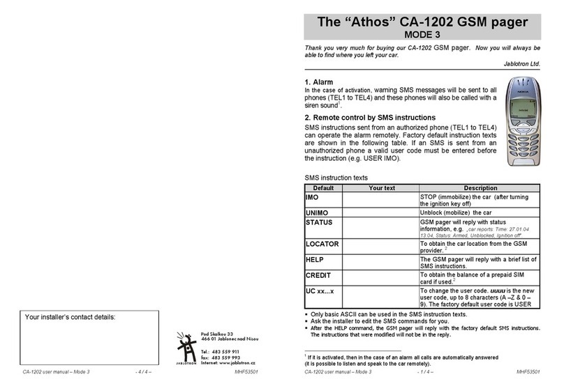
Ver. 1.2, Jul’07
DIY automotive Alarm SYSTEM
1014C

Thank you for purchasing this VISION
1014C Vehicle Security System. The
1014C is a state of the art device that
will provide you with years of trouble
free service if used properly. Please fa-
miliarize yourself with the content of this
Instruction Manual to get the most out
of your new system. We trust you will en-
joy using the product.

© 2005-2007 KIRAMEK, INC.
NOTICE! Although reasonable efforts have been taken to ensure accuracy in this
Instruction Manual, Kiramek Inc. shall not be held liable for any errors, omissions,
property damage, or injury resulting from the use of this information.
All product specifications and features are subject to change without notice.
TABLE OF CONTENTS
One Year Warranty ........................................ 1
Installation ............................................... 2
Precautions & Safety.................................... 3
Installation Tips......................................... 4
Included Items ......................................... 5
Technical Specifications................................. 6
System Wiring Diagram .................................. 7
Main Harness (H1) ...................................... 8
Optional Connections (H2) .............................. 9
Mounting System Components .......................... 12
Adjusting the Shock Sensor ............................. 14
Operation ............................................... 16
Transmitter Functions................................... 17
Transmitter Usage & Care............................... 18
Arming............................................... 19
Disarming ............................................ 20
Panic Mode .......................................... 21
System “Armed” Features............................... 22
Feature Programming .................................. 25
Force Reset........................................... 29
Transmitter Learning ................................... 31
Troubleshooting .......................................... 32

1
© 2005-2007 KIRAMEK, INC.
The VISION 1014C system alarm unit is backed by a one (1) year war-
ranty against defective components and/or improper product assembly
to the original purchaser for as long the vehicle is owned by that same
purchaser. The warranty becomes void if the VISION 1014C system is
moved to another vehicle. All other parts and/or accessories that con-
nect to VISION 1014C systems, including the shock sensor and ultra-
sonic sensor and status LED, are also warranted for one (1) year from
the original date of purchase.
During the warranty period, Kiramek Inc. will repair or replace, at its
sole discretion, any system component that is found defective in mate-
rial or assembly during the warranty period, provided that the product
is returned to Kiramek Inc. or an authorized VISION dealer with a clear
and legible copy of the original purchaser’s receipt. Any damage to your
VISION 1014C system that results from normal wear-and-tear, acci-
dents, improper use, neglect, exposure to high humidity or extreme tem-
peratures, faulty wiring, incorrect installation, modication, removal or
defacement of the product serial number, alteration or repair outside
Kiramek Inc or its Authorized VISION Dealers immediately voids this
warranty.
This warranty is limited to defective parts only and does not provide
any compensation whatsoever for damages associated with the VISION
1014C system or its accessories. This warranty does not cover instal-
lation labor, product removal and/or reinstallation fees. This warranty
is valid for the original purchaser only and may not be transferred to
another party. Kiramek Inc makes no warranty against theft or vandal-
ism of the vehicle in which the VISION 1014C system was installed.
This warranty shall not be interpreted as an insurance policy against
loss, nor shall Kiramek Inc be liable any in way for such loss, nancial
or otherwise.
IMPORTANT! THIS SYSTEM WAS DESIGNED TO BE AN EASY-TO-INSTALL, “DO
IT YOURSELF” PRODUCT, BUT YOU MAY WISH TO CONSIDER PROFESSIONAL IN-
STALLATION IF YOU ARE APREHENSIVE ABOUT AND/OR INEXPERIENCED WITH
WORKING WITH VEHICLE ELECTRONICS. THIS WARRANTY DOES NOT COVER
DAMAGE TO THE VISION PRODUCT OR YOUR VEHICLE CAUSED BY INSTALLA-
TION MISTAKES! BY INSTALLING THIS SYSTEM YOURSELF, YOU ASSUME FULL
RESPONSIBILITY FOR YOUR OWN INSTALLATION AND ANY PROBLEMS THAT
MAY RESULT. CONSIDER THE RISKS BEFORE INSTALLING YOURSELF.
ONE YEAR Warranty

IN S TAL L AT ION

VISION 1014C INSTRUCTION MANUAL
3
Precautions & Safety
OPERATION.
Use of the 1014C outside its intended purpose as described in
this Instruction Manual could result in damage to the vehicle or surround-
ing property, or cause serious injury or even death. Seek professional instal-
lation by an authorized VISION dealer if you feel uncomfortable proceeding
yourself.
SAFETY POINTS TO ABIDE BY
:
Never start the vehicle’s engine in enclosed spaces that lack adequate1.
ventilation. Extended exposure to carbon monoxide exhaust fumes
can result in death!
Do not disconnect the vehicle’s battery, as it could cause serious prob-2.
lems with airbag systems, anti-theft radios or vehicle diagnostics. If
you absolutely must disconnect the vehicle’s battery, rst disconnect
the main power wiring harness of the 1014C and then disconnect the
vehicle’s battery.
Do not proceed with installing this system in vehicles that do not have3.
a 12-volt electrical system. This system will not function in 24-volt
trucks, and any damage resulting from such installation shall be the
sole responsibility of the installer.
Do not install the 1014C alarm unit or associated sensors in or4.
near water, or in a location where water could gather. The 1014
alarm unit is weatherproof but not waterproof, and an electrical short
could occur if water gets inside or shorts a contact in the wire har-
ness. Only an optional siren and the 1014C alarm unit can safely be
installed in the engine compartment, not sensors! (Also see page 33.)
Do not install the 1014C alarm unit in an environment of intense con-5.
densing humidity or steam, in an area with an unusally large number
of airborne particles, or any place where oil could build up inside the
control module case. All of these extreme environments could lead to
an electrical short and possible cause a re.
Avoid installing the 1014C and its associated sensors near sources6.
of intense RF transmissions which could possible interfere with the
operation of the system. If you nd the system is randomly working
and not working, consider relocating the alarm unit and/or sensors.

4
Installation Tips
Steps Toward a Professional Installation:
•Secure all electrical contacts so you cannot easily break the connection
by tugging on the wires. Use solder if required, and securely cover all
connections with electrical tape, heat shrink tubing and/or corrugated
tubing.
•Use only a DMM (digital multi-meter) to test leads or take voltage read-
ings. Do not use “test lights” or “logic probes” (“computer-safe test
lights” included) because they draw a large amount of electrical current
that could overload and destroy sensitive circuitry in the vehicle.
•Manually turn off all lights (such as the dome light) that trigger when
a hatch is opened so you will not run down the battery. If you cannot
manually turn off all the lights, then remove the appropriate fuses and
don’t forget to replace the fuses after your installation is complete.
•Remember to not lock the keys in the car during your installation!
Leave a door open or roll down a window, just in case.
•Consult the vehicle owner about where the Status LED, Alarm Unit,
and Sensors should be mounted.
•If you cannot nd a suitable constant +12 volt power source under the
dash, run a thick-gauge wire direct to the battery terminal. Do not dis-
connect the battery, but rather connect to the battery terminal clamps
by removing the appropriate bolts.
•When running extension wires (such as a +12v lead to the battery),
use a wire gauge that is at least as big or bigger than the wire you are
extending.
Recommended Tools and Accessories:
•DMM (digital multi-meter)
•Battery-powered drill & driver
•Electrical Tape or Heat Shrink Tubing
•Soldering Iron & Solder
•Corrugate Tubing
•Wire Stripper/Crimper
INSTALLATION

5
INCLUDED ITEMS
Alarm Unit (1pc)
2-Button Remote (1pc)
Shock Sensor (1pc)
This Manual (1pc)
Ultrasonic Sensor (1pc)
Status LED (1pc) Main Harness (1pc)
Window Decals (2pc) 2-Sided Tape (2pcs)
Mounting Screws (2pc)
Electrotap (1pc)
Ring & Bullet Connectors
INSTALLATION
1014V

6
VISION 1014C INSTRUCTION MANUAL
Technical Specifications
Operating Voltage:
Current Consumption:
Operating Temp.:
Built-in Siren:
Housing:
Alarm Unit
12Vdc
5mA (armed w/ LED ashing, excludes shock sensor)
-40°C to +110°C
115dB, 1-Tone Piezo
Water-resistant (cannot be submerged)
Shock Sensor
Operating Voltage:
Current Consumption:
Operating Temp.:
Sensor Technology:
Trigger:
12Vdc (fed from Alarm Unit)
5.0mA (avg.)
-40°C to +85°C
Infra-red Beam Deection
2-Stage
Transmitter
Battery Power:
Battery Life:
Normal In-City Range:
RF Transmission:
Housing:
Two CR1616 Lithium Button Cells
1 Year (10 presses per day)
20~30m (65~100ft.)
Digital, 66-bit Rolling Code Security
Waterproof to 1.8m (6ft.)
(Certied for IP40, but also passed IP50 tests)
Ultrasonic Sensor
Operating Voltage:
Current Consumption:
Operating Temp.:
Sensor Technology:
Trigger:
12Vdc (fed from Alarm Unit)
6.0mA (avg.)
-20°C to +75°C
Ultrasonic Audio Transducer
1-Stage

VISION 1014C INSTRUCTION MANUAL
7
SYSTEM WIRING DIAGRAM
15A
Fuse
BLK
RED (+)12v System POWER
GRN/WHT (+)Ignition Input
GRN (
-
)Light Flash Output
WHT (
-
)Door Switch Input
ORG (
-
)Siren Output
(
-
)System GROUND
H1
H2
YEL (
-
)GWA / ST Kill Output
Shock Sensor
(included)
Ultrasonic Sensor
(optional)
Status
LED
Main Harness
Optional
Connections
2-pin
3-pin
4-pin
4-pin
NOTE:As of July 2007, all 1014
systems ship without the H1
Main Harness connectors.
Instead, wires at this point are
factory soldered.
YD-FUSE
IMPORTANT! You must
connect the GRN/WHT (+)
Ignition Input in order to
program features, manually
disarm, or learn transmitters.

8
MAIN HARNESS
This wire is the main (–) ground input to the 1014. Be sure to connect this
wire securely to a good ground source. Most security system installation
problems result from a bad ground connection!
Find a piece of bare metal on the vehicle and use some steel wool to clean it
off before you make your connection. Determine the length of wire needed,
and cut the black wire shorter if necessary. Crimp on the included ring
connector. Screw down your connection tightly.
H1
H1-BLK (–) System GROUND
This wire is the main (+) 12v power input to the 1014. Be sure to connect
this wire securely to a constant 12v source, but connect this wire last so the
siren doesn’t go off.
If you cannot nd a constant 12-volt source under the dash, you may need
to run a wire directly to the positive battery terminal in the engine compar-
ment. If you need to extend this 12v power wire, use wire thicker than the
RED wire. Do not bypass the fuse on the RED wire. If you blow the fuse,
replace with a 15A blade type.
H1-RED (+) System POWER
This cream-colored 4-pin connector is to be attached to the included 318-
052 shock sensor, as shown in the diagram on page 7. Optional sensors
(such as VISION RSA-series eld sensors or the 318-022 digital tilt sensor)
can be easily added to this line with the purchase of an optional 318-035
Sensor Splitter.
H1-4 pin Shock Sensor Connector
This white 3-pin connector can be attached to the included 318-04 ultrason-
ic sensor, as shown in the diagram on page 7. Be sure to keep the control
unit of the Ultrasonic sensor more than 30cm (1ft) away from the body of
the 318-052 shock sensor to avoid interference and possible false alarms.
H1-3 pin Ultrasonic Sensor Connector
INSTALLATION

9
OPTIONAL CONNECTIONS
This wire must be connected to the (+) 12v Igni-
tion line (showing 12v when IG switch is turned
on). You must connect this GRN/WHT wire to
trigger the siren when the ignition goes on (while
Armed), for remote start compatibility (pg.23),
for Force Reset (pg.29), for Feature Programming
(pg.25), and for Transmitter Learning (pg.31).
H2-GRN/WHT (+) Ignition Input
H
2
'2.7(4
34
/.
!##
/&&
)'.)4)/.
37)4#(
H2-GRN (–) Light Flash Output
This wire supplies a (–) 0v Ground (250mA max.) output for ashing the
vehicle’s lights during security breaches (at times of Warning Chirps and
Full Siren Blast). See Fig-1 below. The “Vehicle Light” shown can be the
parking lights, small lights, hazard lights or headlights. It doesn’t matter
which lights you connect to, but you may need an optional relay in some
cases, such as connecting to the hazard (turn signal) lights.
NOTE:
The relay shown in Fig-1 is not an “optional” relay. The
diagram shows the vehicle’s factory relay attached to the factory light
switch. The 1014’s GREEN wire has sufcient output to drive a factory
relay only. Never connect the GREEN wire directly to the vehicle lights!
If you need to invert the polarity from (–) to (+), you will need to purchase
an optional VISION 896H-1C relay.
6%()#,%
,)'(4
6%()#,%å,)'(4
37)4#(
V
6%()#,%å,)'(4
#/.42/,å2%,!9
FIG-1: Connecting Light Flash
'2.
INSTALLATION
Important Connection!

10
VISION 1014C INSTRUCTION MANUAL
H2-WHT (–) Door Switch Input
OPTIONAL CONNECTIONS
H
2
This input detects if a door is opened and is also used for Force Reset — see
page 29. If a door opens while Armed, the siren will go off for 30 seconds or
until Disarmed. This input can also be connected to the trunk if optional
diodes are used. The connection is made between the door (and/or trunk)
switch and the dome (and/or trunk) light as shown below in Fig-2. The
switches shown are open-ciruit (no ground) when the door/trunk is closed.
NOTE:
If you connect the WHITE wire to the trunk, keep in mind that
the siren will go off when the trunk is opened while armed. Disarm the
system before opening the trunk.
!$$å
$)/$%3
425.+å37
$//2å37
$//2å37
7(4
FIG-2: Connecting Door/Trunk Input
$/-%
,)'(4
425.+
,)'(4
"!44%29
This wire supplies a (–) 0v Ground (1.5A max.) output to operate an op-
tional external siren during a security breach. See Fig-3 below.
H2-ORG (–) Siren Output
3)2%.
FIG-3: Connecting to the Siren
/2' 2%$
",+ "!44%29

VISION 1014C INSTRUCTION MANUAL
11
OPTIONAL CONNECTIONS
H
2
H2-YEL (–) GWA / Starter Kill Output
“GWA” stands for “Ground When Armed.” This wire supplies (–) 0v ground
(500mA max.) while the 1014 is armed. This output can be used for a variety
of purposes, with the two most popular being Starter Kill Immobilization
(optional 896H-1B relay required) and Door Locking (optional 318-16U door
lock module required). When the optional door lock module is connected,
doors will lock when the system is Armed and unlock when Disarmed.
When connecting Starter Kill, the Yellow GWA wire is connected to the Yel-
low wire (“86”) of the optional 896H-1B starter kill relay, as shown in Fig-4
below.
TIP: You may also attach low-current devices, such as scanning LEDs and
other automotive illumination products, to the YELLOW wire. These de-
vices will turn on when the 1014 is armed. A relay will be needed if your
combined devices (including starter kill relay) exceed 500mA. See Fig-5
below for example wiring of an optional LED scanner.
OPTIONAL
("
2%,!9
6
)'.)4)/.
37)4#(
A
STARTER
/&&
!##
/. 34
052
CUT
",5
9%,9%,
FIG-4: Starter Kill Wiring
FIG-5: Connection an Optional Scanner
BLACK
YELLOW
RED

12
MOUNTING SYSTEM COMPONENTS
The Alarm Unit is “the brain” of your 1014 system. It therefore should be
installed in a secure location, either under the dash or in the engine com-
partment.
Alarm Unit
Please consult the included “318-04 Ultrasonic Sensor WIRING GUIDE” in
conjunction with the wiring diagram shown on page 7 of this manual.
Ultrasonic Sensor
WARNING!
If you install the Alarm Unit in the engine comparment,
NEVER mount near any source of heat or where water could collect! And
NEVER mount the Alarm Unit near moving parts or in a location where
it can vibrate or move around excessively. The rewall is usually the best
mounting location in the engine compartment. (Also see page 33.)
If you purchased an optional external siren, it may be best to install the
1014 Alarm Unit inside the vehicle and the external siren in the engine
compartment. This way, the built-in piezo siren can then act as a “pain
generator” to further scare off thieves who try to get inside your car.
Locations above or behind the glove box, behind the radio or high up under
the dash are all good mounting places. If you extend wires, always use the
same or larger gauge wire! Solder all large gauge wire connections and cov-
er with electrical tape or heat shrink tubing and/or corrugate tube. Mount
the Alarm Unit to a secure, at surface with the included 2-sided tape or
use wire ties to attached the Alarm Unit to a sturdy factory wire harness.
IMPORTANT!
When considering an appropriate mounting location
under the dash, keep in mind that most thieves hot-wire vehicles by re-
moving the plastic panel just under the steering column.
INSTALLATION
IMPORTANT!
Mount the included 318-052 shock sensor >30cm (1ft.)
away from the main body of the included 318-04 Ultrasonic Sensor. Fail-
ure to do so may cause the shock sensor to randomly false trigger.

13
MOUNTING SYSTEM COMPONENTS
The Status LED is used as a visual theft deterrent when the system is
armed. It also is used to alert you if the siren went off while you were away
from the vehicle.
You can mount the Status LED in any location you like, but keep in mind
that the wire harness is only 150cm (5ft.) long. A recommended mounting
location would be near the door window on the driver’s side where it can be
easily seen (e.g., placed on a switch blank). Use the afxed 2-sided tape to
mount and run the wires out of view.
Status LED
The shock sensor is not waterproof so only mount it inside the vehicle, pref-
erably in a concealed location under the dash. Use the afxed double-sided
tape or screws and mount the shock sensor to the outside of an air duct, to
the inside of a trim panel, or use wire ties to secure it to large wiring har-
ness under the dash. Avoid mounting the shock sensor to the metal body
of the car or on the steering column because sensitivity may become poor.
Test the sensor in your preferred mounting location prior to afxing it with
the included 2-sided tape.
Shock Sensor
IMPORTANT!
Always mount the included 318-052 shock sensor more
than 30cm (1ft.) away from the main body of the included 318-04 Ultra-
sonic Sensor. Failure to do so may cause the shock sensor to randomly
false trigger the siren.
INSTALLATION

14
VISION 1014C INSTRUCTION MANUAL
ADJUSTING THE SHOCK SENSOR
The shock sensor is factory preset to work
well with most vehicles out-of-the-box. How-
ever, if you nd that the siren is going off too
easily, or if the siren doesn’t go off when you
think it should, it’s time to adjust the sensi-
tivity.
Turn the orange sensitivity adjustment knob clockwise to increase sensitiv-
ity and counter-clockwise to decrease. If you cannot nd a suitable adjust-
ment level, consider remounting the shock sensor.
Sensitivity
&ULLå4RIGGER
2%$å,%$
/2!.'%
!DJUSTMENTå+NOB
7ARNING
4RIGGER
'2%%.å,%$
The VISION 318-052 “Active-IR” shock sensor has been engineered to avoid
false triggers in most situations. However, there is still the possibility the
sensor could trigger the siren during a strong earthquake, jackhammer
operation adjacent to the vehicle, hurricane/typhoon, large explosions/re-
works, large animals ramming against the vehicle, etc. If any of these
extreme cases are anticipated, you can avoid false siren triggers simply
by arming the system with the Sensor Bypass Method, which ignores the
shock sensor (see page 19).
Another consideration is temperature. The sensitivity can vary by as much
as 20% under extreme temperature conditions. You may wish to reduce the
sensitivity in hot weather and increase sensitivity in cold weather.
False Alarms
If the shock sensor is not working well or at all, it may be that the suspend-
ed element inside the case was jolted out of position. Disconnect the wire
harness, snap open the shock sensor case, and adjust as shown below.
Suspended Reflector Malfunction
Correct
Alignment Incorrect
Alignment


O P E R AT ION

VISION 1014C INSTRUCTION MANUAL
17
TRANSMITTER FUNCTIONS
OVERVIEW
Button-1
Button-2
LED
BUTTON FUNCTIONS
Button-1• : “Normal Mode” Arm/Disarm (siren sound enabled)
Button-2• : “Silent Mode” Arm/Disarm (siren sound disabled)
Buttons 1 & 2 (short press)• : “Sensor Bypass” Arm
Button 1 or 2 (long press)• : Panic Mode
Keychain Hole
Table of contents
Other Kiramek Car Alarm manuals