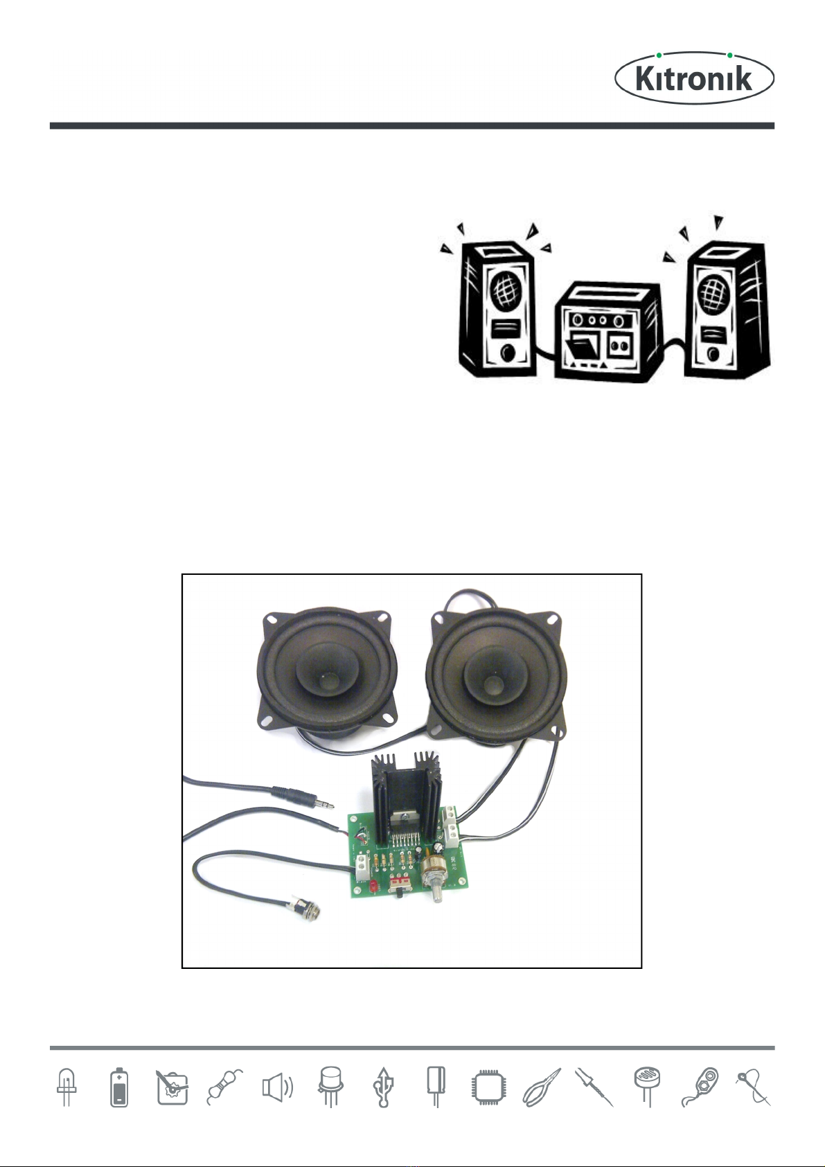
High Power Amp Teaching Resources
www.kitronik.co.uk/2143
Schemes of Work
Two schemes of work are included in this pack; the first is a complete project including the design & manufacture of
an enclosure for the kit (below). The second is a much shorter focused practical task covering just the assembly of
the kit (next page). Equally, feel free to use the material as you see fit to develop your own schemes.
Before starting we would advise that you to build a kit yourself. This will allow you to become familiar with the
project and will provide a unit to demonstrate.
Complete product design project including electronics and enclosure
Introduce the task using The Design Brief sheet. Demonstrate a
built unit. Take students through the
design process using The Design Process sheet.
Homework: Collect examples of amplifiers and accessories. List the common features of these products
on the Investigation / Research sheet.
specification for the project using the Developing a Specification sheet.
Resource: Sample of amplifiers products.
Homework: Using the internet or other search method, find out what is meant by design for
manufacture. List five reasons why design for manufacture should be considered on any design project.
Read Designing the Enclosure sheet. Develop a product design using the Design sheet.
Homework: Complete design.
get the students to model their enclosure design. Al
low them to make alterations to
their design if the model shows any areas that need changing.
Split the students into groups and get them to perform a group design review using the Design Review
sheet.
Using the Soldering in T
demonstrate and get students to practice
Resistor Value and Capacitor Basics worksheets.
Homework: Complete any of the remaining resistor / capacitor tasks.
Build the electronic kit using the Build Instructions.
Complete the build of the electronic kit. Check the completed PCB and fault find i
Checking Your Amplifier PCB section and the fault finding flow chart.
Homework: Read How the Amplifier Works sheet.
Homework: Collect some examples of instruction manuals.
Homework: Read Instruction Manual sheet and start developing instructions for the amplifier.
Using the Evaluation and
Improvement sheet, get the students to evaluate their final product and
state where improvements can be made.
AdditionalWork
Package design for those who complete ahead of others.