Klafs SANARIUM M User manual

Assembly instructions
Klafs SANARIUM M, B, S, C with
Control System Type 18033 3.................................................
Instructions de montage
Klafs SANARIUM M, B, S, C avec
commande type 18033 23......................................................
Instrucciones de montaje
Klafs SANARIUM M, B, S, C con
unidad de control del tipo 18033 43...........................................


Assembly instructions
Klafs SANARIUM M, B, S, C with
Control System Type 18033

Contents Page
1. Intended Use ................................................. 5
2. General safety information ................................... 5
3. Technical data ................................................ 5
4. Control system ............................................... 6
4.1. Operating/display elements ............................................. 6
5. SANARIUM control system scope of supply .................. 7
6. Installing the control system .................................. 8
6.1. Installing the control system housing ....................................... 8
6.2. Inserting the expander circuit board in the control system ...................... 11
7. Mounting the evaporator ..................................... 12
7.1. Mounting and connecting the EL2 evaporator ............................... 12
8. Installing the sensors ......................................... 13
8.1. Installing the humidity sensor FRL 5 ........................................ 13
8.2. Installing the temperature sensors ......................................... 14
9. Mounting optional accessories ............................... 15
9.1. Mounting the interior display with SaunaPUR button (option) .................... 15
9.2. Remote Power On unit (option) ........................................... 16
9.3. Mounting the Climate Manager .......................................... 17
10. System settings ............................................... 18
10.1. Service Menu (01) - CODE, Code number ................................. 18
10.2. Service menu 03 - PUR, SaunaPUR ........................................ 19
10.3. Service menu 19 - VENT, Exhaust air ...................................... 19
10.4. Service menu 20 - KEY, KEYGUARD ....................................... 19
10.5. Service menu 21 - GREE, Green Sauna .................................... 19
10.6. Service menu 22 - TIMR, Preselect mode ................................... 20
10.7. Service menu 23 - PUMP, Filling the scent line ............................... 20
10.8. Service menu 25 - LOCK, activate Operation lockout touchscreen .............. 20
10.9. Service menu 26 - END, End service menu ................................. 20
11. Notes ......................................................... 21
12. Addresses .................................................... 22

SANARIUM
PAGE 5
50701218/12.10
1. Intended Use
The control system is intended for use with the sauna heater checked and approved with the German
VDE or TÜV (Technical Inspection Authority), with or without an evaporator.
The control system is to be used only as intended. Intended use also assumes adherence to the
instructions for operation, installation and servicing as prescribed by the manufacturer. The
manufacturer is not responsible for any damage resulting from unintended use or unapproved
changes to the control system. The user alone carries the risk.
The control system may only be operated, maintained and repaired by persons who are familiar with
the control system and aware of the risks involved. Observe the relevant German VDE regulations as
well as other generally recognised safety rules.
2. General safety information
Read and observe the operating and safety instructions before start-up!
dInstall the Sauna/SANARIUM control system outside the sauna cabin only!
dBefore opening the control system housing, disconnect the control system from the mains.
dThe control system may be only connected to the mains supply by a locally authorised
electrician.
dSauna and SANARIUM installations may only be directly connected to the mains voltage
according to VDE regulations. In the connecting feed line use a residual-current breaker
InNv0.03 A with at least 3 mm contact opening.
dInform Klafs Customer Service of problems that a certified electrician cannot repair!
dRemote actuation (Remote Power On): setting, control and/or regulation of a control unit by a
command or place of installation of the control unit performed outside of the range of vision of
the sauna oven. Remote action (Remote Power On) may be used only together with SKS or
sub-bench heater Bonatherm.
dOnly use original Klafs spare parts!
dUnapproved changes to the control system are not allowed.
dInstall the control system, in accordance with the installation instructions!
dElectrical wiring inside the cabin and the cabin walls must have silicone insulation.
dBefore starting the control system, always make sure that no inflammable objects are on or near
the sauna heater. FIRE RISK.
dThe sauna room has to be viewed before the timer is restarted or the device is switched on by a
separate remote actuation system.
dThis equipment is not intended for use by persons (including children) with reduced, physical,
sensory or mental abilities or by persons with a lack of experience or knowledge, unless they
have received instructions in the use of the equipment or are supervised by a person responsible
for their safety. Children must be supervised to ensure that they will not play with the unit.
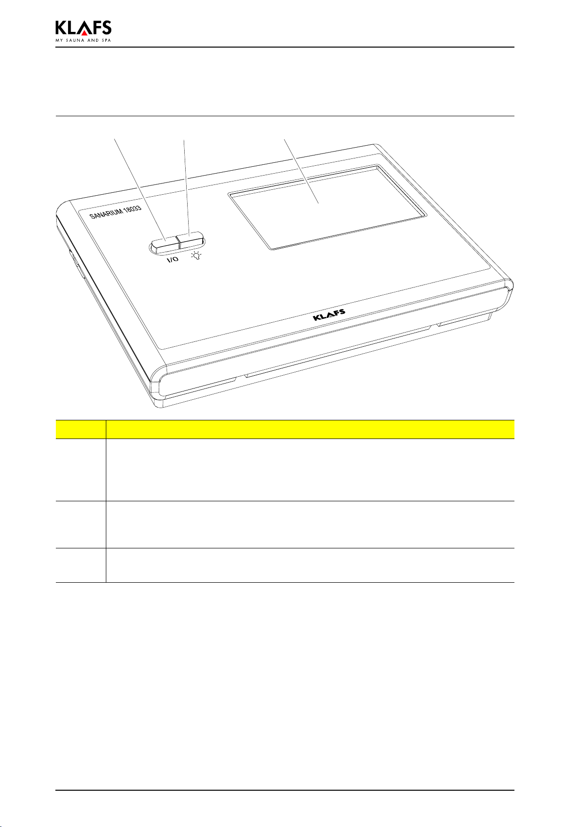
3. Technical data
Control system Type 18033: 3/N/PE ~400 V, max. 9 kW.
Dimensions: W = 325 mm, H = 224 mm, D = 50 mm.
Operating conditions: Temperature 0 °C to 35 °C, max. 80 % relative humidity.

SANARIUM
PAGE 6 50701218/12.10
4. Control system
4.1. Operating/display elements
2 31
Pos. Description
1. Control system main switch.
.The main switch switches off the mains voltage to the control system.
.The internal clock has a power reserve for a few months in the event of a power
outage.
2. Switch cabin light.
.When the control system is connected to the power supply, the cabin light may be
switched On independently of the main switch.
3. Touchscreen.
'See operating instructions.

SANARIUM
PAGE 7
50701218/12.10
5. SANARIUM control system scope of supply
The following components are delivered with the
unit: C
A, B
E
D
A 1 Temperature Sensor - Temp
B 1 Temperature Sensor - Temp/STL
C 1 Bag of Mounting Hardware
D 1 SANARIUM control system
E 1 Humidity sensor FRL 5
- Technical documentation.

SANARIUM
PAGE 8 50701218/12.10
6. Installing the control system
6.1. Installing the control system housing
Open the control system housing
1. With a screwdriver, carefully push and turn
the four lugs one after the other as shown.
2. Once all four interlocks have been released
the front part can be removed.
Continued on the next page

SANARIUM
PAGE 9
50701218/12.10
6. Installing the control system
6.1. Installing the control system housing
Continued
Provide passages for electrical wires
OK FFB = upper edge finished floor.
When mounting the control system housing, leave at least a 50 mm clearance from the wall or other
devices.
Provide openings for the electrical lines on the wall element as shown in the drawing. Run the
electrical wires through the wall element from the rear. Maintain the order shown on the electrical
connection diagram.
2FAN 10 Remote Power On unit
3Outlet 1 11 Interior Display
4Outlet 2 12 Humidity sensor
5Cabin light 13 Temp/STL
6 - 14 SKS
7feed line 15 Temp
8 Evaporator 16 CAN
9Heater supply line 17 KEYGUARD
13 5 7 9 12 14 16
24 6 8
10
11 13 15 17
18
50
50
1510
1506
1493
1484
OK FFB
1470
34
1470
325
220 52
224
196
292 16
Continued on the next page

SANARIUM
PAGE 10 50701218/12.10
6. Installing the control system
6.1. Installing the control system housing
Continued
Install the housing lower section
1. Introduce all electrical wires in their correct
connection sequence from the rear through
the bores into the housing lower section,
together with their respective grommet.
2. Fasten the housing lower section to the wall
element with four countersunk-head screws
(4.4 x 20 mm).
.Do not bend the housing lower section when
fastening. Check mechanical switch function
of main switch.
.To fasten the control system, align the centre
of the unit horizontally with the centre of a
panel.
.Fastening screws must locate on a panel. If
necessary, adjust the housing of the control
system unit to the right or left.
3. Connect the control system according to the
connection diagram.
To ensure correct wiring the wire must be stripped 5 - 6 mm.
Please ensure that no wires stick out.
To insert the wires open the interlock with a screwdriver.
Check the line connection for proper connection.
Connecting optional accessories
To introduce the cables at the appropriate openings in the control system housing,
pierce through the cable grommets.
Connect cable/s to the plug at the
Remote Power On unit, FAI 4 or FAI 5
(option)
1. Strip the wire ends 5 - 6 mm.
2. Open the corresponding interlocks at the plug
with an auxiliary tool and insert the wires
according to the wiring layout.
3. Remove the auxiliary tool and check the line
connection for proper connection.
4. Insert the plug into the socket of the circuit
board.

SANARIUM
PAGE 11
50701218/12.10
6. Installing the control system
6.2. Inserting the expander circuit board in the control
system
The installation of the expansion circuit board is required to operate the control system
by TOUCHCONTROL or IMES-1.
Danger to life!
Contact with current-carrying lines or components is potentially lethal.
De-energise the control system and secure against the unintentional restoration of
power.
Open the housing of the control system
1. Using a screwdriver, carefully turn and insert
lugs (1, 2, 3 and 4) into the housing.
2. Once all four interlocks have been released,
remove the front part.
Place the expander circuit board onto
the pin strip
3. Place expansion circuit board (5) on the pin
strip X8.
.Ensure that the plug base of the expander
circuit board is firmly seated on all pins.
Place the cover back on the housing of
the control system
4. Align the cover and press in until it snaps into
place all around the housing.
5
1
23
4

SANARIUM
PAGE 12 50701218/12.10
7. Mounting the evaporator
7.1. Mounting and connecting the EL2 evaporator
SANARIUM S
1. Open and remove cover of evaporator.
2. Mount the evaporator according to the
installation plan.
3. Connect the evaporator according to the
connection diagram.
4. Put the cover of evaporator back on.

SANARIUM
PAGE 13
50701218/12.10
8. Installing the sensors
8.1. Installing the humidity sensor FRL 5
1. Drill a 10 mm Ø hole for the wiring in the
cabin interior in accordance with the
installation plan.
1370 mm OK FFB
OK FFB - upper edge floor
2. Press a screwdriver into the hollow (1) of the
lock. While simultaneously lifting the housing
cover.
ÑÑÑÑÑÑÑ
ÑÑÑÑÑÑÑ
ÑÑÑÑÑÑÑ
ÑÑÑÑÑÑÑ
ÑÑÑÑÑÑÑ
ÑÑÑÑÑÑÑ
ÑÑÑÑÑÑÑ
1
3. Introduce the electric line for the humidity
sensor with a grommet through the bores into
the housing lower section.
4. Use the screws (3.3 x 20 mm) to fasten the
housing lower section in the centre of the
board through the fastening holes.
5. Connect the humidity sensor according to the
connection diagram.
6. Hook the housing cover into the housing
lower section and press down until it
engages.

SANARIUM
PAGE 14 50701218/12.10
8. Installing the sensors
8.2. Installing the temperature sensors
Temp/STL
dInstall Temp/STL sensor centrally above the
sauna heater.
Temp
dInstall the Temp sensor centrally on the cabin
wall above the bench.
1. Drill Ø 10 mm boring for the line running in
the cabin interior according to the installation
diagram.
2. Run the electric wiring.
Ñ
Ñ
First housing shell
Screws 3.4 x 13 mm
Position the vent slots vertically to
tighten the housing.
3. Screw the first housing shell to the cabin wall.
Screws (3.4 x 13 mm).
Sensor plate
Second housing shell
4. Connect the electric wiring to the sensor plate
according to the connection diagram.
'See installation/connection diagram.
5. Insert the sensor plate into the first half of the
housing.
6. Screw the second housing shell to the housing
shell which has already been mounted.
Screws (3 x 8 mm).

SANARIUM
PAGE 15
50701218/12.10
9. Mounting optional accessories
9.1. Mounting the interior display with SaunaPUR button
(option)
1. Drill a 10 mm Ø hole for the wiring in the
cabin interior in accordance with the
installation plan.
2. Introduce the electric line and provide with a
grommet.
1255 mm OK FFB
OK FFB - upper edge floor
3. Press a screwdriver into the hollow (1) of the
lock. While simultaneously lifting the housing
cover.
ÑÑÑÑÑÑÑ
ÑÑÑÑÑÑÑ
ÑÑÑÑÑÑÑ
ÑÑÑÑÑÑÑ
ÑÑÑÑÑÑÑ
ÑÑÑÑÑÑÑ
ÑÑÑÑÑÑÑ
1
4. Introduce the electric line for the interior
display with a grommet through the bores into
the housing lower section.
5. Use the screws (3.3 x 20 mm) to fasten the
housing lower section in the centre of the
board through the fastening holes.
6. Connect the interior display with the
SaunaPUR button according to the connection
diagram.
7. Hook the housing cover into the housing
lower section and press down until it
engages.

SANARIUM
PAGE 16 50701218/12.10
9. Mounting optional accessories
9.2. Remote Power On unit (option)
Please observe Standard EN 60335 when operating the control system via the Remote
Power On unit.
'Enable the Remote Power On function in Service Menu 20 KEY - see page 19.
Mount the remote Power On unit in dry rooms only and not inside the sauna cabin.
1. Lay the line between the Remote Power On
unit and the control system.
2. Press a screwdriver into the hollow (1) of the
lock. while simultaneously lifting the housing
cover.
ÑÑÑÑÑÑÑ
ÑÑÑÑÑÑÑ
ÑÑÑÑÑÑÑ
ÑÑÑÑÑÑÑ
ÑÑÑÑÑÑÑ
ÑÑÑÑÑÑÑ
ÑÑÑÑÑÑÑ
ÑÑÑÑÑÑÑ
1
3. Introduce the electric line for the Remote
Power On unit with a grommet through the
bores into the housing lower section.
4. Fasten the housing lower section in the
fastening holes with screws (3.3 x 20 mm) or
with dowels.
5. Connect the Remote Power On unit according
to the connection diagram.
6. Hook the housing cover into the housing
lower section and press down until it
engages.

SANARIUM
PAGE 17
50701218/12.10
9. Mounting optional accessories
9.3. Mounting the Climate Manager
1. Drill a 10 mm Ø hole for the wiring in the
cabin interior in accordance with the
installation plan.
2. Introduce the electric line and provide with a
grommet.
1370 mm OK FFB
OK FFB - upper edge floor
3. Press a screwdriver into the hollow (1) of the
lock. While simultaneously lifting the housing
cover.
ÑÑÑÑÑÑÑ
ÑÑÑÑÑÑÑ
ÑÑÑÑÑÑÑ
ÑÑÑÑÑÑÑ
ÑÑÑÑÑÑÑ
ÑÑÑÑÑÑÑ
ÑÑÑÑÑÑÑ
1
4. Introduce the electric line for the Climate
Manager with a grommet through the bores
into the housing lower section.
5. Use the screws (3.3 x 20 mm) to fasten the
housing lower section in the centre of the
board through the fastening holes.
6. Connect the Climate Manager according to
the connection diagram.
7. Hook the housing cover into the housing
lower section and press down until it
engages.

SANARIUM
PAGE 18 50701218/12.10
10. System settings
10.1. Service Menu (01) - CODE, Code number
Prerequisite:
The control system must be switched on and in standby mode. There should be no
programs running.
Call up Service Menu
1. Press the four symbols (1, 2, 3, 4) one after
the other.
57 8
By pressing the correct positions on
the touchscreen the Service Menu
may be called up even if the symbols
are not displayed.
.Enter code number 7452 (5) to call up the
Service Menu.
2. Enter each individual code digit by pressing
the +/-symbols (6) and confirm each one
by pressing the OK symbol (7).
Once the correct four-digit code has been entered,
the Service Menu is displayed, together with the
symbol (8).
6
1
4
2
3
Press one of the symbols (9) to directly select the
corresponding service menu, e.g. 04 (10).
The service menu can also be selected using the
+/-symbols (6).
A selected service menu (10) is displayed by
pressing the OK symbol (7).
Example: service menu 04
dService menu number (10) (selectable)
dService menu name (11) (display)
dStored value (12)
1 Hz = adjustable
2 Hz = display
dStorage cell (13) (display).
1211 109
14 13
Exiting the service menu
By pressing the On/Off symbols (14).
Or select the last Service Menu (26) END and
finish by pressing the OK symbol.
If no operation is active after a period of more than 60 seconds, the control system
automatically exits the service menu and switches to standby mode.
Modifications within a service menu that were not previously closed by pressing OK
will not be recorded.

SANARIUM
PAGE 19
50701218/12.10
10. System settings
Call up Service Menu
'See page 18.
10.2. Service menu 03 - PUR, SaunaPUR
Input:
0= SaunaPUR disabled 1 = SaunaPUR enabled
.Connect SKS to Klafs-IMES-1
with bathing type SaunaPUR
enabled.
2 = SaunaPUR enabled
.If the internal display
FAI 4/FAI 5 is connected, the
SKS can be connected to the
control system.
10.3. Service menu 19 - VENT, Exhaust air
Input:
0= Fan 1 = Electrical sealing flap
10.4. Service menu 20 - KEY, KEYGUARD
Input:
0=KEYGUARD function disabled 1 = KEYGUARD function enabled
2 = Remote activation when Remote
Power On is connected 3 = CBC/ Remote Power On without
KEYGUARD
10.5. Service menu 21 - GREE, Green Sauna
Input:
0=Green Sauna disabled 1 = Green Sauna enabled
2 = Green Sauna with fan after-run

SANARIUM
PAGE 20 50701218/12.10
10. System settings
Call up Service Menu
'See page 18.
10.6. Service menu 22 - TIMR, Preselect mode
Input:
0=Preselect mode Off 1 = Preselect mode On
10.7. Service menu 23 - PUMP, Filling the scent line
Input:
0=No filling of the scent line 1 = Filling the scent line
.The filling process takes approximately 3 minutes.
10.8. Service menu 25 - LOCK, activate Operation lockout
touchscreen
Input:
0=Deactivate Operation lockout
touchscreen 1 = Activate Operation lockout
touchscreen
10.9. Service menu 26 - END, End service menu
By pressing the On/Off symbol.
Or select the last Service Menu (26) via the +/-symbols and finish by pressing the OK symbol.
Other manuals for SANARIUM M
2
This manual suits for next models
4
Table of contents
Languages:
Popular Hot Tub manuals by other brands

Jacuzzi
Jacuzzi Finestra FL61000 Installation & operation instructions

American Standard
American Standard Cadet Elite Corner Whirlpool 2775E parts list

Jacuzzi
Jacuzzi Muse Preinstallation manual

Softub
Softub 140 owner's guide

American Standard
American Standard Cadet Elite 2772E SERIES installation instructions

Wave
Wave ATLANTIC Installation and user manual