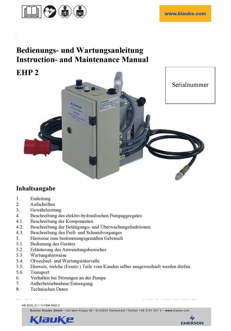
Klauke EHP4230 User manual

Anzahl der Seiten: YY
HE.12929_E © 05/2011 TE-2
Verbindungen mit System
The Power of Partnership
Gustav Klauke GmbH • Auf dem Knapp 46 • D-42855 Remscheid
Telefon ++49 +2191-907-0 • Telefax ++49 +2191-907-141 • www.klauke.textron.com
Serialnummer
EHP4230
D Bedienungsanleitung
GB Instruction Manual
F Mode d´emploi
Hydraulisches Pumpenaggregat
Hydraulic pump unit
HE.12551_B
Gustav Klauke GmbH • Auf dem Knapp 46 • D-42855 Remscheid
EHP4/230
max. Betriebsüberdruck:
max. operating pressure: 700 bar
Nennleistung:
nominal output: 0,75 kW
Förderleistung:
delivery rate: max. 0,82l/min
eingefüllte Ölmenge:
oil volume: 2,1 l
Serien-Nr.:
serial#:
Schutzart:
protection class: IP 54
Baujahr:
year of manufacture: ________
Nennspannung: 230 V /
nominal voltage: 50 - 60 Hz

Bedienungsanleitung
EHP4230
I
HE.12929_E © 05/2011
Bild/pic./fig. 1 (siehe/see Tab. 1)
Pos. Bezeichnung Description Désignation
1 Hauptschalter Main switch Interrupteur principal
2 Steckbuchsen Socket Fiches
3 Anzeige &
Stellknopf
Display &
speed adjustment
Affichage &
bouton de réglage
4 Öleinfüllstutzen Oil filler cap scew Goulot de remplissage d‘huile
5 Schauglas Check glas Regard
6 Netzstecker Mains plug Prise électrique
7 Sicherheits-
fußschalter
Safety foot switch Interrupteur de
sécurité à pédale
8 Hydraulikkupplung Hydraulic coupling Coupleur hydraulique
9 Tragegriff Handle Poignée
10 Entriegelungsknopf Reset button Bouton de déverrouillage
11 Steuerungs-
wahlschalter
Control mode switch Sélecteur de commande
12 Betriebswahlschalter Operating mode switch Sélecteur de mode
1
7
2
6
8
9
10
11
12
Hydraulisches Pumpenaggregat
Hydraulic pump unit
HE.12551_B
Gustav Klauke GmbH • Auf dem Knapp 46 • D-42855 Remscheid
EHP4/230
max. Betriebsüberdruck:
max. operating pressure: 700 bar
Nennleistung:
nominal output: 0,75 kW
Förderleistung:
delivery rate: max. 0,82l/min
eingefüllte Ölmenge:
oil volume: 2,1 l
Serien-Nr.:
serial#:
Schutzart:
protection class: IP 54
Baujahr:
year of manufacture: ________
Nennspannung: 230 V /
nominal voltage: 50 - 60 Hz
54
3
Hydraulisches Pumpenaggregat
Hydraulic pump unit
HE.12551_B
Gustav Klauke GmbH • Auf dem Knapp 46 • D-42855 Remscheid
EHP4/230
max. Betriebsüberdruck:
max. operating pressure: 700 bar
Nennleistung:
nominal output: 0,75 kW
Förderleistung:
delivery rate: max. 0,82l/min
eingefüllte Ölmenge:
oil volume: 2,1 l
Serien-Nr.:
serial#:
Schutzart:
protection class: IP 54
Baujahr:
year of manufacture: 2011
Nennspannung: 230 V /
nominal voltage: 50 - 60 Hz

Bedienungsanleitung
EHP4230
II
Kennzeichnung des Isolierschlauches und -leitung:
z.B. QC36252857 Produktionsseriennummer
Parker Schlauchhersteller
Polyflex 2380N-04V00 Schlauchtyp
DN 6 1/4“ Nennweite
(z.B. 4Q10) Quartal und Jahr der Herstellung
PN 70,0 MPa (10150 psi)
700 bar maximal Betriebsdruck 700 BAR
M-JJJJ Konfektionierdatum z.B. 3-2011
Marking of the insulation hose and fitting:
e.g. QC36252857 produktion serial number
Parker manufacturer of the hose
Polyflex 2380N-04V00 type of hose
DN 6 1/4” nominal width
(e.g. 4Q10) quarter and Year of production
PN 70,0 MPa (10150 psi) max. approved operating pressure
700 bar of the hose 700 BAR
M-YYYY Assembly date e.g. 3-2011
Marquage de la gaine et du tuyau isolants:
par ex. QC36252857 Numéro de série de production
Parker Fabricant de flexibles
Polyflex 2380N-04V00 Type de flexible
DN 6 1/4“ Diamètre nominal
(par ex. 4Q10) Trimestre et année de fabrication
PN 70,0 MPa (10150 psi) 700 barsPression de service
maximale 700 BARS
M-AAAA Date de fabrication par ex. 3-2011
M-YYYY Assembly date e.g. 3-2011
<-- Parker Polyflex 2380N-04V00 DN 6 ( 1/4“) PN 70,0 MPa (10150 psi) 4Q10 QC36252857
M-JJJJ 700 bar
HE.12929_E © 05/2011
Bild/pic./fig. 2

Bedienungsanleitung
EHP4230
1
D
HE.12929_E © 05/2011
Inhaltsangabe
1. Einleitung
2. Gewährleistung
3. Beschreibung des elektro-hydraulischen Pum-
paggregates
3.1 Beschreibung der Komponenten
3.2 Beschreibung der Betätigungs- und Überwa-
chungsfunktionen
3.3.1 Beschreibung des Preß- bzw. Schneidvorganges
3.3.2 Beschreibung von Stanzvorgängen
3.3.3 Beschreibung von Biegevorgängen
4. Hinweise zum bestimmungsgemäßen Ge-
brauch
4.1 Bedienung des Gerätes
4.2 Erläuterung des Anwendungsbereiches
4.3 Wartungshinweise
4.4 Ölwechsel- und Wartungsintervalle
4.5 Hinweis, welche (Ersatz-) Teile vom Kunden
selber ausgewechselt werden dürfen.
4.6 Transport
5. Verhalten bei Störungen an der Pumpe
6. Außerbetriebnahme/Entsorgung
7. Technischen Daten
Kurzinspektion vor Inbetriebnahme
Bitte prüfen Sie, ob Sie alle im Lieferumfang angeführten
Teile erhalten haben.
Lieferumfang:
1 elektro-hydraulische Pumpe Typ EHP4
1 Sicherheitsfußschalter Typ FTA1
1 3m Hochdruckschlauch mit Kupplungsstecker Typ HS23
1 Netzanschlußkabel
1 Schlüssel zum Öffnen des Gehäuses
1 Bedienungsanleitung
Symbole
Sicherheitstechnische Hinweise
Bitte unbedingt beachten, um Personen- und
Umweltschäden zu vermeiden.
Anwendungstechnische Hinweise
Bitte unbedingt beachten, um Schäden am
Werkzeug zu vermeiden.
1. Einleitung
Vor Inbetriebnahme Ihres Schneidwerk-
zeuges lesen Sie sich die Bedienungsan-
leitung sorgfältig durch.
Benutzen Sie dieses Gerät ausschließlich für den bestim-
mungsgemäßen Gebrauch unter Berücksichtigung der all-
gemeinen Sicherheits- und Unfallverhütungsvorschriften.
Pressungen, Stanzungen und Biegevorgänge mithilfe
dieses Gerätes dürfen nur durch eine elektrotechnisch
unterwiesene Person durchgeführt werden. Das Mindest-
alter beträgt 16 Jahre.
Diese Bedienungsanleitung ist während der gesamten
Lebensdauer des Werkzeuges mitzuführen.
Der Betreiber muß
• dem Bediener die Betriebsanleitung zugänglich ma-
chen und
• sich vergewissern, daß der Bediener sie gelesen und
verstanden hat.
2. Gewährleistung
Die Gewährleistung beträgt bei sachgemäßer Bedienung
und unter Einhaltung der geforderten regelmäßigen Kon-
trollen 1 Jahr ab Lieferdatum.
3. Beschreibung der elektro-hydrauli-
schen Pumpe
3.1 Beschreibung der Komponenten
Die elektro-hydraulischen Pumpaggregate mit unserer
Typbezeichnung EHP4 bestehen aus folgenden Kompo-
nenten:
Tabelle 1
Pos. Bezeichnung Beschreibung, Funktion
1 Hauptschalter Ein/Aus für Netzstrom
2Steckbuchsen für Fußbetrieb, Zweihandsteuerung
und Näherungsschalter
3Anzeige &
Stellknopf
ermöglicht das Einstellen des
Fördervolumens bzw.
der Lochergröße
4Öleinfüllstut-
zen
Einfüllstutzen für das Hydrauliköl
5Schauglas Zeigt den Ölfüllstand an
6Netzstecker für Wechselstrom (Schuko)
7Sicherheitsfuß-
schalter
GS-geprüfter 3-Stufen Sicher-
heitsfußschalter zur Steuerung
des Aggregates
8Hydraulik-
kupplung
Kupplungsmuffe zum Anschluß
eines stahlarmierten Hochdruck-
hydraulikschlauch mit CEJN
Kupplungsstecker an beiden Seiten
9Tragegriff Vorrichtung zum Transport
der Pumpe
10 Entriegelungs-
knopf
Dient zur Wiederinbetriebnahme
des Fußschalters nach Inanspruch-
nahme der 3‘ten Stufe
11 Steuerungs-
wahlschalter
Zum Einstellen der Frequenz und
Zuschalten der Steuerung
12 Betriebswahl-
schalter
Zuschalten z.B. des Rücklaufstopps
für den Betrieb des Stromschienen-
biegegerätes oder des Stanzbetriebs
für den konfortablen Betrieb der
Greenlee Stanzköpfe.
3.2 Beschreibung der Betätigungs- und
Überwachungsfunktionen
Nach Einschalten des Hauptschalters (Bild 1.1) und Zu-
schalten des Steuerungswahlschalters (Bild 1.11) auf
Pos 1 wird der Betriebswahlschalter (Bild 1.12) auf die
jeweilig Anwendung eingestellt. Anschließend wird der
Arbeitsvorgang durch die Betätigung des Sicherheitsfuß-
schalter (Bild 1.7) ausgelöst. Der Vorgang läuft i.d.R.
automatisch ab und schaltet nach Erreichen des max.
Betriebsüberdrucks selbständig ab. Das Gerät ist mit ei-
nem Nachlaufstopp ausgerüstet, der den Vorschub nach
Loslassen oder Durchtreten des Sicherheitsfußschalters
sofort stoppt.

Bedienungsanleitung
EHP4230
2
D
HE.12929_E © 05/2011
Zum Einrichten der Pumpe wird das Gehäuse unter Ver-
wendung des im Lieferumfang befindlichen Schlüssels
geöffnet. Die Einstellung z.B. der Kolbenvorschubge-
schwindigkeit oder auf die jeweiligen Lochstanzeinsätze
erfolgt durch Drehen des Steuerungswahlschalters auf
die Position ‚Einrichten’ bei gleichzeitiger Justierung der
Stellknopfes (Bild 1.3) auf den in der Tabelle vorgeschrie-
benen Wert.
Desweiteren verfügt die Pumpe über einen Betriebswahl-
schalter (Bild 1.12) für die Auswahl des Betriebszustan-
des, z.B. Normalbetrieb, Rücklaufstopp und Stanzbe-
trieb.
Betriebszustand Beschreibung
Normalbetrieb Kolben läuft nach Loslassen des
Sicherheitsfußtasters in die Aus-
gangsstellung zurück.
Rücklaufstopp Kolben verharrt nach Loslassen des
Sicherheitsfußschalters in der er-
reichten Position. Nach nochmaliger
Betätigung wird der Arbeitsvorgang
fortgesetzt.
Stanzbetrieb Der Stanzvorgang besteht aus
einem Schnellvorschub und einem
Schleichgang.
Der Druckaufbau kann jederzeit an einem an der Pumpe
auf Wunsch angebrachten Manometer verfolgt werden.
3.3.1Beschreibung des Preß- bzw. Schneidvor-
ganges
Beim Preßvorgang werden die Werkzeugeinsätze gegen-
einander gefahren. Der auf das Kabel aufgeschobene
Kabelschuh/Verbinder befindet sich bei geschlossenem
Preßkopf in der feststehenden Hälfte des Preßeinsatzes.
Der auf der Kolbenstange sitzende bewegliche Teil des
Preßeinsatzes bewegt sich dabei auf die Preßstelle zu.
Eine Pressung ist abgeschlossen, wenn die Werkzeugein-
sätze vollständig zusammengefahren sind.
Weitere Hinweise zur Verpressung von Verbindungsma-
terialien entnehmen Sie bitte unserem Montagehinweis
im Katalog.
Bei Schneidvorgängen nach dem Scherenprinzip wird
das Kabel in die geöffneten Schneidbacken des Schneid-
kopfes eingelegt, bzw. der Schneidkopf so an das Kabel
angelegt, sodaß sich die Lage des Schneidkopfes wäh-
rend der gesamten Schneiddauer nicht ändert.
Um ungünstige Scherwirkungen zu vermeiden müssen
die Scheren immer lotrecht auf das zu schneidende Ka-
bel zufahren.
Bei dem Scherenprinzip bewegen sich zwei Messer
gleichzeitig auf das zu schneidende Kabel zu.
3.3.2Beschreibung von Stanzvörgängen
Ein Stanzvorgang wird gekennzeichnet durch das Einzie-
hen des Stempels in die Matrize. Dazu muß der Stempel
bis an das Blech herangeschraubt werden.
Der Stanzbetrieb ist gekennzeichnet durch 2 Geschwin-
digkeiten, einen schnellen Stanzbetrieb und einen lang-
samen Schleichgang. Nach Beendigung des Stanzvor-
ganges schaltet die Pumpe in einen sehr langsamen
Schleichgang um eine Zerstörung von Stempel und Ma-
trize durch ungewollte Kontaktierung von Stempel und
Matrizenboden zu verhindern. Hierbei handelt es sich um
eine Komforteinstellung.
3.3.3Beschreibung von Biegevörgängen
Der Betriebszustand mit Rücklaufstopp eignet sich be-
sonders für den Betrieb des Stromschienenbiegegerätes
in Verbindung mit dem Näherungsschalter.
Im Rücklaufstoppbetrieb kann der Arbeitshub in jeder Po-
sition unterbrochen werden ohne dass der Kolben in die
Ausgangslage zurückfährt. Bei nochmaliger Betätigung,
z.B. des Handtasters des Stromschienenbearbeitungs-
zentrums, wird der Arbeitszyklus an dieser Stelle fortge-
setzt. Durch eine sehr kurze Betätigung des Handtasters
kann der Kolben im Fehlerfall in die Ausgangsstellung
zurückgefahren werden.
Für weitere Hinweise lesen Sie bitte die Bedienungsanlei-
tung des Stromschienenbiegegerätes.
4. Hinweise zum bestimmungsgemä-
ßen Gebrauch
Es muß darauf geachtet werden, daß das Pumpaggregat
standsicher auf einer ebenen Fläche mit einem maxima-
len Neigungswinkel von 15° aufgestellt wird.
4.1 Bedienung des Gerätes
1.Der Kupplungsstecker des Hydraulikschlauches wird
mit der an der Pumpe befindlichen Kupplungsmuffe
verbunden.
2.Auswahl des zu verwendenden Preß-/Schneid-/Stanz-
kopfes nebst Lochwerkzeugen oder des Stromschie-
nen-biegegerätes nebst Zubehör.
3.Die ausgewählte Arbeitseinheit wird mit der Pumpe ver-
bundenen. Bei Greenlee Werkzeugen ist der Adapter
CMGSK zu verwenden.
Achtung
Pumpe nicht ohne Arbeitseinheit betreiben!
Achtung
Vor Inbetriebnahme Ölstand prüfen und ggf.
auffüllen.
4.Der Sicherheitsfußschalter (FTA1) bzw. die Zweihand-
sicherungssteuerung (ZST3) oder der Näherungsschal-
ter des Stromschienenbearbeitungszentrums wird über
die Steckvorrichtung (Bild 1.2) mit der Pumpe verbun-
den.
5.DerHauptschalterfürdenNetzstrom(Bild1.1)wirdeinge-
schaltet und der Stanzkopf wird in Position gebracht.
6.Zum Einrichten der Pumpe wird die Tür mithilfe eines
speziellen Schlüssels geöffnet. Der Steuerungswahl-
schalter (Bild 1.11) wird auf „Einrichten“ gestellt und
gleichzeitig über der Stellknopf (Bild 1.3) auf den ge-
forderten Wert (s. Anzeige) eingestellt. Den Wert für die
jeweilige Anwendung entnehmen Sie bitte einer auf der
Türinnenseite aufgeklebten Tabelle.
Achtung
Das Einrichten der Pumpe auf die jeweiligen An-
wendungsbereiche wird ausschließlich durch
geschulte Vorarbeiter vorgenommen.
Die Tür ist anschließend wieder sicher zu verschließen.

Bedienungsanleitung
EHP4230
3
D
HE.12929_E © 05/2011
7.Wählen Sie den gewünschten Betriebszustand mit Hil-
fe des Betriebswahlschalters (Bild 1.12). Es bieten sich
Kombinationen an:
Anwendung
Betriebszustand Rücklauf-
stopp Normal-
betrieb Stanz-
betrieb
Stanzen
(z.B. LSK120, 1731&2) XX
Lochen
(z.B. 746) X
Biegen
(z.B. SBZ, 882, 880, 747) X
Schneiden
(z.B. SDK_, SDG_) X
Pressen (z.B. PK60UNV,
PK12042, PK06FT,
PK22, THK120 etc.) XX
SBZ=Stromschienenbiegezentrum
8.1 Stanzen
Nachdem der Stellknopf (Bild 1.3) auf den in der Tabelle
vorgeschriebenen Wert eingestellt wurde, wird der Stanz-
vorgang durch Betätigung des Sicherheitfußschalters
eingeleitet. Der Rücklaufstopp ermöglicht eine genauere
Positionierung im Vergleich um Normalbetrieb.
8.2 Lochen
Wie in den vorrangegangenen Schritten beschrieben,
wird die verwendete Lochergröße über den Stellknopf
(Bild 1.3) eingestellt (s. Tabelle). Der Stempel muß un-
mittelbar an das zu stanzende Blech herabgeschraubt
werden. Die Auslösung des Lochvorganges erfolgt über
den Sicherheitsfußschalter. Kurz vor oder kurz nach dem
vollständigen Durchstanzen des Bleches schaltet die
Pumpe in den Schleichgang. Dadurch erhält der Bediener
deutlich mehr Zeit um den Stanzvorgang sicher und ohne
Beschädigung der Stanzeinsätze zu beenden.
8.3 Biegen
Wird die Pumpe mit dem Stromschienenbiegezentrum
(SBZ) betrieben, so muß der Näherungsschalter über die
Steckbuchse (Bild 1.2) mit der Pumpe verbunden wer-
den. Der Bediener kann nun entscheiden, mit welcher
Geschwindigkeit er den Biegevorgang ablaufen lassen
möchte. Dieses kann wie schon beschrieben über den
Stellknopf (Bild 1.3) eingestellt werden. Durch den Rück-
laufstopp kann sich der Bediener an den optimalen Win-
kel herantasten. Durch sehr kurze Betätigung des Tasters
kann der Biegevorgang abgebrochen werden.
8.4 Schneiden
Ein Schneidvorgang erfolgt in der Regel im Normalbe-
trieb, d.h. nach Erreichen des max. Betriebsdrucks öffnen
sich die Messer automatisch.
8.5 Pressen
Bei der Verpressung von Kabelschuhen oder Verbindern
besteht die Option eine Rücklaufunterbrechung (Bild 1.12)
z.B. besseren Positionierung des Verbindungsmaterials
oder zur Sicherstellung einer einwandfreien Verpressung,
einzustellen. Der Sicherheitsfußschalter/ Zweihandsiche-
rungssteuerung wird betätigt. Bei Loslassen des Fuß-
schalters oder der Zweihandsicherungssteuerung bleibt
dann der Kolben in der letzten Position stehen und läuft
nicht zurück.
Achtung
Im Fehlerfall kann der Kolben durch sehr kurze
Betätigung oder Durchtreten z.B. des Sicher-
heitsfußtasters auch bei eingeschaltetem Rück-
laufstopp zurückgefahren werden.
Der Preßvorgang kann durch Betätigung des Sicherheits-
fußschalters aus der letzt erreichten Position fortgesetzt
werden. Der Pressvorgang läuft nun automatisch ab, d.h.
nach Erreichen des fest eingestellten Druckes schaltet
das Gerät selbständig ab. Der Kolben kann bei einge-
schaltetem Rücklaufstopp durch Betätigung des Sicher-
heitsfußschalters während des Rücklaufs gestoppt wer-
den.
Achtung
Der Stanz-, Loch-, Preß- bzw. Schneidvorgang
kann jederzeit durch Loslassen und Durchtreten
des Sicherheitsfußschalters, bzw. Loslassen
der Zweihandsicherungssteuerung unterbro-
chen werden.
Ist der Sicherheitsfußschalter (Bild 1.7) einmal ganz
durchgetreten worden, so muß er durch Drücken des
Entriegelungsknopfes (Bild 1.10) wieder betriebsbereit
gemacht werden.
Achtung
Vor Auswechselung der Werkzeug-/
Schneideinsätze unbedingt den Haupt-
schalter für den Netzstrom gegen unbe-
absichtigtes Betätigen ausschalten.
4.2 Erläuterung des Anwendungsberei-
ches
Unsere elektro-hydraulischen Pumpen vom Typ EHP4
können mit allen in unserem Katalog befindlichen Köpfen
betrieben werden.
Achtung
Es dürfen keine unter Spannung stehen-
den Teile gelocht, verpreßt, bzw. geschnit-
ten werden.
Vor Arbeitsbeginn ist ein spannungsfreier Zustand des Ar-
beitsumfedes sicherzustellen.
Die Geräte sind nicht für den Dauerbetrieb geeignet. Es
muß nach ca. 100 Verpressungen bzw. 80-90 Schnitte
hintereinander eine kurze Pause von mindestens einer
viertel Stunde eingelegt werden, damit dem Gerät Zeit
zur Abkühlung gegeben wird.
Achtung
Bei zu intensivem Gebrauch mit entsprechender
Erhitzung kann es zu Schäden am Gerät kom-
men.
Achtung
Beim Betrieb von Elektromotoren können Fun-
ken entstehen, die feuergefährliche oder explo-
sive Stoffe in Brand setzen können.
Achtung
Das elektrohydraulische Aggregat darf nicht bei
starkem Regen oder unter Wasser eingesetzt
werden.
Das Gerät kann in einem Temperaturbereich von -20°C
bis +40°C sowohl im Innen- als auch im Aussenbereich
eingesetzt werden.

Bedienungsanleitung
EHP4230
4
D
HE.12929_E © 05/2011
Aufgrund einer normativen Überschreitung des Grenz-
wertes für Oberschwingungsströme ist das zuständige
Energieversorgungsunternehmen vor Anschluß an das
öffentliche Netz zu informieren.
4.3 Wartungshinweise
Das elektro-hydraulische Aggregat ist nach jedem Ge-
brauch zu reinigen und ein trockener Zustand vor Einla-
gerung sicherzustellen.
Das Aggregat ist weitgehend wartungsfrei. Lediglich der
Ölstand ist regelmäßig zu kontrollieren und das Aggregat
ist nach möglichen Beschädigungen zu untersuchen.
Die EHP4 besitzt ein Schauglas (Bild 1.5) an dem der
Ölstand jederzeit abgelesen werden kann.
Der Ölstand sollte sich ca. 10 mm unterhalb der Oberkan-
te des Schauglases befinden. Ist der Ölstand zu niederig
muß entsprechend ÖL nachgefüllt werden.
Folgende Hydrauliköle können bei Umgebungstempera-
turen von -20°C bis +40°C verwendet werden:
Hydrauliköle auf Esterbasis: Rivolta S.B.H. 11, Shell Na-
turell HF-E 15
Mineralöle: Shell Tellus T 15, AVIA HVI 15, Mobil DTE 11,
NUTO H 15, Rando HD - Z15, Agip OSO 15, BP Energol
HLP 15.
Es können auch andere vergleichbare Hydrauliköle ver-
wendet werden.
Der Hydraulikschlauch (Bild 1.8) und die Armaturen müs-
sen vor und nach der Anwendung auf Beschädigungen
und Undichtigkeiten hin überprüft werden.
4.4 Ölwechsel- und Wartungsintervalle.
Es ist empfehlenswert, das Gerät in regelmäßigen Ab-
ständen durch einen Sachkundigen zu warten, um einen
einwandfreien Zustand vor dem nächsten Gebrauch zu
gewährleisten.
Tabelle 2 - Wartungsplan:
Was? Wann? Wer?
Reinigen nach jedem
Gebrauch
Bediener
Ölstand prüfen wöchentlich Bediener
Hochdruck-
schlauch prüfen
wöchentlich Sachkundigen
Ordungsgemäßer
Zustand
¼-jährlich Elektrofachkraft
Hydrauliköl
wechseln
jährlich Werk/Sachkundigen
Das Hydrauliköl ist nach spätestens einem Jahr oder bei
häufigem Gebrauch nach ca. 10.000 Verpressungen,
bzw. 8000 Schnittvorgängen, komplett auszutauschen.
Wir empfehlen, diesen Ölwechsel im Werk ausführen zu
lassen.
Achtung
Bitte verwenden Sie nur sauberes, einwandfrei-
es Hydrauliköl
(Rivolta S.B.H 11 und andere Hydrauliköle gleicher Qua-
lität).
Achtung
Hydrauliköle können Hautausschläge und ande-
re Gesundheitsschädigungen hervorrufen. Ver-
meiden Sie längeren Hautkontakt. Waschen Sie
sich nach jedem Kontakt gründlich.
Achtung
Verschüttetes Hydrauliköl muß sofort mit Saug-
material gebunden werden.
4.5 Hinweis welche (Ersatz-) Teile vom
Kunden selber ausgetauscht werden
dürfen.
Innerhalb des Gewährleistungszeitraums darf vom Kun-
den nur das Öl gewechselt werden.
Achtung
Versiegelung der Druckeinstellschraube nicht
beschädigen!
Führen Sie keine eigenen Reparaturen durch und entfer-
nen Sie keine Bauteile wie Schrauben oder andere Kom-
ponenten.
4.6 Transport
Das Hydraulikaggregat sollte, um Beschädigungen beim
Transport zu vermeiden, in einem Transportkoffer trans-
portiert werden. Dabei ist darauf zu achten, daß der Hy-
draulikschlauch ordentlich aufgerollt wird. Der Mindest-
knickradius von max. 70 mm darf nicht unterschritten
werden.
Achtung
Die Pumpe darf nicht horizontal transportiert
oder gelagert werden, da ansonsten Öl austritt.
5. Verhalten bei Störungen an der
Pumpe
Erreicht die Pumpe nicht Ihren vollen Druck, so kann Luft
in das System eingedrungen sein.
Abhilfe: Halten Sie bitte den Preß-, Stanz- oder Schneid-
kopf tiefer als die elektrische Pumpe und betätigen Sie
den Sicherheitsfußschalter bzw. Zweihandsicherungs-
steuerung bis die Preßeinsätze oder Schneidmesser ihre
Endlage erreicht haben. Diesen Vorgang wiederholen Sie
bitte 2-3 mal. Erreicht die Pumpe dann noch nicht den
vollen Druck, so muß der Entlüftungsvorgang wiederholt
werden.
Tritt Hydrauliköl an der Pumpe oder am Preß- bzw.
Schneidkopf aus, muß das jeweilige Bauteil oder ggf. das
gesamte Aggregat zur Reparatur ins Werk eingeschickt
werden.

Bedienungsanleitung
EHP4230
5
D
HE.12929_E © 05/2011
6. Außerbetriebnahme/Entsorgung
Dieses Gerät fällt in den Geltungsbereich der Euro-
päischen WEEE (2002/96/EG) und RoHS Richtlinien
(2002/95/EG), die in Deutschland durch das Elektro- und
Elektronikgerätegesetz (ElektroG) umgesetzt wurden.
Die WEEE-Richtlinie schreibt die Sammlung und umwelt-
gerechte Verwertung der Elektro- und Elektronik-Altgerä-
te vor. Informationen dazu finden Sie auf unserer Home-
page www.klauke.com unter WEEE & RoHS.
Die RoHS Richtlinie untersagt nach dem 01/07/2006
neue Elektro- und Elektronikgeräte in Verkehr zu brin-
gen, die mehr als 0,1 Gewichtsprozent Blei, Quecksilber,
sechswertiges Chrom, polybromiertes Biphenyl (PBB)
oder polybromierten Diphenylether (PBDE) oder mehr als
0,01 Gewichtsprozent Cadmium je homogenem Werk-
stoff enthalten.
Achtung
Das Gerät darf nicht im Restmüll entsorgt wer-
den. Die Entsorgung muß durch den Entsor-
gungspartner der Fa. Klauke vornehmen wer-
den.
Hotline-Tel: +49 02191-907-196
Hotline-Fax: +49 02191-907-290
Kontaktadresse: [email protected]extron.com
7. Technischen Daten
Schutzart: IP 54
Schlauchlänge: 3 m
Länge der Netz-
anschlußleitung:
4 m
Betriebsdruck: 700 bar
Hydrauliköl: Rivolta S.B.H. 11
Eingefüllte Ölmenge 2,1 l
Nutzbare Ölmenge 1,8 l
Betriebsart S4-30% (Aussetzbetrieb)
zulässige Umge-
bungstemperatur:
-20°C bis +40°C
äquiv. Dauerschall-
druckpegel:
< 70 dB(A)
Steuerspannung 24 V DC
Typ: EHP4/230 EHP4/110
Ausführung: Wechselstrommotor
Gewicht der
Pumpe: ca. 28,3 kg ca. 28,3 kg
Nennleistung: 0,75 kW
Nennspannung: 230 V 50-60 Hz 110-120 V 50-60 Hz
Förderleistung: 0,82 l/min
Anmerkung
Diese Bedienungsanleitung jederzeit kostenlos
unter der Nr. HE.12929 nachbestellt werden.
Anmerkung
Die Messung nach VDE 0701/0702 muß in Ver-
bindung mit Frequenzumrichtern und EMV
Filtern nach dem direkten Messverfahren und
nicht nach dem Ersatzableitstrom-Verfahren
durchgeführt werden. (siehe Seite 34&35 DIN
VDE 0701-0702: 2008-06).

EHP4230
1
Instruction Manual
GB
HE.12929_E © 05/2011
Index
1. Introduction
2. Warranty
3. Description of the electro-hydraulic pumping
unit
3.1 Description of components
3.2 Description of the operation- and control func-
tions
3.3.1 Description of the crimping and cutting cycles
3.3.2 Description of punching cycles
3.3.3 Description of bending cycles
4. Remarks in respect of the determined use
4.1 Operation of the units
4.2 Explanation of the application range
4.3 Service and Maintenance instructions
4.4 Oil changing and maintenance cycles
4.5 Reference, as to which (spare-) parts can be
exchanged by the customer.
4.6 Storage and transport of the pump unit.
5. Troubleshooting
6. Putting out of service/waste disposal
7. Technical data
Briefly inspect the unit before operation
Please check immediately whether you received all parts
mentioned in our basic supply.
Basic supply:
1 Electro-hydraulic pump Type EHP4
1 Safety foot switch Type FTA 1
1 3 m high pressure hose with male couplings HS23
1 Mains cord
1 Key to open the housing
1 Instruction manual
Symbols
Safety warnings
Please do not disregard these instructions in or-
der to avoid human injuries and environmental
damages.
Operational warnings
Please do not disregard them to avoid dama-
ging the tool.
1. Introduction
Before starting to use the tool please read
the instruction manual carefully.
Use this unit only for approved operations.
Mounting and assembly of connecting material or cutting
of cables with this tool must
only be performed by specially trained personnel. The mi-
nimum age is 16 years.
This instruction manual has to be carried along during the
entire life span of that tool.
The operator has
• to guarantee the availability of the instruction manual
for the user and
• to make sure, that the user has read and understood
the instruction manual.
2. Warranty
If correct operation is guaranteed and regular service is
provided our warranty is 1 year
from the time of delivery.
3. Description of the electro-hydraulic
pump
3.1 Description of components
The electro-hydraulic pump type EHP4 consists of the fol-
lowing components:
Table 1
Pos. Description Function
1 Main switch On/Off Switch for the
power supply
2Socket for the safety foot switch, the
two hand control, and the ap-
proach switch of the Bus Bar
Tool Center (BBTC)
3Speed ad-
justment
& display
enables to adjust the flow rate
which relates to the piston
advance speed.
4Oil filler cap
scew
Cap screw to oil reservoir
5Check glas Thin glas tube indicating
the oil level
6Mains plug Plug for alternating current
7Safety foot
switch
Foot actuated three phase
safety switch to operate the unit
8Hydraulic
coupling
consisting of a female coupling
on the pump and a male
coupling on the hose.
9Handle Carrying grips to move the unit
10 Reset
button
Reactivates the foot switch
after activating the 3rd phase
11 Control
mode
switch
To adjust the frequency and
activate the control
12 Operating
mode
switch
To activate the retraction stop
e.g. for the BBTC or for crimping
cable lugs and connectors and
the punching mode for a con-
fortable operation of the
Greenlee punching heads.
3.2 Description of the operation- and con-
trol functions
First turn the the main switch (pic. 1.1) into the position
on. Then turn the control mode switch (pic. 1.11) into po-
sition 1. The next move is to choose the intended ope-
ration by turning the operating mode switch (pic. 1.12).
Afterwards the working process (e.g. punching, bending,
cutting, crimping) is initiated by actuating the safety foot
switch (pic. 1.7). The working process proceeds automati-
cally and will not stop before the max. operating pressure
is reached. The pump will stop the forward motion of the
working unit immediately after having released the safety
foot switch.

EHP4230
2
Instruction Manual
GB
HE.12929_E © 05/2011
To setup the pump open the housing with the key which
has been part of the scope of delivery. To adjust the piston
advance speed or to adapt to the various punching dies
turn the control switch (pic. 1.11) to the left to’Adjusting’
and simultaneously turn the speed adjustment button
(pic. 1.3). Set the recommended value (see display) ac-
cording to the application mentioned on the chart on the
inside of the housing door.
The pump has an operating mode switch (pic. 1.12) to
choose the operating mode, e.g. Standard mode, retrac-
tion stop mode and punch mode.
Modes Description
Standard
mode
After releasing the safety foot switch the
piston returns into the starting position
automatically.
Retraction
Stopp mode
After releasing the safety foot switch the
piston remains in the current position.
After actuating the foot switch again the
working cycle continues.
Punching
mode
The punching cycle consists of a fast
advance speed and a creep speed.
3.3.1 Description of the crimping, cutting and
punching process
During a crimping cycle the dies approach and finally con-
tact each other. The connector mounted on a cable must
be located in the stationary half of the die whereas the
moving die is approaching the compression point. The
crimp is complete when the dies contact each other and
when the max. operating pressure is reached. For additi-
onal instructions please reference the assembly instruc-
tions of the Klauke catalogue.
When cutting, the cables/conductors must be positioned
into the cutting head in a way that the position of the cutter
does not change during the cutting cycle. To avoid shear-
ing forces during the cut the blades have to approach the
cable/conductor vertically in a 90° angle. During the cut
the blades approach the cable simultaneously.
3.3.2 Description of punching cycles
A punching cycle is characterized by drawing the die into
the matrice. The die has to contact the sheet metal prior
to starting the punching cycle.
The punching cycle has two speeds, a fast punching
speed and a creep speed. After finalizing the actual punch
the pump switches into the creep speed automatically in
order to avoid damaging die and punch through an un-
desired contact. This mode can be considered a comfort
mode.
3.3.3 Description of bending cycles
The retraction stop mode is necessary to operate the Bus
Bar Tool Center in combination with the approach switch.
In the retraction stop mode the working cycle can be inter-
rupted at any time and the piston will stay in this position
until the trigger is actuated again in order to continue the
working cycle. Actuating the trigger very briefly the piston
can be retracted manually.
For further information please read the Instruction Manual
of the Bus Bar Tool Center.
4. Remarks in respect to the determi-
ned use
The pump must be positioned on an even surface with a
max. angle of 15°.
4.1 Operation of the units
1.Engage the male coupling of the hose to the female
coupling on the pump.
2.Selected the right working unit for the intended applica-
tion.
3.Connect the female coupling of working unit with the
male coupling of the hose. For Greenlee remote tools
please use the adapter CMGSK.
Attention
Do not operate the pump without work unit!
Attention
Before operating the unit the oil level must be
checked and adjusted if necessary.
4.The safety foot switch (pic. 1.7), the two-hand-control or
the approach switch of the Bus Bar Tool Center will be
connected to the pump via the socket (pic. 1.2).
5.Turn on the main switch (pic. 1.1) and bring the working
unit into position.
6.To set up the pump open the door with the special key.
Turn the operation control switch (pic. 1.11) to ‘Adjus-
ting’ and simultaneously turn the speed adjusting but-
ton (pic. 1.3) until the required value is reached. The
value can be taken from a chart fixed on the inside of
the door.
Attention
Setting up the pump for the various applications
must be done by a leadman.
Lock the door after set up.
7.Pick the operating mode with the help of the operating
mode switch (pic. 1.12). The following
Application
operating mode Retraction
stop Standard
mode Punching
mode
Punching
(e.g. LSK 120, 1731) XX
Hole making
(e.g. 746) X
Bending
(BBTC, 882, 880, 747) X
Cutting
(e.g. SDK_, SDG_) X
Crimping
(e.g. PK60UNV,
PK12042, PK06FT,
THK_, …)
XX
BBTC=Bus Bar Tool Center
8.1 Punching
After setting the speed adjustment button (pic. 1.3) to a
reasonable value the punch cycle is started by actuating
the safety foot switch. The retraction stop allows a more
precise positioning in comparison to the standard mode.

EHP4230
3
Instruction Manual
GB
HE.12929_E © 05/2011
8.2 Hole making
As indicated prior the knockout sizes are adjusted by the
speed adjustment button. The punch must be turned onto
the draw stud until there is a firm contact with the sheet
metal. The knockout cycle is started by actuating the sa-
fety foot switch. Just before or shortly after completing the
knockout the pump switches into the creep speed. The
user gains a significant amount of time to release the foot
switch, respectively end the knockout cycle in order to
avoid a fatal contact between punch and die.
8.3 Bending
Operating the pump with the Bus Bar Tool Center (BBTC)
the approach switch with the hand trigger must be con-
nected to the pump via the socket (pic. 1.2) as well as
the hydraulic hose. The user can now decide with which
speed he prefers to operate the piston of the Bus Bar Tool
Center (BBTC). The speed can be adjusted via the speed
adjustment button (pic. 1.3). The retraction stop mode
allows the operator to slowly approach the required ben-
ding radius.
8.4 Cutting
A cutting cycle is usually performed in the normal mode,
which means that the cutting cycle is terminated automa-
tically after the max. operating pressure is reached or ter-
minated manually when the cable is cut.
8.5 Crimping
When crimping cable lugs and connectors the retraction
mode allows a better positioning or clamping function
which assists in producing perfect crimps. Actuating the
safety foot switch respectively the two hand safety con-
trol starts the crimping cycle. In the retraction mode when
releasing the safety foot switch or two hand control the
piston remains in its position and does not retract.
Attention
In case of an handling error the piston can be re-
tracted by a very brief actuation or by stepping
down the actuator of the safety foot switch also
in the retraction mode.
The crimping cycle continues when actuating the safety
foot switch again from the very position in which it was
interrupted. The crimping cycle runs automatically and
does not switch off before the max. operating pressure
is reached. In the retraction mode the retraction of the
piston can be stopped by actuating the foot switch.
Attention
The working process can be interrupted at any
moment by releasing or stepping down the ac-
tuator of the safety foot switch.
Once the three step safety foot switch has been stepped
down, it can only be reactivated by pushing the reset but-
ton of the foot switch. This reset button (pic. 1.10) is loca-
ted on the top of the foot switch.
Attention
Before changing the dies, respectively
blades of the tools attached to the pump
unit switch off the power to avoid uninten-
ded operation.
4.2 Explanation of the application range
The electro-hydraulic pump unit type EHP4 can be con-
nected to all punching, crimping and cutting heads, res-
pectively with all remote heads, of our product range.
Attention
Do not punch, crimp on or cut or operate
this unit on live lines.
Before starting to work on electric lines the user must
make sure that none of the parts in the working area of
the operator is live.
The units are not designed for continued operation. After
approximately 100 crimps respectively 80-50 cuts conse-
cutively a short break of at least 15 minutes is necessary
to let the unit cool down.
Attention
Too intensive use can cause heat damages to
the tool
Attention
During the operation of electric engines sparks
can occur which might ignite highly inflammab-
le or explosive liquids and materials
Attention
Electro-hydraulic crimping/cutting tools should
not be operated in pouring rain or under water.
The unit can be operated in a temperature range from
-20°C to +40°C indoors and outdoors.
Before connecting the device to the public mains network
supply, the local power distribution supplier need to be
informed.
4.3 Service and maintenance instruction
The electro-hydraulic unit must be cleaned and dried after
each use. The pump is basically maintenance free, only
the oil level must be checked regularly and the pump has
to be inspected for possible damages and wear.
The EHP4 is equipped with an oil level control glass (pic.
1.5) which enables the operator the check the oil level of
the pump.
The oil level should be 10 mm below the top of the control
glass. If the oil level is too low please fill up the oil ac-
cordingly.
The following hydraulic oils are suitable for a temperature
range -20°C to +40°C:
Hydraulic oils based on Ester: Rivolta S.B.H. 11, Shell
Naturell HF-E 15
Mineral oils: Shell Tellus T 15, AVIA HVI 15, Mobil DTE 11,
NUTO H 15, Rando HD - Z15, Agip OSO 15, BP Energol
HLP 15.
Other equivalent hydraulic oils can also be used.The hy-
draulic hose (pic. 1.9) and the armature must be checked
for damage and leakage.
4.4 Oil changing and maintenance cycles
It is advisable to have the pump serviced by a specialist
during regular intervals to safeguard a technically proper
state before use.
Table 2 - Service schedule
What When Who
Cleaning after each use Service personnel
Check oil level weekly Service personnel
Check high
pressure hose
weekly Specialist
Proper state quarterly Electric specialist
Change
hydraulic oil
annually Manufacturer/
Specialist

EHP4230
4
Instruction Manual
GB
HE.12929_E © 05/2011
The hydraulic oil has to be completely changed annually
or after 10.000 working cycles.
We recommend to have the service done in specialised
companies where the save disposal of the oil is guaran-
teed for environmental protection.
Attention
Please use only clean, proper hydraulic oil. (Ri-
volta S.B.H. 11 and other hydraulic oils of simi-
lar quality)
Attention
Hydraulic oils can cause cutaneous eruption
(eczema) or other health hazards. Avoid longer
skin contact. Wash your hands carefully after
each contact.
Attention
Spilled hydraulic oil has to be absorbed imme-
diately.
4.5 Reference as to which spare parts can
be exchanged by the customers
Within the determined use of the tool the customers may
only change the oil.
Attention
Do not damage the seals of the pump.
Do not attempt to repair the tool yourself, and do not re-
move any parts such as screws and other components.
4.6 Storage and transport of the pump
In order to protect the pump unit against damages it has
to be cleaned carefully after heavy duty operations.
The hydraulic pump is supplied with a carrying handle.
The hydraulic hose (pic. 1.8) is the most vulnerable part of
the pump and has to be handled with care. The minimum
bending radius should not be lower than 70 mm.
Attention
Do not transport or store the pump in the hori-
zontal position.
5. Troubleshooting
a.) If the pump doesn’t reach the final operating pressure
air may have penetrated the system.
=> Hold the working unit lower than the electric pump
and actuate the safety foot switch (pic. 1.8). until the final
working position is reached. Repeat this procedure 2 or
3 times. If the pump is still not reaching the full pressure
repeat this process again until the pump works properly.
Should the malfunction not be corrected by this action the
pump must be returned to the manufacturer.
b.) The pump loses oil.
=> Return the pump to the manufacturer. Do not open
or destroy the seal of the pump.
6. Putting out of service/waste dispo-
sal
This unit is subjected to the scope of the European WEEE
(2002/96/EG) and RoHS (2002/95/EEC) directives.
The WEEE directive regulates the collection and the en-
vironmental friendly recycling of electro and electronic
units. Information about this can be found in our home
page www.Klauke.com under ‘WEEE & RoHS’.
The RoHS directive bans new electrical and electronic
equipment put on the market which contains more than
0,1 weight percentage lead, mercury, hexavalent chromi-
um, polybrominated biphenyls (PBB) or polybrominated
diphenyl ethers (PBDE) and 0,01 weight percentage cad-
mium per homogeneous material.
Attention
Do not dispose of the unit in your residential
waste. Klauke has no legal obligation to take
care of their WEEE outside Germany unless the
product has been shipped and invoiced from
inside your country by Klauke. Please contact
your distributer to find out more how to get your
tool recycled environmental friendly.
Hotline Phone: +49 02191-907-196
Hotline Fax: +49 02191-907-290
Adress: [email protected]extron.com
7. Technical Data
Protective system: IP 54
Hose length: 3 m
Length of the
power supply cable:
4 m
max. operation pressure: 700 bar
Hydraulic oil: Rivolta S.B.H. 11
Reservoir capacity: 2,1 l
Useable oil capacity 1,8 l
Duty cycle S4-30%
Temperature range
(hydraulic oil):
-20°C to +40°C
Sound level: < 70 dB (A) in 1m distance
Type: EHP4/230 EHP4/110
Weight of the
complete pump:
ca. 28,3 kg ca. 28,3 kg
Nominal power: 0,75 kW
Motor voltage: 230 V 50-60 Hz 110-120 V 50-60 Hz
Volume: 0,82 l/min
Remark
Additional instruction manuals are available
free of charge. The part # is HE.12929.
Remark
The messurement acc. to VDE 0701/0702 in
conjunction with frequency converters and
FCC-/EMC-filters must be made with the direct
measuring process and not the leakage current
measuring process. (see page 34&35 DIN VDE
0701-0702: 2008-06).

EHP4230
1
F
Mode d’emploi
HE.12929_E © 05/2011
Insp. rapide avant la mise en service
Vérifiez si vous avez bien reçu toutes les pièces indiquées
dans le contenu de la livraison.
Contenu de la livraison :
1 pompe électro-hydraulique type EHP4
1 interrupteur de sécurité à pédale type FTA1
1 flexible haute pression de 3m avec raccord mâle HS23
1 câble d‘alimentation
1 clé pour ouvrir le boîtier
1 mode d‘emploi
Symboles
Indications techniques de sécurité
À observer impérativement pour éviter des dom-
mages sur les personnes et l’environnement.
Indications techniques d’application
À observer impérativement, pour éviter des
dommages sur l‘outil.
1. Introduction
Lisez attentivement le mode d’emploi avant
la mise en service de votre outil de coupe.
Utilisez exclusivement cet appareil conformément à
l‘usage prévu en tenant compte des prescriptions géné-
rales de sécurité et de prévention d‘accidents.
Les sertissages, poinçonnages et opérations de pliage
avec cet appareil doivent impérativement être réalisés
par une personne instruite en électrotechnique. L’âge mi-
nimum est de 16 ans.
Le présent mode d’emploi sera conservé avec l’appareil
pendant toute sa durée de vie.
L’exploitant doit
• permettre à l‘opérateur d‘accéder au mode d‘emploi et
• s’assurer que l’utilisateur l’a lu et compris.
2. Garantie
La garantie s‘élève à 1 an à compter de la date de liv-
raison pour une utilisation conforme à l‘usage prévu, en
respectant les contrôles réguliers requis.
3. Description de la pompe
électro-hydraulique
3.1 Description des éléments
Les groupes moto-pompes électro-hydrauliques avec
notre désignation de type EHP4 sont composés des élé-
ments suivants :
Tableau 1
Pos. Désignation Description, fonction
1 Interrupteur principal Marche/Arrêt pour
courant de secteur
2 Fiches pour commande à pédale,
à deux mains et détecteur
de proximité
3Affichage &
bouton de réglage
permet le réglage du volume
de débit voire de la taille
de l‘emporte-pièces
4 Goulot de
remplissage d‘huile
Goulot de remplissage
pour l‘huile hydraulique
5 Regard indique le niveau de
remplissage de l‘huile
6 Prise électrique pour courant alternatif
(prise Schuko)
7 Interrupteur de
sécurité à pédale
Interrupteur de sécurité à
pédale à 3 niveaux, testé
GS pour la commande
du groupe
8 Coupleur
hydraulique
Manchon d‘accouplement
pour le raccordement d‘un
flexible hydraulique haute
pression armé en acier
avec raccord mâle CEJN
des deux côtés
9 Poignée Dispositif pour le transport
de la pompe
10 Bouton de
déverrouillage
sert à la remise en service
de l‘interrupteur à pédale
après utilisation du
troisième niveau
11 Sélecteur de
commande
pour le réglage de la fré-
quence et le raccord
de la commande
12 Sélecteur
de mode
Raccord par ex. de l‘arrêt
de retour pour l‘utilisation
de l‘appareil de pliage des
barres conductrices ou du
poinçonnage pour une utili-
sation conviviale des têtes
de poinçonnage Greenlee.
Table des matières
1. Introduction
2. Garantie
3. Desc. du groupe moto-pompe électro-hydraulique
3.1 Desc. des éléments
3.2 Desc. des fonctions de manœuvre et de surveillance
3.3.1 Desc. de l‘opération de sertissage et de coupe
3.3.2 Desc. des opérations de poinçonnage
3.3.3 Desc. des opérations de pliage
4. Indications relatives à l’utilisation conforme à
l‘usage prévu
4.1 Commande de l’appareil
4.2 Explication du domaine d’application
4.3 Indications de maintenance
4.4 Intervalles de changement d‘huile et de maintenance
4.5 Remarque indiquant quelles pièces (de rechange)
peuvent être remplacées par le client lui-même.
4.6 Transport
5. Comportement en cas de dysfonctionnement de la
pompe
6. Mise hors service/mise au rebut
7. Caractéristiques techniques

EHP4230
2
F
Mode d’emploi
HE.12929_E © 05/2011
3.2 Description des fonctions de
manœuvre et de surveillance
Après l‘activation de l‘interrupteur principal (fig. 1.1)
et le raccord du sélecteur de commande (fig. 1.11) en
pos. 1, le sélecteur de mode (fig. 1.12) est réglé sur
l‘application respective. Ensuite, l‘opération est déclen-
chée par l‘activation de l‘interrupteur de sécurité à pé-
dale (fig. 1.7). En règle générale, l‘opération se déroule
automatiquement et s‘éteint automatiquement lorsque la
pression max. de service est atteinte. L’appareil est équi-
pé d’un dispositif de freinage qui stoppe immédiatement
l‘avancée lorsque la pédale de sécurité est relâchée ou
enfoncée entièrement.
Pour régler la pompe, le boîtier est ouvert à l‘aide de la clé
comprise dans le matériel livré. Le réglage par ex. de la
vitesse d‘avance du piston ou sur les outils de poinçonna-
ge respectifs s‘effectue en tournant le sélecteur de mode
en position „Einrichten“ (Réglage) et en ajustant en même
temps le bouton de réglage (fig. 1.3) à la valeur définie
dans le tableau.
En outre, la pompe dispose d‘un sélecteur de commande
(fig. 1.12) pour la sélection du mode de fonctionnement,
par ex. mode normal, arrêt de retour et poinçonnage.
Mode de fonc-
tionnement Description
Mode normal Lorsque la pédale de sécurité est
relâchée, le piston retourne dans
sa position de départ
Arrêt de retour Lorsque la pédale de sécurité est
relâchée, le piston reste dans la
position atteinte. L‘opération se
poursuit lorsque la pédale est à
nouveau actionnée
Poinçonnage Le poinçonnage se compose d‘une
avance rapide et d‘une marche ralentie
La remontée de la pression peut être suivie à tout mo-
ment au moyen d‘un manomètre monté sur demande sur
la pompe.
3.3.1Description de l‘opération de sertissage
et de coupe
Lors de l‘opération de sertissage, les garnitures d‘outil
sont dirigées l‘une contre l‘autre. La cosse de câble/le
connecteur poussé(e) sur le câble se trouve dans la moi-
tié fixe de la garniture de sertissage lorsque la tête de
sertissage est fermée. La partie amovible de la garniture
de sertissage se trouvant sur la tige de piston se dirige
vers sur le point de sertissage.
Un sertissage est achevé lorsque les garnitures d‘outil se
sont entièrement rejointes.
Vous trouverez d‘autres informations concernant le ser-
tissage de matériaux de connexion dans notre instruction
de montage du catalogue.
Dans le cadre d‘opérations de coupe selon le principe des
ciseaux, le câble est inséré dans les mâchoires de coupe
ouvertes de la tête de coupe ou la tête de coupe est po-
sée au niveau du câble de telle manière que la position
de la tête de coupe ne puisse pas être modifiée pendant
la durée de coupe.
Afin d‘éviter impérativement des effets de cisaillement,
les ciseaux doivent toujours être perpendiculaires par
rapport au câble à couper.
Dans le cadre du principe des ciseaux, deux couteaux
s‘approchent simultanément du câble à couper.
3.3.2Desc. des opérations de poinçonnage
Une opération de poinçonnage est repérée par le tirage
du poinçon dans la matrice. Pour ce faire, le poinçon doit
être vissé jusqu‘à la tôle.
L‘opération de poinçonnage se distingue par 2 vitesses,
une vitesse de poinçonnage rapide et une marche ralen-
tie. Lorsque l‘opération de poinçonnage est terminée, la
pompe passe en marche très ralentie afin d‘empêcher la
destruction du poinçon et de la matrice par un contact
involontaire du poinçon et du fond de la matrice. Il s‘agit
dans ce cas d‘un réglage de confort.
3.3.3Description des opérations de pliage
Le mode de fonctionnement avec arrêt de retour convient
particulièrement pour l‘utilisation de l‘appareil de pliage
des barres conductrices en liaison avec le détecteur de
proximité.
En mode d‘arrêt de retour, la course de travail peut être
interrompue dans chaque position sans que le piston re-
tourne à la position de départ. Si la touche manuelle du
centre de traitement des barres conductrices par ex. est à
nouveau activée, le cycle de travail se poursuit à cet end-
roit. Une activation brève de la touche manuelle permet
en cas d‘erreur de faire revenir le piston dans sa position
de départ.
Pour d‘autres informations, lisez le mode d‘emploi de
l‘appareil de pliage des barres conductrices.

EHP4230
3
F
Mode d’emploi
HE.12929_E © 05/2011
4. Indications relatives à l’utilisation
conforme à l‘usage prévu
Il faut veiller à ce que le groupe moto-pompe soit monté
dans une position stable sur une surface plane avec un
angle d‘inclinaison maximal de 15°.
4.1 Commande de l’appareil
1.Le raccord mâle du flexible hydraulique est raccordé à
l‘aide du manchon d‘accouplement se trouvant sur la
pompe.
2.Sélection de la tête de sertissage/coupe/poinçonnage à
utiliser en plus des outils de perçage ou de l‘appareil de
pliage de la barre conductrice et des accessoires.
3.L‘unité de travail choisie est reliée à la pompe. Dans
le cas des outils Greenlee, il faut utiliser l‘adaptateur
CMGSK.
Attention
Ne pas utiliser la pompe sans unité de travail !
Attention
Avant la mise en service, contrôler le niveau
d‘huile et faire l‘appoint le cas échéant.
4.L‘interrupteur de sécurité à pédale (FTA1) voire la
commande à deux mains (ZST3) ou le détecteur de
proximité du centre de traitement des barres conductri-
ces sont uniquement reliés à la pompe via le dispositif
d‘enfichage (fig. 1.2).
5.L‘interrupteur principal pour l‘alimentation électrique
(fig. 1.1) est actionné et la tête de poinçonnage est
mise en position.
6.Pour régler la pompe, la porte est ouverte au moyen
d‘une clé spéciale. Le sélecteur de commande (fig.
1.11) est placé sur „Réglage“ et réglé en même temps
via le bouton de réglage (fig. 1.3) à la valeur définie
(voir affichage). La valeur pour l‘application respective
est indiquée sur le tableau se trouvant sur l‘intérieur de
la porte.
Attention
Le réglage de la pompe pour les domaines
d‘application respectifs est à réaliser par des
préparateurs formés.
La porte doit ensuite être refermée correctement.
7.Sélectionnez le mode de fonctionnement souhaité à
l‘aide du sélecteur de mode (fig. 1.12). Il existe plusi-
eurs combinaisons possibles :
Application Mode
de fonctionnement Arrêt de
retour Mode
normal Poin-
çonnage
Poinçonner
(par ex. LSK120,
1731&2) XX
Percer
(par ex. 746) X
Plier
(par ex. SBZ, 882,
880, 747) X
Couper
(par ex. SDK_, SDG_) X
Sertir (par ex. PK60UNV,
PK12042, PK06FT,
PK22, THK120 etc.) XX
SBZ=Centre de pliage des barres conductrices
8.1 Poinçonner
Lorsque le bouton de réglage (fig. 1.3) a été réglé à la
valeur définie dans le tableau, le poinçonnage est amorcé
en actionnant la pédale de sécurité. L‘arrêt de retour per-
met un positionnement plus précis par rapport au mode
normal.
8.2 Percer
Conformément à la description des étapes précédentes,
la taille de l‘emporte-pièces utilisé est réglée via le bou-
ton de réglage (fig. 1.3) (voir tableau). Le poinçon doit
être vissé directement contre la tôle à poinçonner. Le per-
çage est déclenché au moyen de la pédale de sécurité.
Juste avant ou juste après le poinçonnage complet de la
tôle, la pompe passe en marche ralentie. De cette façon,
l‘opérateur a nettement plus de temps pour mener à ter-
me le procédé de poinçonnage, sans endommager les
outils de poinçonnage.
8.3 Plier
Si la pompe est utilisée avec le centre de pliage des bar-
res conductrices (SBZ), le détecteur de proximité doit être
relié à la pompe via la fiche femelle (fig. 1.2). L‘opérateur
peut alors décider à quelle vitesse doit se dérouler le pro-
cédé de pliage. Celui-ci peut être réglé conformément
à la description via le bouton de réglage (fig. 1.3). Avec
l‘arrêt de retour, l‘opérateur peut s‘approcher doucement
de l‘angle optimal. Un très bref actionnement de la touche
permet d‘interrompre le procédé de pliage.
8.4 Couper
Une opération de coupe se déroule en règle générale en
mode normal, c‘est-à-dire que les couteaux s‘ouvrent au-
tomatiquement lorsque la pression de service max. est
atteinte.

EHP4230
4
F
Mode d’emploi
HE.12929_E © 05/2011
8.5 Sertir
Lors du sertissage de cosses de câble ou de connecteurs,
il est possible de choisir l‘option d‘interruption du retour
(fig. 1.12), par ex. pour un meilleur positionnement du
matériel de connexion ou pour assurer un sertissage
parfait. La pédale de sécurité / commande à deux mains
est actionnée. En relâchant la pédale ou la commande à
deux mains, le piston reste dans la dernière position et ne
retourne pas en arrière.
Attention
En cas d‘erreur, le piston peut être ramené dans
sa position de départ par un très bref action-
nement par ex. de la pédale de sécurité, même
lorsque l‘arrêt de retour est activé.
L‘opération de sertissage peut être poursuivie dans la
dernière position atteinte en actionnant la pédale de sé-
curité. Le sertissage se déroule à présent automatique-
ment, c‘est-à-dire que l‘appareil s‘arrête automatiquement
lorsque la pression définie est atteinte. Le piston peut être
arrêté lorsque l‘arrêt de retour est activé en actionnant la
pédale de sécurité durant la course de retour.
Attention
Les procédés de poinçonnage, perçage, sertis-
sage et coupe peuvent à tout moment être inter-
rompus en relâchant ou en enfonçant la pédale
de sécurité ou en relâchant la commande à deux
mains.
Si la pédale de sécurité (fig. 1.7) a été entièrement enfon-
cée une fois, elle est rendue à nouveau opérationnelle en
appuyant sur le bouton de déverrouillage (fig. 1.10).
Attention
Avant de remplacer les garnitures d‘outil/de
coupe, actionner impérativement l‘interrupteur
principal pour couper l‘alimentation afin d‘éviter
toute remise en marche involontaire.
4.2 Explication du domaine d’application
Nos pompes électro-hydrauliques de type EHP4 peuvent
toutes être utilisées avec les têtes disponibles dans notre
catalogue.
Attention
Le perçage, le sertissage ou la coupe de pièces
sous tension sont strictement interdits.
Avant le début du travail, veiller à ce que l‘environnement
de travail ne soit pas sous tension.
Les appareils ne sont pas appropriés pour un service con-
tinu. Il doit y avoir une courte pause d‘au moins un quart
d‘heure après env. 100 sertissages voire 80-90 coupes
d‘affilée pour permettre à l‘appareil de se refroidir.
Attention
Encasd’utilisationtropintensive,l’appareilpeut
être endommagé en raison de l’échauffement.
Attention
Le fonctionnement de moteurs électriques peut
entraîner la formation d‘étincelles qui peuvent
mettre le feu à des matières inflammables ou
explosives.
Attention
Il est strictement interdit d’utiliser le groupe
électro-hydraulique lors de fortes pluies ou
sous l’eau.
L‘appareil peut être utilisé à l‘intérieur comme à l‘extérieur
dans une plage de température située entre -20°C et
+40°C.
En raison d‘un dépassement normatif de la valeur limite
pour les courants harmoniques, l‘entreprise de production
et de fourniture d‘énergie doit être informée avant la con-
nexion au réseau public.
4.3 Indications de maintenance
Le groupe électro-hydraulique doit être nettoyé après
chaque utilisation et son état sec doit être garanti avant
le stockage.
Le groupe ne nécessite quasiment aucun entretien. Seul
le niveau d‘huile doit être contrôlé régulièrement et il con-
vient de vérifier si le groupe a été endommagé.
L‘EHP4 est équipé d‘un regard (fig. 1.5) sur lequel il est
possible de lire le niveau d‘huile à tout moment.
Le niveau d‘huile doit se situer env. 10 mm en dessous du
bord supérieur du regard. Si le niveau d‘huile est trop bas,
il faut rajouter de l‘huile.
Les huiles hydrauliques suivantes peuvent être utilisées
avec les températures ambiantes de -20°C à +40°C :
Huiles hydrauliques à base d‘esters: Rivolta S.B.H. 11,
Shell Naturell HF-E 15
Huiles minérales: Shell Tellus T 15, AVIA HVI 15, Mobil
DTE 11, NUTO H 15, Rando HD - Z15, Agip OSO 15, BP
Energol HLP 15.
Il est également possible d‘utiliser des huiles minérales
similaires.
L‘étanchéité et l‘intégrité du flexible hydraulique (fig. 1.8)
et des armatures doivent être contrôlées avant et après
l‘utilisation.
4.4 Intervalles de changement d‘huile et
de maintenance.
Il est recommandé de faire entretenir l‘appareil régulière-
ment par un spécialiste afin de garantir que la machine
est en parfait état avant la prochaine utilisation.
Tableau 2 - Plan de maintenance :
Quoi ? Quand ? Qui ?
Nettoyer après chaque
utilisation
Opérateur
Contrôler le
niveau d‘huile
une fois
par semaine
Opérateur
Contrôler le flexible
haute pression
une fois
par semaine
Spécialiste
Etat règlementaire une fois
par trimestre
Electricien
Remplacer
l‘huile hydraulique
une fois
par an
Usine/
spécialiste
L‘huile hydraulique doit être remplacée entièrement au
plus tard au bout d‘un an ou, en cas d‘utilisation fréquen-
te, après env. 10.000 sertissages ou 8000 opérations de
coupe. Nous recommandons de faire effectuer ce chan-
gement d‘huile à l‘usine.

EHP4230
5
F
Mode d’emploi
HE.12929_E © 05/2011
Attention
Utilisez uniquement de l‘huile hydraulique prop-
re et en parfait état
(Rivolta S.B.H 11 et d‘autres huiles hydrauliques de
même qualité).
Attention
Les huiles hydrauliques peuvent provoquer des
éruptions cutanées et d‘autres problèmes de
santé. Evitez tout contact prolongé de la peau
avec l‘huile. Lavez-vous soigneusement après
tout contact.
Attention
L‘huile hydraulique renversée doit immédiate-
ment être liée à l‘aide d‘un matériau absorbant.
4.5 Remarque indiquant quelles pièces (de
rechange) peuvent être remplacées
par le client lui-même.
Durant la période de garantie, seule l‘huile peut être rem-
placée par le client.
Attention
Ne pas endommager le scellement de la vis de
réglage !
N‘effectuez pas de réparations et ne retirez pas de pièces
telles que les vis ou d‘autres éléments.
4.6 Transport
Le groupe hydraulique doit être transporté dans un coff-
re spécial afin d‘éviter tout dommage durant le transport.
Dans ce cas, il faut veiller à ce que le flexible hydraulique
soit enroulé correctement. Le rayon de courbure mini-
mum ne doit pas être inférieur à 70 mm.
Attention
La pompe ne doit pas être transportée ou
stockée à l‘horizontale car de l‘huile peut s‘en
échapper.
5. Comportement en cas de dysfoncti-
onnement de la pompe
Si la pompe n‘atteint pas sa pression totale, il est possible
que de l‘air ait pénétré dans le système.
Solution : Maintenez la tête de sertissage, poinçonnage
ou coupe plus bas que la pompe électrique et actionnez la
pédale de sécurité ou la commande à deux mains jusqu‘à
ce que les garnitures de sertissage ou les ciseaux atteig-
nent leur position finale. Répétez cette opération 2 à 3
fois. Si la pompe n‘atteint toujours pas la pleine pression,
répétez la purge.
Si de l‘huile hydraulique sort de la pompe ou de la tête de
sertissage ou de coupe, le composant respectif ou, le cas
échéant, le groupe complet doivent être envoyés à l‘usine
pour la réparation.
6. Mise hors service/mise au rebut
Cet appareil entre dans le domaine d’application des di-
rectives européennes DEEE (2002/96/CE) (en anglais
WEEE) et RDS (2002/95/CE) (en anglais RoHS), qui ont
été mises en application en Allemagne par le biais de la
loi sur les appareils électriques et électroniques (Elekt-
roG).
La directive DEEE fixe des critères spécifiques applicables
à la collecte, la manutention et au recyclage écologique
des déchets électriques et électroniques. Vous trouverez
des informations relatives à ces directives sur notre site
www.klauke.com dans la rubrique WEEE & RoHS.
La directive RDS interdit depuis le 01/07/2006 de mett-
re de nouveaux appareils électriques et électroniques en
circulation, qui contiennent plus de 0,1 pour cent de poids
de plomb, mercure, de chrome hexavalent, de diphenyl-
ether polybromé (PBDE) ou plus de 0,01 pour cent de
poids de cadmium par matériau homogène.
Attention
L’appareil ne doit pas être éliminé dans les or-
dures ménagères. La mise au rebut doit être
effectuée par le partenaire de recyclage des dé-
chets de l’entreprise Klauke.
Assistance tél.: +49 02191-907-196
Assistance par fax.: +49 02191-907-290
7. Caractéristiques techniques
Type de protection: IP 54
Longueur du flexible: 3 m
Longueur du câble
d’alimentation électrique:
4 m
Pression de service: 700 bar
Huile hydraulique: Rivolta S.B.H. 11
Quantité d‘huile ajoutée: 2,1 l
Quantité d‘huile utilisable: 1,8 l
Mode de service: S4-30% (service discontinu)
Température ambiante
admissible:
-20°C bis +40°C
Niveau de pression acous-
tique équivalent continu:
< 70 dB(A)
Tension de commande: 24 V DC
Type: EHP4/230 EHP4/110
Version: Moteur à courant alternatif
Poids de la pompe: env. 28,3 kg env. 28,3 kg
Puissance nominale: 0,75 kW
Tension nominale: 230 V
50-60 Hz
110-120 V
50-60 Hz
Débit: 0,82 l/min
Remarque
Ce mode d’emploi peut être commandé gratu-
itement à tout moment en mentionnant la réf.
HE.12929.
Remarque
La mesure selon VDE 0701/0702 doit être réa-
lisée avec des convertisseurs de fréquence et
des filtres CEM selon le procédé de mesure di-
rect et pas selon le procédé de courant dérivé
équivalent. (voir page 34&35 DIN VDE 0701-
0702: 2008-06).

EHP4230
1
T.An
Technischer Anhang / Technical Annex
HE.12929_E © 05/2011
Einstellung der Kolbenvorschubgeschwindigkeit für das Pressen und Schneiden
Adjusting the piston advance speed for crimping and cutting
Typ:
Type:
Stellwert für das Arbeiten ohne Schutzvorrichtung
Control value for working w/o safety device
PK 120/25 50
PK 120/30 50
PK 120/38 50
PK 120/42 50
PK 120 U 50
PK 18 32
PK 22 32
PK 25/2 50
PK 45 50
PK60VP 33
PK60VP/FT 33
PK60UNV 30
THK 18 30
THK 22 30
SDG 45 35
SDG 50 35
SDG 85 35
SDK 202/1 & -2 35
SDK 502 25
Komforteinstellung für den Betrieb von Blechlocher
Setting for the operation of Knockout Punches
Art.-Nr.
Punch unit
UPC #
Loch-∅
Hole sizes
[mm]
PG ISO
Kapazität
Capacity
[mm]
Stellwert
Setting
06727 12,5 Pg 7 ISO 12 1,5 18
31989 15,2 Pg 9 2 20
35177 16,2 ISO 16 2 20
31990 18,6 Pg 11 2 25
31991 20,4 Pg 13 ISO 20 2 25
31962 22,5 Pg 16 2 27
35178 25,4 ISO 25 2 30
31963 28,3 Pg 21 3 30
31993 28,3 Pg 21 2 30
36508 30,5 2 30
60246 30,5 3 30
35179 32,5 ISO 32 3 30
31964 34,6 3 32
31995 37 Pg 29 3 34
35180 40,5 ISO 40 3 35
31965 43,2 3 35
31996 47 Pg 36 3 40
31966 49,6 3 40
35181 50,8 ISO 50 3 40
36171 54 Pg 42 3 42
31998 60 Pg 48 3 45
31967 61,5 3 45
35182 64 ISO 63 3 50
Art.-Nr.
Punch unit
UPC #
-Locher
Hole sizes
[mm]
PG ISO
Kapazität
Capacity
[mm]
Stellwert
Setting
46 x 92 2,5 50
100 x 100 2 45

(D) CE`10 - Konformitätserklärung.
Wir erklären in alleiniger Verantwortlichkeit, daß dieses Produkt mit den
folgenden Normen oder normativen Dokumenten übereinstimmt:
DIN EN 12100 Teil 1 und 2, EN 60204-1, EN 55014-1, EN 55014-2,
EN 60529, EN 982, EN 1037, EN 61000-3-2, EN 61000-3-3 gemäß den
Bestimmungen der Richtlinien 2006/95/EG, 2004/108/EG
(GB) CE`10 - Declaration of conformity.
We declare under our sole responsibility that this product is in conformity
with the following standards or normative documents:
DIN EN 12100 Teil 1 und 2, EN 60204-1, EN 55014-1, EN 55014-2,
EN 60529, EN 982, EN 1037, EN 61000-3-2, EN 61000-3-3 in accordance
with the regulations of directives 2006/95/EEC, 2004/108/EEC
(F) CE`10 - Déclaration de conformité.
Nous déclarons sous notre seule reponsabilité que ce produit est en con-
formité avec les normes ou documents normatifs suivants:
DIN EN 12100 Teil 1 und 2, EN 60204-1, EN 55014-1, EN 55014-2,
EN 60529, EN 982, EN 1037, EN 61000-3-2, EN 61000-3-3 conformément
aux réglementations des directives 2006/95/CEE, 2004/108/CEE
(NL) CE`10 - Konformiteitsverklaring.
Wij verklaren en wij stellen ons er alleen voor verantwoordelijk dat dit
produkt voldoet aan de volgende normen of normatieve documenten:
DIN EN 12100 Teil 1 und 2, EN 60204-1, EN 55014-1, EN 55014-2,
EN 60529, EN 982, EN 1037, EN 61000-3-2, EN 61000-3-3 overeenkoms-
tig de bepalingen van de richtlijnen 2006/95/EEG, 2004/108/EEG.
(I) CE`10 - Dichiarazione di conformità.
Dichiariamo sotto la nostra esclusiva responsabilità che questo prodotto è
conforme alle seguenti norme e documenti normativi:
DIN EN 12100 Teil 1 und 2, EN 60204-1, EN 55014-1, EN 55014-2,
EN 60529, EN 982, EN 1037, EN 61000-3-2, EN 61000-3-3 conformemen-
te alle disposizioni delle direttive 2006/95/CEE, 2004/108/CEE.
(E) CE`10 - Declaración de conformidad.
Declaramos bajo nuestra sola responsabilidad que este producto està en
conformidad con las normas o documentos normativos siguientes:
DIN EN 12100 Teil 1 und 2, EN 60204-1, EN 55014-1, EN 55014-2,
EN 60529, EN 982, EN 1037, EN 61000-3-2, EN 61000-3-3 de acuerdo
con las regulaciones de las directivas 2006/95/CEE, 2004/108/CEE.
(P) CE`10 - Declaração de conformidade.
Declaramos sob nossa exclusiva responsabilidade que este producto
cumpre as seguintes normas ou documentos normativos:
DIN EN 12100 Teil 1 und 2, EN 60204-1, EN 55014-1, EN 55014-2,
EN 60529, EN 982, EN 1037, EN 61000-3-2, EN 61000-3-3 conforme as
disposiçoes das directivas 2006/95/CEE, 2004/108/CEE.
(S) CE`10 - Konformitetsdeklaration.
Vi förklarar pá eget ansvar att denna produkt õverenstämmer med följande
normer eller normativa dokument:
DIN EN 12100 Teil 1 und 2, EN 60204-1, EN 55014-1, EN 55014-2,
EN 60529, EN 982, EN 1037, EN 61000-3-2, EN 61000-3-3 enligt bestãm-
melserna i direktiverna 2006/95/EG, 2004/108/EG.
(FIN) CE`10 - Todistus slandardinmukaisuudesta.
Asiasta vastaavana todistamme täten, että tämä tuote on seuraavien
standardien ja standardoimisasiakirjojen vaatimusten mukainen:
DIN EN 12100 Teil 1 und 2, EN 60204-1, EN 55014-1, EN 55014-2,
EN 60529, EN 982, EN 1037, EN 61000-3-2, EN 61000-3-3 ja vastaa
säädoksiä 2006/95/EU, 2004/108/EU.
(N) CE`10 - Konformitetserklæring.
Vi erklærer på eget ansvarlighet at dette produkt er i overensstemmelse
med følgende standarder eller standard-dokumenter:
DIN EN 12100 Teil 1 und 2, EN 60204-1, EN 55014-1, EN 55014-2,
EN 60529, EN 982, EN 1037, EN 61000-3-2, EN 61000-3-3 i henhold til
bestemmelsene i direktive ne 2006/95/EØF, 2004/108/EØF.
(DK) CE`10 - Konformitetserklæring.
Vi erklærer under almindeligt ansvardt at dette produkt er i overensstem-
melse med folgende normer eller normative dokumenter:
DIN EN 12100 Teil 1 und 2, EN 60204-1, EN 55014-1, EN 55014-2,
EN 60529, EN 982, EN 1037, EN 61000-3-2, EN 61000-3-3 i henhold til
bestemmelseme i direktiverne 2006/95/EØF, 2004/108/EØF.
(PL) CE`10 - Zgodnosc z dyrektywami CE.
Swiadomi odpowiedzialnosci oswiadczamy, ze niniejszy produkt jest zgod-
ny z nastepujacymi normami lub dokumentacja normatywna:
DIN EN 12100 Teil 1 und 2, EN 60204-1, EN 55014-1, EN 55014-2,
EN 60529, EN 982, EN 1037, EN 61000-3-2, EN 61000-3-3 zgodnie z
postanowieniami wytycznych 2006/95/EG, 2004/108/EG
(GR) CE`10 -ΔΗΛΩΣΗ ΣΥΜΜΟΡΦΩΣΗΣ
Μ αναληψη συνολικης δηλωνομ⋅ οτι το πορον προιον συμϕωνι μ
τα παρακατω ποοτυπα και μ τα ηροτυηα ηου αναϕρονται στα σχπκο
γγραϕα:
DIN EN 12100 Teil 1 und 2, EN 60204-1, EN 55014-1, EN 55014-2,
EN 60529, EN 982, EN 1037, EN 61000-3-2, EN 61000-3-3 συμϕωνα μ
τοχς κονονισμους 2006/95/EEC, 2004/108/EEC.
(H) CE `10 – Megfelelőségi nyilatkozat.
Kéziműködtetésűelektromos kéziszerszámok. Teljes felelősségel kijelent-
jük, hogy ezek a termékek a következőszabványokkal és irányelvekkel
összhangban vannak:
DIN EN 12100 Teil 1 und 2, EN 60204-1, EN 55014-1, EN 55014-2,
EN 60529, EN 982, EN 1037, EN 61000-3-2, EN 61000-3-3 és megfelel-
nek a rendeltetés szerinti 2006/95/EEC, 2004/108/EEC irányelveknek.
(CZ) CE `10 – Prohlášeni o shode.
Prohlašujeme na vlastni zodpovednost, ze tyto produkty splnuji následujici
normy nebo normativni listiny:
DIN EN 12100 Teil 1 und 2, EN 60204-1, EN 55014-1, EN 55014-2,
EN 60529, EN 982, EN 1037, EN 61000-3-2, EN 61000-3-3 Ve shode se
smernicemi 2006/95/EEC, 2004/108/EEC.
(RO) CE `10 - Declaraţie de conformitate.
Noi declarăm pe propria răspundere căacest produs este în conformitate
cu următoarele norme şi documente normative:
DIN EN 12100 Teil 1 und 2, EN 60204-1, EN 55014-1, EN 55014-2,
EN 60529, EN 982, EN 1037, EN 61000-3-2, EN 61000-3-3 potrivit
dispoziţiilor directivelor 2006/95/EEC, 2004/108/EEC.
Remscheid, den 01.05.2010
___________________________________________
Dipl.-Ing. Joh.-Christoph Schütz, CE-Beauftragter
Verbindungen mit System
The Power of Partnership
Gustav Klauke GmbH • Auf dem Knapp 46 • D-42855 Remscheid
Telefon ++49 +2191-907-0 • Telefax ++49 +2191-907-141 • www.klauke.textron.com
Handgeführtes Elektrowerkzeug Typ EHP4230
Table of contents
Languages:
Other Klauke Water Pump manuals