Kleenmaid LWK320 User manual

107843 Issue B
ECN: 04097
Note: Generic model is shown.
Actual product may differ.
SPECIFICATION DIAGRAM
Model
LWK320
(Dimensions in mm)
INSTALLATION INSTRUCTION
PLEASE READ THE ENTIRE INSTRUCTION BEFORE INSTALLING THE LWK320 IRONING CENTRE KIT SET
1. Disconnect LWK320 Ironing Centre Kit Set Console from power supply.
(Ensure the power is switched off)
2. Insert small screwdriver or slim knife as shown, ease
catch to side and slip out diffuser.
3. Replace lamp (40 watt max.)
4. Slide diffuser back into aperture and “click” into place.
(Turn power back on)
An external ON/Off safety power socket must be installed inside the wall
behind the cabinet. Plug the console into the socket.
Alternatively the unit can be hard wired directly to an isolation
switch by an electrician. The plug or switch must remain accessible
after the installation.
LWK320 Ironing Centre Kit Set
NOTE: The LWK320 Ironing Centre Kit Set is designed to fit a 400mm wide, (368mm Internal,kitchen /
laundry cabinet. Please ensure your cabinet fits the following dimensions as shown on the next page.
NOTE: Please take care when predrilling holes not to drill all the way through or damage the cabinet.
The screws supplied with all kits are designed for 16mm thick cabinet panels. Different screws may
be needed if the cabinet panels are less than 16mm thick.
CONSOLE INSTALLATION
1. Drill the 50mm hole in the top cabinet face for the electrical cable (Diagram C).
If through sheetmetal the 50mm hole needs deburring.
2. Remove diffuser from console using a slim knife or flat bladed screw driver (Diagram D).
3. Remove Lamp (Bayanet Cap).
4. Position the console on the top cabinet face with the diffuser removed. Mark out the 3 mounting hole
positions on the cabinet face or alternatively use the dimension provided to pre-drill the 3
mounting holes (Diagram B).
5. Drill out the 3 marked holes for the supplied screws.
6. Feed the electrical cable through the 50mm hole. Position the console with the 3 mounting holes.
Using the supplied screws attach the console to the top cabinet face.
6. Replace lamp.
7. Slide diffuser back into aperture and “click” into place.
CONNECTING THE CONSOLE TO ELECTRIC POWER
Pivot Rod
Back Stop
Pivot Stop
BOARD INSTALLATION
Installation Kit Includes
- 2 x Board retainer Screws
- 16 x Ironing Board Screws
- 3 x Console Screws
E
D
Top Cabinet
Face
Console
Mounting
Holes
C
91
15
170
105
40
A
Front of
Cabinet
LAMP REPLACEMENT
150*
400*
150
16*
40
82.5
35
86.5
50
B
Centered
368
1. Pre-drill holes in the cabinet on both sides 3.0mm, for the
screws supplied as per diagram ‘A’.
2. Attach one (1) height adjustment bracket to the cabinet using the screws supplied.
3. Insert the ironing board pivot rod and pivot stop into the attached
bracket. While supporting the ironing board attach the other bracket
to both the pivot rod and pivot stop (Diagram E).
4. Move the board into position so the free bracket lines up with the pre-drilled holes and
secure using the supplied screws.
5. Position the back stop behind the pivot stop in the middle of the cabinet and mark out hole position.
Drill 4 holes, 3.0mm, for the screws supplied. Attach the back stop (Diagram E).
6. The board retainer is to be positioned as shown on the first page (Diagram F). Mark out the screw
holes and drill 2.5mm for the supplied screws.
7. Attach board retainer.
8. Fit the board cover with the silver/gray coating facing up.
600*
154
165
2100*
1630
680
A
* Recommended / typical dimensions.
366
126
91
165
366
100
192
1125
295
310
395
675
150
Board Retainer
Console
Ironing Board
F
Diagram
Should you be fitting a door to the enclosure holding this LWK320 Ironing Centre Kit Set, please
be mindful of the position of all door furniture (hinges, handles, etc.) Specifically ensure the
board will operate without obstruction.

107843 Issue B
ECN: 04097
OPERATING INSTRUCTION
LWK320 IRONING CENTRE KIT SET FEATURES
The LWK320 Ironing Centre Kit Set
has the following features:
• Integrated cotton coated rayon cover
• Right or left hand
• Round corners board
• Built in 230-240 volt power outlet
• 40 watt light
• Digital auto timer
• 3 level height adjustable
• Board swivels a full 180o
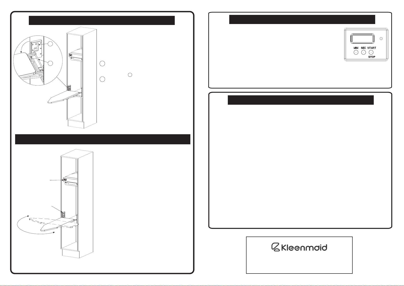
2
1
To open the Ironing Board, lift board
retainer and lower the board. To store
Ironing Board, follow the steps in reverse
order.
The Ironing Board has three working
heights. To adjust the board:
1 With the board in the horizontal position
hold the board with one hand near the
base (NOT BY THE NOSE) and support
the pivot rod 1 with the other hand.
2 Adjust the Ironing board to the desired
position by lifting the board by the pivot rod
(NOT BY THE NOSE) and moving it to
the required height.
NOTE: in order to store the Ironing board,
it may need to be in the lowest position
depending on your cabinet construction.
SWIVEL
BOARD
180O
3 POSITIONS
HEIGHT
ADJUSTMENT
Console
MANUFACTURED FOR:
BY:
ROBINHOOD LIMITED
6 ZELANIAN DRIVE, EAST TAMAKI
AUCKLAND, NEW ZEALAND
ISO9001 Certified
MAINTENANCE
YOUR LWK320 IRONING CENTRE KIT SET BOARD IS NOW FITTED WITH A HEAT RESISTANT
COVER.
TO AVOID DAMAGE TO THE MATERIAL
PLEASE DO NOT WASH THE COVER
The laminated surface of the unit may be
wiped clean with non abrasive household cleaner.
WARNING
1) Do not place EXCESSIVE WEIGHT (weight should not exceed 15kg) on the Ironing
Board when opened as it is designed to accept normal ironing use only.
2) Iron not to exceed 2360 Watt.
3) Allow iron to cool down before storing in the cabinet.
4) Empty water reservoir and turn off steam action prior to storing iron.
5) Turn power off when not in use.
6) Do not remove the board retainer.
7) The appliance is not intended for use by young children or infirm persons
without supervision.
8) Young children shall be supervised to ensure that they do not play with the
appliance.
9) The appliance is supplied with an approved power cable which must not be
changed. If the supplied cord of this equipment is damaged, it must only be
replaced by the manufacturer, its service agent or similarly qualified person in
order to avoid hazard.
10) Upon installation, ensure that the socket outlet or ON/OFF switch remains easily
accessible after installation.
DIGITAL TIMER OPERATING INSTRUCTIONS
1. As the unit is powered up, two series of beeps are given.
2. “00m00s” is displayed.
3. Press “MIN” button once to advance the minute section by 1
or hold down for an incremental increase in minutes.
4. (Optional) Press “SEC” button once to advance the second
section by 1 or hold down for an incremental increase
in seconds.
5. When there is a change in settings a beep is given.
6. To start or stop the timer anytime press the “START/STOP”
button.
7. When the timer is counting down the red LED is on.
8. When the timer reaches zero, power to the 3 pin socket and light is disconnected
and a series of beeps will sound. The timer will then revert to the original
settings. Press any key to stop the beep sound.
9. To reset the timer to zero press the “MIN” and “SEC” buttons simultaneously.
Popular Indoor Furnishing manuals by other brands

BIG FURNITURE WAREHOUSE
BIG FURNITURE WAREHOUSE Toronto DESTOROAK Assembly instruction

Teknik
Teknik Barrister Home 5418902 manual

Martha Stewart
Martha Stewart ZG-ZP-028-WH-GLD-MS instruction manual

emob
emob ELIAS BED-LIT 90 Assembly instruction

Habitat
Habitat Giulia 815000 manual

Herman Miller
Herman Miller Sayl manual

College Bed Lofts
College Bed Lofts Low Platform / High Rise Bed with Trundle Assembly instructions

Spacetronik
Spacetronik SPE-B118WW installation guide

burgbad
burgbad Style M1136 FITTING INSTRUCTIONS AND OPERATING MANUAL

The Land of Nod
The Land of Nod Wrightwood Twin-over-Twin Bunk Bed Assembly instructions

Otto
Otto AALBORG NEU AN-14 Assembly instructions

BROSA
BROSA OSTRO Assembly guide