Klimaire HM700 Series User manual

Electrode
Steam
Humidifier
klimaireINTL@klimaireINTL.com
+1.647.477.3333
+1.646.808.0240
KLIMAIRE International
www.klimaireINTL.com
HM700-Series
IOM Manual

INSTALLATION INSTRUCTIONS
HM700A1000
ELECTRODE STEAM HUMIDIFIER
INTRODUCTION
The HM700 is the most advanced residential steam humidifier
available and provides steady and reliable humidification for a
home. The humidifier is designed for connection to a steam
distributor installed in a supply air duct for humidity on
demand.
IMPORTANT
Read and save these instructions. This guide should
be kept by the installer, and the Homeownerms Guide
should be left with the equipment owner.
Included in the Box
rSteam Humidifier (HM700)
rDistribution Remote Mount Kit (HM700ADISTKIT)
rHumidiPRO Humidistat (H6062A1000)
rSteam Cylinder (one HM700ACYL2 included)
rRubber drain hose
rInstallation Instructions, Homeownerms Guide and
Quick Start Guide
Tools Needed
rScrewdriver
rWrench
rPliers
rShut-off water valve
rWater line (LDPE or Copper)
Humidifier Configuration
The HM700 is configured at the factory to operate under most
conditions without the need to change its configuration.
NOTE: Because the humidifier is factory configured for
optimal performance, Honeywell strongly
discourages changes to the jumpers or the
potentiometer; doing so will void the warranty
and could damage the humidifier. Contact
Honeywell Customer Care for further
information.
Before Installation
1. Ensure that available voltage and phase corresponds
with humidifier voltage and phase as indicated on
humidifierms specification label.
2. Ensure that the dedicated external fuse disconnect is of
sufficient size to handle the rated amps as indicated on
the specification label. Refer to local codes.
3. Ensure sufficient clearances will be available as
described in the Location section on page 5.
4. Ensure steam lines can be routed to duct distributor as
described in Steam Lines and Condensate Return
Instructions on page 8.
Table 1. Specifications.
Part Number Volts
Steam
Output
GPD KW Amps Phase
Max Ext
Fuse
Standard
Cylinder
Net/Full
Weight
lbs. (kg)
Dimensions
in inches
(L x W x H)
HM700A1000 110/120 11 1.4 12.0 1 15 A CYL2 15 / 20
(7.0 / 9.5) 11.5 x 6.75 x 21.5
220/240 22 2.8

HM700A1000
Fig. 1. Specification label location.
CAUTIO
N
Servicing
Disconnect main power before any servicing.
The plumbing and electrical compartments contain
high voltage components and wiring. Access should
be limited to authorized personnel only.
During and following operation of the humidifier, the
steam and components in contact with the steam
such as the steam lines, steam distributors, and
condensate lines can become hot and can burn if
touched.
Honeywell does not accept any liability for installations
of humidity equipment installed by unqualified
personnel or the use of
parts/components/equipment that are not
authorized or approved by Honeywell.
To maintain warranty, only Honeywell approved parts
and cylinders may be used in the operation of the
product.
CAUTIO
N
Electrical
All electrical work should be done according to local
and national electrical code.
Electrical connection to be performed by a licensed
electrician.
Unit must be powered by a dedicated GFI circuit.
CAUTIO
N
Plumbing
Plumbing to be performed by a licensed plumber.
Drain water from humidifier can be very hot. Do not
drain to public sink.
All plumbing work should be done according to local
plumbing code.
CAUTIO
N
Installation
Do not mount on hot surfaces.
Do not mount in area where freezing can occur.
Do not mount on vibrating surface.
Do not mount on floor.
The HM700 produces steam at atmospheric pressure.
No devices which could block steam output should
be connected to the steam outlet.
Steam lines must be installed so that no restriction can
produce backpressure in the humidifier.
CAUTIO
N
Water quality
The Honeywell HM700 requires a cold water
connection from your home's main water supply
between 30-100 PSIG. A throttle valve may be
necessary, and a water shut-off valve is
recommended for safety. Reverse Osmosis (RO)
and Deionized (DI) water must not be used. Water
conductivity is important to ensure the electrode
humidifier operates effectively. Honeywell
recommends 150-1200 S (microsiemens).
Parts and Accessories
The following parts and accessories are available and may have been included with your HM700 humidifier. The cylinder is the
only item that will need periodic replacement to maintain proper humidifier operation.
Table 2. Parts and accessories.
1
+SPH IR :EPPI ]1 MRRI WSXE
1%()-2'%2%(%
13()0
:3087 /;
,1% 72 <<<<<< <
4,%7) ,>
(%8) <<<<<<<<<
%
:3087 *0%+4(
*0%+4(
/;
%YXS%HETXMZI
0-78)(<
,91-(-*-)6
Part/Accessory Part Number
Replacement Cylinder HM700ACYL2
HumidiPRO Humidistat H6062A1000
Stainless Steel Distribution Remote Mount Kit HM700ADISTKIT
Replacement Drain Valve HM700ADVALVE
Replacement Fill Valve HM700AFVALVE
Replacement Transformer HM700ATX
Replacement PC Board HM700APCB
15 ft. Insulated Steam and Condensate Line Hose Kit HM700AHOSEKIT
Differential Pressure Switch for Air Proving 50027910-001

HM700A1000
How the Humidifier Works
The HM700 is an atmospheric steam generator that uses heat
generated by electrical current flowing between submerged
electrodes to generate steam. The HM700 is designed for on-
demand air humidification via a steam distributor.
STEAM GENERATION
pOnce the unit receives a demand signal and the safety loop
between terminal 1 and 2 is closed, the humidifier closes
the contactor and measures the electrical current.
pIf the demand is lower than the actual output the inlet valve
is kept closed and output is reduced by letting the water
level in the cylinder decrease by evaporation.
pIf demand is higher than the actual output, after a brief
delay the fill valve is activated and water flows into the fill
cup. Water from the fill cup flows into the bottom of the
cylinder through a hose connected to the drain valve
housing.
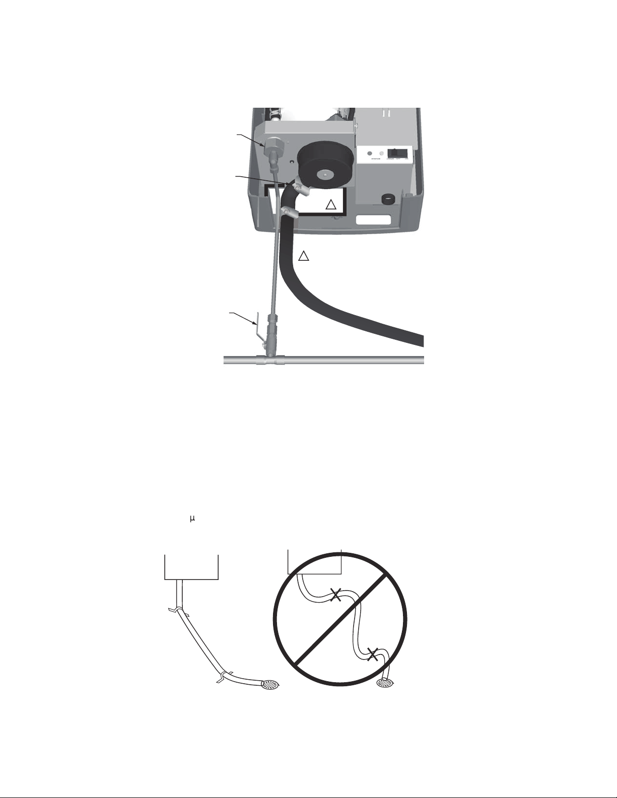
NOTE: The cylinder is gravity fed from the fill cup. If
backpressure from the steam line is too high it
will cause water to back up in the fill cup and
flow down the overflow line to the drain.
pAs soon as the water in the cylinder comes in contact with
the energized electrodes, current flows through the water.
The resistance of the water to the electrical charge
generates heat and in turn steam. The electrical current
(and steam output) increases as the level of water
increases, as more of the electrode becomes submerged.
The unit continues to fill until the current matches demand
or the high water sensor detects a high water level.
pThe HM700 repeats the fill and boil down cycle repeatedly
to match output to demand.
pOver time minerals in the water will adhere to the cylinder
electrodes. The humidifier will automatically fill to a higher
water level to maintain full capacity during the life of the
cylinder. Eventually because of scale formation it will no
longer be possible for the humidifier to reach its full
capacity. The HM700 software monitors this condition and,
when detected, will stop operating and flash the yellow
LED in a repeating sequence of 4 flashes.
DRAINS
pAs steam is produced, minerals are left behind, increasing
the conductivity of the water. The HM700 patented auto
adaptive cycle will monitor the water conductivity and
perform drains to maintain the water at optimal conductivity
for peak performance.
pThe auto adaptive cycle ensures cylinder life is maximized.
It does this by keeping the tightest control and most
efficient use of water during the entire cylinder life.
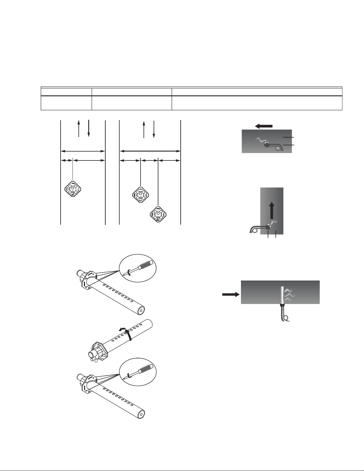
STEAM DISTRIBUTION
Steam generated by the humidifier may be introduced into the
air in several different ways. The most common method for
adding the steam into the air is to mount a steam distributor
tube in a supply air duct.
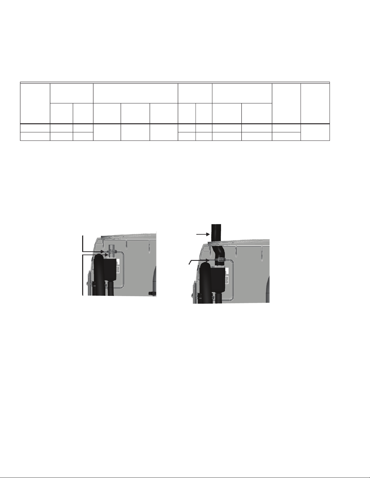
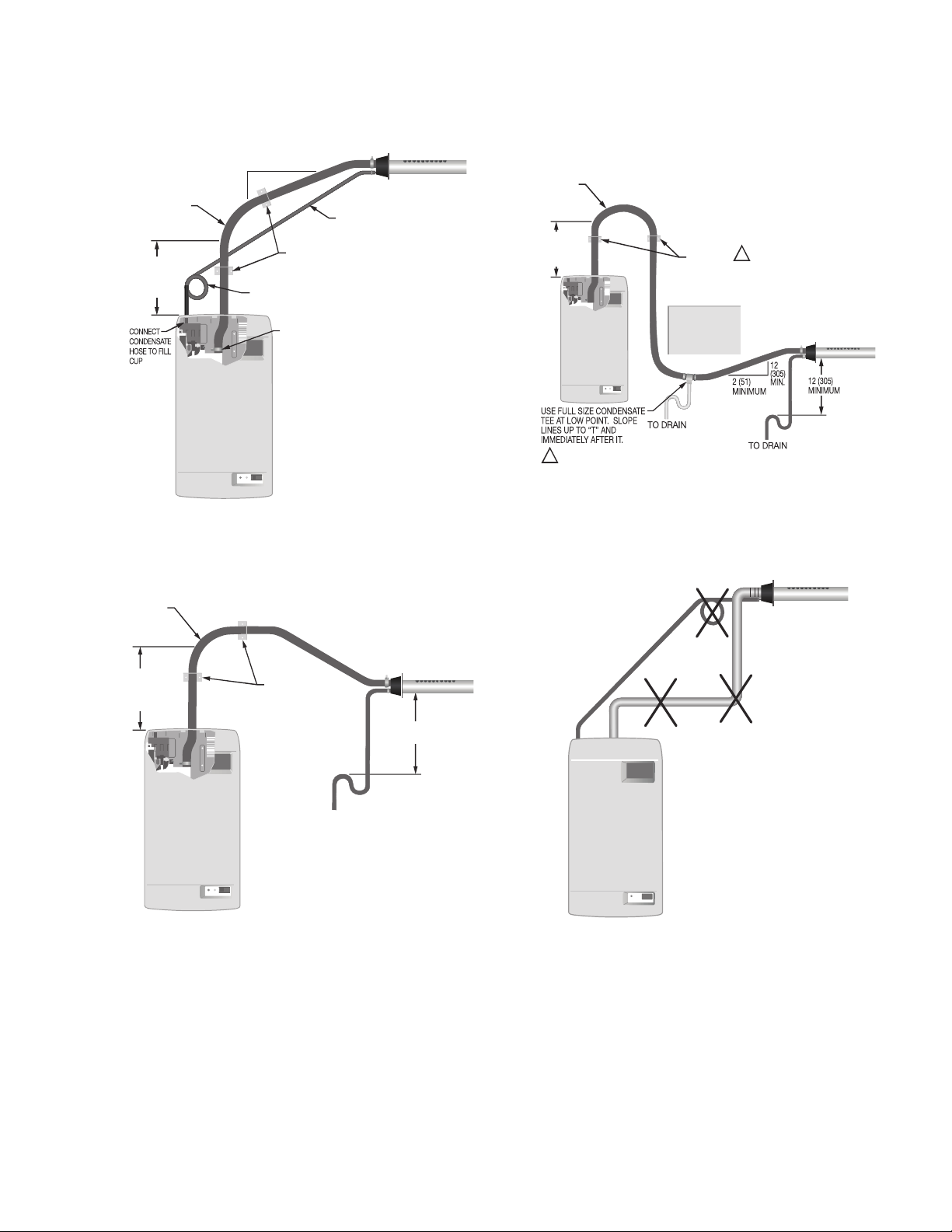
STEAM LINE
The steam line between the cylinder steam outlet and the
distributor serves two purposes: it is used as a conduit to
transfer the atmospheric steam from the humidifier to the
distributor, as well as providing a means to remove
condensate. See nSteam Lines and Condensate Return
Instructionsoon page 8 for information on selecting steam
lines.
CONDENSATE RETURN
Whenever steam is distributed condensate is formed in the
distribution system. Insulating steam lines is one important
way to reduce the amount of condensate formed. Steam lines
are sloped so that condensate does not collect in the lines and
create a restriction to steam flow. The condensate must be
collected and removed from the system so that it does not
build up and leak into the duct. Condensate can be returned to
the HM700 fill cup to reduce water waste or can be fed to
drain.

HM700A1000
Fig. 2. Typical HM700 Installation.
Measurements in inches (mm).
SIZING
IMPORTANT
The HM700 should only be installed if it has been
sized properly. Do not use square feet when sizing
a humidifier installation. Instead, cubic feet must
be used, since the humidity is filling a volume of
space (width x length x height). Also, take into
consideration the ntightnessoof a homems
construction.
The HM700 produces 11 gallons per day (GPD) when run on
120 V and 22 GPD when run on 240 V. See Figure 16 for
details on configuring the HM700 to run on a different voltage.
Table 3 contains AHRI recommendations for humidity
requirements and Table 4 shows what humidifiers and output
configuration will satisfy the humidification requirements.
Table 3. AHRI Recommended Humidity (in gallons per day).
348-32%0
6,91
,91
'
2%
%4
+J
6J
2%
,1
3** 32
238):'322)'8-327,3;2
)<8)62%0
1
1-2-191,)-+,8
7'6);7
1-2-191
13928-2+
78)%1
(-786-&98-32
'3286307
4091&-2+
)0)'86-'%0
1-2-191
Construction
Type 8,000 ft312,000 ft316,000 ft320,000 ft324,000 ft328,000 ft332,000 ft3
Tight 3.3 4.3 5.4 7.5 9.6 11.7 16
Average 7.6 9.6 11.8 16 20.3 24.4 33
Loose 11.7 14.9 18.1 24.5 30.8 37.1 50

HM700A1000
Table 4. Steam humidifier(s) necessary for application.a
aIn the table above, 11 GPD indicates a steam humidifier configured to run on 120 V and 22 GPD indicates a steam humidifier
configured to run on 240 V.
LOCATION
Mount on a suitable wall or vertical surface. Do not sit the unit
on the floor. Allow clearances required for plumbing and
electrical connections. Clearance dimensions shown are for
reference only and are the minimum required for maintenance
of the humidifier. Consult local and national codes before final
location and installation. Honeywell does not accept
responsibility for installation code violations.
pInstall only in areas with ambient temperature 41 to 104 °F
(5 to 40 °C) and relative humidity 5 to 95 %.
pWhen possible install below the steam distributor. Take
care to provide proper steam line routing and proper
condensate traps.
pDO NOT locate the humidifier any further then absolutely
necessary from the steam distributor location as net output
will be reduced as a result of heat loss through the steam
line.
pWhen possible, mount the HM700 humidifier at a height
convenient for servicing.
NOTE: Do not mount on hot surfaces, where freezing
can occur, vibrating surface, or floor.
Mounting with Keyholes
1. The HM700 humidifier is wall mounted using a keyhole
located on the back of the unit cabinetry.
2. Use #8 x 2 in. (5 cm) screws mounted into 2x4 studs or
better. 2 screws are needed, one for hanging the unit
and one for securing so it will not lift off the keyhole.
3. Install the top screw so that 1/4 in. (6 mm) is exposed.
Raise the unit and place the screw head through the
keyhole.
4. Make sure the unit is level and then insert and tighten
the second screw through the bottom hole. Tighten the
top screw. See Fig. 3.
NOTE: Use screws longer than 2 in. (5 cm) if drywall or
other spacer is present.
Fig. 3. Mounting with keyholes.
Construction
Type 8,000 ft312,000 ft316,000 ft320,000 ft324,000 ft328,000 ft332,000 ft3
Tight 11 GPD 11 GPD 11 GPD 11 GPD 11 GPD
11 GPD (x2)
or
22 GPD (x1)
11 GPD (x2)
or
22 GPD (x1)
Average 11 GPD 11 GPD 22 GPD 22 GPD 22 GPD
11 GPD (x3)
or
22 GPD (x2)
11 GPD (x3)
or
22 GPD (x2)
Loose 22 GPD 22 GPD 22 GPD
11 GPD (x3)
or
22 GPD (x2)
11 GPD (x3)
or
22 GPD (x2)
11 GPD (x4)
or
22 GPD (x2)
11 GPD (x5)
or
22 GPD (x3)
-278%007)'32(
7'6);%*8)6
,%2+-2+
,91-(-*-)6 <-2'1
;33(7'6);7
-27)687'6);0)%:-2+
-211)<437)(
,%2+92-88,)2
8-+,8)27'6);
<3638,)6
7869'896%0
1)1&)6
/)=,30)
1
,30)

HM700A1000
PLUMBING
Fig. 4. Water supply and drain connection.
IMPORTANT
rAll water supply and drain line connections should be
installed in accordance with local plumbing codes.
rDrain water is automatically cooled to 140 °F (60 °C)
when HM700 cycles a drain. When the manual drain
switch is used, temperature may be higher. The drain
material (tube and drain) must be rated for 200 °F
(93 °C).
pSupply water should be between 30 to 100 PSIG. A throttle
valve may be used if necessary.
pDo not use reverse osmosis or de-ionized water. Supply
water should be between 150-1200 S (microsiemens) for
optimal conductivity.
pSupply water should be cold, 34 to 68 ºF (1 to 20 ºC).
pInstall water shut off valve before humidifier to facilitate
servicing.
pThe drain line should not end in a sink used frequently by
personnel, or where plumbing codes prohibit it. Route to a
floor drain or equivalent for safety reasons.
pDrain line should be routed to allow free flow of water.
Ensure adequate slope, no traps, and no kinks. A restricted
drain can cause cylinder water to over concentrate and
result in poor operation.
pIf a drain is not located near the humidifier use a
condensate pump rated for hot drain water.
Fig. 5.
-2113(
%0;%=7-278%00%
;%8)67,983**:%0:)
97)-2'3146)77-32
*-88-2+-2'09()(83
'322)'8;%8)679440=
0-2)8392-80(4)40%78-'
36'344)6
97)-23('344)683
;-8,-2*813*,91-(-*-)6
1
*-00%2((6%-20-2)7'%2%073&)
6398)(8,639+,34)2-2+-2&%'/
3*'%&-2)8
1

HM700A1000
Steam Distributor
The HM700 requires a steam distributor installed in the
supply-side of ductwork. The HM700 can distribute steam into
a ventilation duct using the distributor shown in Table 5.
The steam distributor should be installed as close as possible
to the humidifier. Short steam distribution lines minimize
condensate loss and the possibility of generating
backpressure in the steam distribution line.
Table 5. Steam distributor.
Fig. 6.
Fig. 7.
Fig. 8. Distributor installed horizontally
in a horizontal duct.
Fig. 9. Distributor installed horizontally in a vertical duct.
Rotate the distributor 45º so that steam is discharged
toward the center of duct, in the direction of the air flow.
Fig. 10. Distributor installed vertically in a horizontal duct.
This configuration is not recommended.
Part Number Description Notes
HM700ADISTKIT Stainless Steel Distribution
Remote Mount Kit
Includes a steam distributor, 5 ft. insulated steam hose, condensate
hose, and installation hardware.
;
;
;
1-2;!
,
; ; ;
1
1
8962
ß
´ß
1
%-6*03;
1
%-6*03;
1
%-6*03;

HM700A1000
Steam Lines and Condensate Return Instructions
The following instructions must be followed for installation of steam lines for the HM700. Failure to use recommended material
and exceeding maximum recommended length in Table 6, or failure to follow any other steam line installation instructions will
result in improper operation and could void the warranty.
Table 6. Recommended Steam Line Material for HM700 Duct.
*Th
e use of steam line other than copper, stainless steel tube or Honeywell supplied steam line will void the warranty and may
adversely affect the operation of the humidifier.
*Wh
en using copper or stainless steel tubing (other than the supplied tubing), insulation is recommended due to high
temperature safety as well as reduced condensate.
To return condensate for HM700, insert copper tube (supplied with equipment) half way into the condensate opening of the fill cup
along with the spring clamp (supplied with equipment).
Insert the condensate hose into the condensate return hole at the top of the HM700, and over the copper tube. Fasten in place
with the spring clamp.
Fig. 11. Condensate return.
MAIN RULES FOR ATMOSPHERIC STEAM LINES
pSteam lines must not have any restrictions which could result in back pressure.
pFollow recommended materials, size and length, see tables.
pInstall steam line in a vertical (upwards) fashion from the HM700 to the distribution nozzle. Consult Figures 12-14 for other
installation options.
pInsulate with 1.0 in. (2.5 cm) pipe insulation.
pTrap condensate (Use full size lTmfor Traps)
pDo not over tighten hose clamp at cylinder steam outlet. The maximum torque is 12 in-lbs.
pSupport steam line so weight is not on cylinder.
pCondensate traps must be a minimum of 6 in. (15 cm) in height or duct static pressure +2 in. (5 cm), whichever is greater.
pTrapping by P-trap or pigtail. Support line as necessary to ensure it remains free of kinks.
Voltage
Steam Output Material*
Maximum
Steam Line
Length Possible Losses
Minimum
Airflow
CFM
Max
Static
Pressurelbs/hr (kg/hr)
Steam
Hose
MED-L
Copper
Tube
Stainless
Steel
Tube ft (m) lbs/hr (kg/hr)
110/120V 3.85 (1.75) 7/8 in. 3/4 in. 0.875 x
0.049W
7 (2) 0.5 (0.2) 115 3.0 in. w.c.
220/240V 7.7 (3.5) 12 (3.5) 1.5 (0.7) 230
1
746-2+'0%14
·3('344)689&)
746-2+
'0%14
-27)68,37)3:)6
'344)689&)%2(
*%78)2;-8,
746-2+'0%14

HM700A1000
Steam Line Installation Examples
Fig. 12. Steam distributor above humidifier (hose).
Measurements in inches (mm).
Fig. 13. Steam distributor below humidifier (hose).
Measurements in inches (mm).
Fig. 14. Steam distributor below humidifier with
obstruction (hose). Measurements in inches (mm).
Fig. 15. Common steam line installation errors.
Measurements in inches (mm).
1
1-2-191
&)*36)
%2=&)2(
1-2-191
6%(-97 '32()27%8)
0-2)
7944368
&6%'/)87
1-2-191
'322)'8
78)%1
,37)83
'=0-2()6
'32()27%8)
0-2)
1-2-191
1
7944368
&6%'/)87
'32()27%8)
86%4
83(6%-2
1-2-191
6%(-97
1-2-191
&)*36)
%2=&)2(
1
3&7869'8-32
1-2-191
6%(-97
1-2-191
&)*36)
%2=&)2( 7944368
&6%'/)87
,37);-0073*8)23:)68-1)4634)67944368-72)')77%6=
1
23
'32()27%8)
86%4%8
:)68-'%0
86%27-8-32
78)%10-2)
2387034)(
'32()27%8)
86%4238
&)03;
(-786-&9836

HM700A1000
ELECTRICAL
CAUTIO
N
Wiring to be performed by a licensed electrician. This unit must be installed on a GFI Circuit.
CAUTIO
N
Equipment Damage Hazard
Failure to wire the humidifier in accordance with the wiring instructions could cause permanent damage.
Such errors will void the warranty.
WARNIN
G
HM700A Humidifier must be installed using a dedicated 15 amp circuit breaker and hardwired directly to comply
with UL product listing. All wiring must be done per governing electrical codes.
Electrical line cord plugs can overheat and result in risk of damage to property and/or personal injury. Note: Product
warranty will be voided if these instructions are not followed.
CAUTIO
N
JUMPER WIRE INSTALLATION
pDO NOT install mains voltage wire (hot or neutral) into 120 or 240 terminal.
pDO install mains wires into L1 terminal (hot) and P terminal (hot/neutral).
pDO install jumper from P to 120 or 240 terminal (according to mains voltage).
Installation Steps
1. Unit requires a dedicated circuit with GFI protection. Bring circuit to a disconnect near the device to protect from electrical
shock when servicing.
2. Hard wire humidifier to disconnect according as shown at right.
3. Install factory-supplied jumper between the P terminal and the terminal that corresponds to supply voltage.
4. Remove green wire attached to case body and drain valve (remove canister for access).
5. Clip ground wire as close to drain valve as possible and remove excess.
1
:%' 0 2% 4
:%'
.YQTIV
0 2% 4
.YQTIV
:%' 0 2% 4
:%'
.YQTIV
0 2% 4
.YQTIV
1

HM700A1000
Fig. 16. Primary power connection.
NOTES:
rHoneywell requires the use of a GFI circuit on this device to protect the homeowner from electrical shock.
rWhen installed correctly, the green wire should be removed from the drain valve. The green wire comes pre-installed
from the factory to protect the homeowner in case of an improper installation or when it is not possible to retrofit a GFI
circuit. See Fig. 24 for the location of green wire on the drain valve.
rEnsure that adequate power is available to carry full humidifier amp draw as indicated on the specification label.
rDo not use neutral wire as a ground; connect a dedicated ground to ground termination.
rAll wiring to be in accordance with national and local electrical codes.
,38
,38
+6392( 4
0
+6392(
)
<
8
-
2
8
:%'4,%7)
:%'4,%7)
2)986%0
,38
+6392( 4
0
+6392(
238)'322)'8:%'
¶,38·830
348-32%0
348-32%0
238)43;)6;-6)7
'%2%073&)6398)(
8,639+,34)2-2+-2
&%'/3*'%&-2)8
1

HM700A1000
EXTERNAL CONTROLS
Fan Interlock Wiring with HumidiPRO
When distributing steam into a duct, there could be a call for
humidity when there is no air flow. The HM700 with
HumidiPRO control or some other thermostat (such as the
Honeywell Prestige of VisionPRO®) can be used to enable a
fan on a call for humidity. If using another thermostat, consult
that controlms manual for wiring instructions to enable the fan
with a powered humidification device.
NOTE: Humidifier will not start producing steam until
fan security loop is closed.
This information is relevant to all controls, factory supplied or
otherwise. For wiring use minimum 18 AWG solid wire and
keep as short as possible.
Humidity Control
pCan be located either in return air duct (preferred) or in
room being humidified.
pAvoid placing near discharge diffuser of humidified air.
pMount in area representative of room humidity (drafts,
doorways, sunlight, or an overhang such as a shelf can
affect reading).
Optional Outdoor Temperature Sensor (not shown; included
with HumidPRO)
pMount outside in area representing air temperature.
Fig. 18. Wiring the steam humidifier with a mechanical
thermostat.
NOTE: If a Prestige, VisionPRO, Lyric (or similar) are used to control humidity, wire the two HUM contacts to terminals 1 and 2
on the HM700. With the jumper in place between terminals 1 and 8 on the HM700, only these two wires are necessary
to control humidity. Be sure to configure the control to force fan on with a call for humidity, or run on a heat cycle if the fan
enable wiring is not used.
,:%'
8,)61378%8
6
'
9
9
7
7
+=;66G
+=;6'
6,91
,91
'
2%
%4
+*
6*
2%
1
398(336
7)2736
%-6463:-2+
36.914)6
,:%'
8,)61378%8
6
'
9
9
7
7
+=;66G
+=;6'
,91
'
2%
%4
+*
6*
2%
1
238)
%-6463:-2+
36.914)6

HM700A1000
START UP
Installation Check
Before turning on power to the HM700, inspect the installation to ensure that it was carried out correctly.
Fig. 19. Installation check.
CAUTIO
N
Equipment Damage Hazard
Do not leave the On/Off/Drain switch in the drain
position for more than one complete drain cycle. The
drain valve solenoid may heat up and result in damage
to the valve and its wiring.
Do not attempt to drain with no water in system.
On/Off
The HM700 is factory-configured to operate as an On/Off
humidifier. It will run when 24 VAC from terminal 1 is fed back
into terminal 2 through an On/Off humidistat and other
security devices in series.
*97)((-7'322)'8
'366)'8:308%+)%147
4,%7)4)674)'0%&)0
348-32%0
13928-2+
92-80):)0
7'6);7-283
7869'896%0
1)1&)6
78)%10-2)
%()59%8)7034)
236)786-'8-327
23/-2/7-2,37)
'32()27%8)86%47
32032+6927
,91-(-8='328630
-26)8962(9'836
03'%8-32;,-',
6)46)7)287,91-(-*-)(
74%')23(6%*87238
&=(336238&=(-**97)6
-20-2)1-2-19183;-8,-2*8147-+
74)'0%&)0
%-6+%4
486%4
;-8,-2'1
1-2-191(634
&)2(3638,)6
3&7869'8-32
<(9'8,)-+,
8
*631*%236
86%27-8-32
*))811-2-191
*))81-2-191
(9'8
,)-+,8
'1
1-2-191
,-+,0-1-8
323**
348-32%0
-27)6-)7&)8;))2
8)61-2%07%2(
.914)6&)8;))28)61-2%07
%2(1978&)6)13:)(
1
(6%-20-2)7,390(&)6398)(83%003;*6))*03;3*
;%8)6)2796)%()59%8)7034)2386%47%2(23/-2/7

HM700A1000
Start Up Procedure
1. Examine the humidifier and installation for damage
and/or improper installation.
2. Ensure the cylinder is properly seated in the drain valve
and that the electrode plugs are pushed all the way
down on the cylinder pins.
3. Ensure that the front cover is in place and secured with
its retaining screws.
4. Open the supply water shut off valve.
5. Turn on the main power using the installed disconnect.
WARNIN
G
Personal Injury Hazard.
Damaged or improperly installed units must not be
operated. Damaged or improperly installed units may
present a danger to persons and property.
6. Turn the On/Off switch on the front of the humidifier to
On.
pThe humidifier will perform a self-diagnostic
sequence during which the LEDms and internal
components will be momentarily activated. See
nLED Status Lightsoon page 15 for an explanation
of the LEDs and sequences.
pIf an error is detected during the self-diagnostic
sequence the humidifier will not start. The yellow
status LED will flash in sequence to indicate the
detected fault. See Tables 7 and 8 for information
on diagnosing and correcting faults.
pAfter the system test the humidifier is in normal
operation mode.
7. Check and adjust the control setpoint on the control and
high limit humidistat.
8. When the external humidistat generates a demand for
humidity and the security loop is closed the green
humidifying LED on the front of the humidifier will light
up, the power relay on the control board will engage, the
fill valve will activate (after a delay) and the cylinder will
slowly fill with water.
NOTE: While the cylinder is filling with water there
should be no water flowing down the drain. If
water is flowing down the drain it can indicate
excessive backpressure or a leaking drain valve.
See Troubleshooting.
9. If a fan enable relay is used, the green LED will continue
to flash until the air proving closes. Once the air closes,
the flashing green LED will become solid and the
humidifier will start steam production as described in
step 8.
10. It can take 5 q10 minutes for the water to be heated up
by the submerged electrodes and for steam to be pro-
duced.
NOTE: If operated on low conductivity water it may take
several hours for the HM700 to reach full output
capacity. This is normal. During this time the
humidifier will not perform any drains and the
conductivity of the water in the cylinder will
increase. To expedite this process, add a
1/4 teaspoon of salt to the cylinder. This will
immediately increase water conductivity and
initiate heating.

HM700A1000
OPERATION
LED Status Lights
The HM700 user interface includes 2 LEDs that provide
information about the humidifier status.
Fig. 20. LED status indicator lights.
Yellow and Green LED Flashing
Indicates there is no request for humidity.
Yellow LED Flashing
Fault detected, humidifier has stopped operating. Count
the number of flashes and see Table 8 for info.
Green LED Flashing
Indicates the humidifier is powered, but there is not a
request for humidity. Security loop (1-2) is open.
Yellow LED On
Indicates that water level is high.
When the yellow LED is steady on (not flashing) it indi-
cates that the high water sensor has interrupted filling of
the cylinder. The LED is on for information only and
unless it persists for an extended period of time, it does
not require any action.
Green LED On
Indicates steam is being produced.
Selecting a Relative Humidity
Setpoint
The optimum humidity setpoint depends on the reasons that a
space is being humidified. The nASHRAE Handbook HVAC
Applicationsorecommends specific design relative humidity for
specific applications.
Health and Comfort qThe benefit of humidity is most
pronounced for health and comfort in the 40-60% range. A
humidity setting of 45-50% is recommended for this purpose
to prevent over humidifying.
Temperature Setback qIn cold climates it is often necessary
to reduce the humidity level in a conditioned environment to
prevent build-up of condensation on the inside of exterior
walls, windows, and trim. It is highly recommended that the
humidity setback function of the HumidiPRO control be used
under these conditions to prevent damage from condensation.
The digital control with an outdoor temperature sensor
installed will automatically setback the humidity setpoint to
correspond with outdoor temperature.
1
78%897 (6%-23**32
=)003;+6))2

HM700A1000
Fig. 21. Humidifier components.
78)%1
3980)8
'32()27%8)
6)8962
*-00'94
(6%-2:%0:)(6%-2'%2%0
*-00:%0:)
'=0-2()6
'=0-2()6
409+
,-+,;%8)6
7)2736409+
323**(6%-2
7;-8',
'328630
&3%6(
43;)66)0%=
,-+,:308%+)
8) 6 1 -2 % 0
&03'/
86%27*361)
6
'328630
8) 6 1 -2 % 0
786-4
1
Component Function
Condensate Return Provides a connection to return condensate to humidifier.
Control Terminal Strip Terminal strip for connecting external controls to humidifier and interfacing with other equipment.
Cylinder Plug Power connectors to electrodes in cylinder.
Cylinder Holds electrodes in water. Current between electrodes generates heat used to generate steam.
Drain Canal Combines cylinder drain water and fill cup overflow into a single drain outlet.
Drain Valve Drains water from humidifier.
Control Board Controls all functions of the humidifier operation and provides input and output connections to
humidifier components.
Fill Cup Provides an air gap for backflow prevention.
Fill Valve Controls flow of water into humidifier.
High Voltage Terminal
Block
Primary power connection from remote disconnect to humidifier.
High Water sensor Plug Used to detect max water level in cylinder.
On/Off/Drain Switch Turns power on/off to humidifier controller and drains the cylinder for servicing. Note: Turn off
humidifier disconnect to shut off primary power to the humidifier.
Power Relay Turns on/off power to cylinder electrodes based on a signal from the humidifierms controller (mounted
on control board).
Steam Outlet Connect to steam line with steam hose.
Transformer Steps primary voltage down to 24 VAC for the controller and internal components such as the fill valve
and drain valve.

HM700A1000
MAINTENANCE AND SERVICING
Required Maintenance
The HM700 humidifier has been designed to require very little
maintenance. Regular maintenance consists of checking the
humidifier to ensure it is in good condition, replacing the
cylinder when the software advises that the cylinder is spent
and cleaning out the drain valve whenever the cylinder is
replaced.
CYLINDER SPENT FAULT
When the cylinder is spent the HM700 will stop operating and
the yellow LED will flash in a repeating pattern of 4 flashes.
See Table 8 on page 22 for more information on other flash
sequences. At this time the cylinder must be replaced.
The steam cylinder is disposable and must be replaced at end
of cylinder life. Cylinder life is dependent on water supply
conditions and humidifier usage.
CAUTIO
N
Failure to replace the cylinder at the end of
cylinder life will result in improper operation and
may result in damage to the humidifier. Honeywell
is not responsible for any damages resulting from,
or attributed to, the failure to replace a spent
cylinder (see Manufacturerms Warranty).
NOTE: Honeywell recommends keeping a replacement
cylinder in stock throughout the humidification
season. This will prevent possible downtime
when the humidifier reports cylinder end of life.
REPLACEMENT CYLINDER
The label on the existing cylinder identifies the cylinder type in
its top left corner. When ordering a cylinder always quote the
three or five digit model number on the label, the humidifierms
serial number and the humidifiers voltage. Serial number and
voltage are located on the specification label on the left side of
the humidifier.
Fig. 22. HM700 cylinder (HM700ACYL2).
1
)0)'863()-28)62%0
13928-2+43-28
,-+,;%8)67)27364-2,%7
%40%78-''300%6%6392(-8
'322)'836%2+),-+,;%8)6
7)2736;-6),)6)
78)%13980)8
7)'96)78)%1,37)83
3980)8;-8,,37)'0%14
)0)'863()4-2
'322)'8'3036'3()('=0-2()6
409+7834-2;-8,'366)7432(-2+
'30360%&)08,)746-2+03%()(
409+7,390(*-8729+0=328,)4-2
6)40%')-*0337)36%2=7-+273*
(%1%+)
0%&)0
-()28-*-)7'=0-2()6-2*361%8-32
%
073-2'09()77%*)8=-2*361%8-32
%2('328%'87

HM700A1000
Removing the Cylinder
WARNIN
G
Disconnect main power at the external disconnect
before any servicing.
The inside of the humidifier cabinet contains high
voltage components and wiring. Access should be
limited to authorized personnel.
1. Drain the existing cylinder by switching the On/Off/Drain
switch to the Drain position. Let the humidifier drain until
no more water is flowing out to drain (usually not more
than 10 minutes).
2. Turn the humidifier On/Off/Drain switch to off.
3. Close supply water shut off valve.
4. Turn off power to the humidifier with the external discon-
nect.
5. Remove the two screws securing the front cover.
6. Remove the cylinder plugs from the cylinder pins by
pulling vertically.
7. Using a flat screwdriver loosen the hose clamp where
the hose is connected to the cylinder.
8. Tip the top of the cylinder forward to pivot it out of the
steam hose. When free of steam hose lift the cylinder
out.
NOTE: The HM700 has a re-usable tie strap to secure the
cylinder for transit as well as home installation.
This must be removed or loosened to remove the
cylinder. Secure when new cylinder is installed.
Fig. 23. Cylinder removal.
,37)'0%14
'=0-2()6409+
0-*8:)68-'%00=
323**(6%-27;-8',
'=0-2()6
'3:)67'6);7
8-08'=0-2()6
*36;%6(83'0)%6
,37)%2(8,)2
0-*8*631(6%-2
:%0:)
8-08'3:)6
*36;%6(83
6)13:)
1

HM700A1000
Drain Valve Cleaning
Always clean the drain valve before installing a new cylinder.
Scale from the spent cylinder may have fallen into the drain
valve and could prevent its proper operation. To properly clean
the drain valve it must be removed and disassembled.
1. Disconnect spade terminals from the drain valve.
2. Remove the two screws holding the valve to the drain
pan.
3. Squeeze the tabs of the spring clamp holding the hose
to the drain valve and slide it up the hose. Pull hose
from drain valve. Lift the drain valve from the drain pan.
4. Unsnap red coil cap on solenoid and remove the sole-
noid from the valve.
5. Loosen brass nut holding actuator to plastic housing
with a wrench and disassemble actuator.
6. Clean actuator components and valve housing (inlet
port, outlet port, and cylinder port). Put new o-ring that
was supplied with new cylinder into valve.
7. Reassemble actuator making sure tapered end of
spring is oriented as shown in Fig. 25. Tighten brass nut
1/4 turn past hand tight.
8. Clean out end of hose and reattach to valve. Slide hose
clamp back in place and place valve into drain pan.
9. Secure valve with 2 screws to drain pan.
Fig. 24. Drain valve.
Fig. 25. Drain valve actuator assembly.
Installing the New Cylinder
CAUTIO
N
Make sure the new cylinder is a HM700ACYL2. Use
of any other model or remanufactured cylinders
will void the HM700 warranty.
1. Insert cylinder into drain valve. Tilt cylinder forward and
fit end of steam hose to steam outlet. Tip cylinder back
into place.
2. Tighten hose clamp being careful not to over tighten and
crush the plastic cylinder steam outlet.
3. Attach color-coded cylinder plugs to the corresponding
color-coded cylinder pin. Push down completely.
Connect high water sensor plug. Spring-loaded plugs
should fit snuggly onto the cylinder pin. Replace if they
are loose or damaged.
4. Re-fasten tie strap.
5. Replace the humidifier cover and secure with two
screws.
6. Turn on power to humidifier with the external
disconnect.
7. Open supply water shut off valve.
8. Turn the humidifier On/Off /Drain switch to On.
Extended Shutdown
Should it be required to disconnect power to the humidifier for
a period of extended shut-down, always drain the cylinder first.
1. Switch the On/Off/Drain Switch to the Drain position.
2. Wait until the humidifier is completely drained (usually
takes less than 10 minutes).
3. Turn the On/Off /Drain switch to the off position.
4. Shut off power to the humidifier with the external
disconnect.
5. Close the supply water shut-off valve.
NOTE: As long as the HM700 is powered, it will
automatically drain the cylinder when there has
not been a call for humidity for an extended
period of time. This feature will reduce or prevent
the possibility of corrosion of the electrodes and
the accumulation of algae and bacteria growing
in the cylinder. The cylinder will remain empty
until there is a call for humidity at which time the
fill valve will open and refill the cylinder. The unit
will go through its normal process for optimum
operation.
STARTING AFTER EXTENDED SHUTDOWN
1. Check to see the humidifier has not been damaged and
the installation has not been altered. See nStart Up
Procedureoon page 14.
2. Turn on the power to the humidifier with the external
disconnect.
3. Turn the On/Off/ Drain switch to the Drain position.
4. Wait until there is no water flowing to drain. It usually
takes less than 10 minutes.
5. Follow the start up procedure on page 14.
'=0-2()64368
%2(36-2+
+6392(
;-6)
730)23-
(
74%()
'322)'8367
&6%77298
%'89%836
7'6);7
,37)%2(
,37)'0%14
1
1
70)):)%2(
730)23-(
746-2+
238)36-)28%8-32
4092+)6
%'89%836
Table of contents
Languages:
Other Klimaire Humidifier manuals