Klimaire HM700-FIAC User manual

Electrode
Steam
Humidifiers
klimaireINTL@klimaireINTL.com
+1.647.477.3333
+1.646.808.0240
KLIMAIRE International
www.klimaireINTL.com
HM700-Fiac
IOM Manual

INSTALLATION INSTRUCTIONS
Electrode Humidifier Cylinder
Replacement
HM700ACYL2
CAUTION
Before Servicing
1. Disconnect main power source before
accessing internal compartments.
2. The plumbing and electrical compartments
contain high voltage components and wiring.
Access should be limited to licensed HVAC
professionals only.
3. During and following operation of the
humidifier, the steam components in contact
with the steam such as the cylinder, steam
lines, steam distributors, and condensate lines
can become hot and burn if touched. Please
consult HM700 Installation manual for
reference.
4. Installations of humidity equipment installed by
unqualified personnel or the use of non-
Honeywell parts and components will void
warranty.
MAINTENANCE
The HM700 humidifier has been designed to require very
little maintenance. Regular maintenance consists of
checking the humidifier to ensure it is in good condition,
replacing the cylinder when the software advises that the
cylinder is spent, and cleaning out the drain valve
whenever the cylinder is replaced.
Included in the Box
pReplacement Cylinder
pNew O-Ring
pInstallation Instructions
Tools Needed
pScrewdriver
pPliers
pWrench
SPECIFICATIONS
Product Name: HM700 Replacement Canister
Product Number: HM700ACYL2
Dimensions: See Fig. 1.
Fig. 1. Dimensions in in. (mm).
Cylinder Spent Fault
When the cylinder is spent the HM700 will stop operating
and the yellow LED will flash in a repeating pattern of 4
flashes. At this time the cylinder must be replaced.
The steam cylinder is disposable and must be replaced
at end of cylinder life. Cylinder life is dependent on water
supply conditions and humidifier use.
1
;%8)6-20)8
%2((6%-2
¼
78)%13980)8
3(

ELECTRODE HUMIDIFIER CYLINDER REPLACEMENT
CAUTION
Equipment Damage
Failure to replace the cylinder at the end of
cylinder life will result in improper operation and
may result in damage to the humidifier. Honeywell
is not responsible for any damages resulting from,
or attributed to, the failure to replace a spent
cylinder.
NOTE: Honeywell recommends keeping a replace-
ment cylinder in stock throughout the humid-
ification season. This will prevent possible
downtime when the humidifier reports cylin-
der end of life.
Fig. 2. HM700 Cylinder
Removing the Cylinder
WARNIN
G
Disconnect main power at the external
disconnect before any servicing.
The inside of the humidifier cabinet contains high
voltage components and wiring. Access should be
limited to authorized personnel.
1. Drain the existing cylinder by switching the On/Off/
Drain switch to the Drain position. Let the humidifier
drain until no more water is flowing out to drain
(usually not more than 10 minutes).
2. Turn the humidifier On/Off/Drain switch to off.
3. Close supply water shut off valve.
4. Turn off power to the humidifier with the external
disconnect.
5. Remove the two screws securing the front cover.
6. Remove the cylinder plugs from the cylinder pins by
pulling vertically.
7. Using a flat screwdriver loosen the hose clamp
where the hose is connected to the cylinder.
8. Tip the top of the cylinder forward to pivot it out of
the steam hose. When free of steam hose lift the
cylinder out.
NOTE: The HM700 has a re-usable tie strap to
secure the cylinder for transit as well as
home installation. This must be
removed or loosened to remove the cyl-
inder.
1
)0)'863()-28)62%0
13928-2+43-28
,-+,;%8)67)27364-2,%7
%40%78-''300%6%6392(-8
'322)'836%2+),-+,;%8)6
7)2736;-6),)6)
78)%13980)8
7)'96)78)%1,37)83
3980)8;-8,,37)'0%14
)0)'863()4-2
'322)'8'3036'3()('=0-2()6
409+7834-2;-8,'366)7432(-2+
'30360%&)08,)746-2+03%()(
409+7,390(*-8729+0=328,)4-2
6)40%')-*0337)36%2=7-+273*
(%1%+)
0%&)0
-()28-*-)7'=0-2()6-2*361%8-32
%073-2'09()77%*)8=-2*361%8-32
%2('328%'87

ELECTRODE HUMIDIFIER CYLINDER REPLACEMENT
Fig. 3. Cylinder Removal
Drain Valve Cleaning
Always clean the drain valve before installing a new
cylinder. Scale from the spent cylinder may have fallen
into the drain valve and could prevent its proper operation.
To properly clean the drain valve it must be removed and
disassembled.
1. Disconnect spade terminals from the drain valve.
2. Remove the two screws holding the valve to the
drain pan.
3. Squeeze the tabs of the spring clamp holding the
hose to the drain valve and slide it up the hose. Pull
hose from drain valve. Lift the drain valve from the
drain pan.
4. Unsnap red coil cap on solenoid and remove the
solenoid from the valve.
5. Loosen brass nut holding actuator to plastic hous-
ing with a wrench and disassemble actuator.
6. Clean actuator components and valve housing (inlet
port, outlet port, and cylinder port). Put new o-ring
that was supplied with new cylinder into valve.
7. Reassemble actuator making sure tapered end of
spring is oriented as shown in Fig. 4. Tighten brass
nut 1/4 turn past hand tight.
8. Clean out end of hose and reattach to valve. Slide
hose clamp back in place and place valve into drain
pan.
9. Secure valve with 2 screws.
Fig. 4. Drain Valve
,37)'0%14
'=0-2()6409+
0-*8:)68-'%00=
323**(6%-27;-8',
'=0-2()6
'3:)67'6);7
8-08'=0-2()6
*36;%6(83'0)%6
,37)%2(8,)2
0-*8*631(6%-2
:%0:)
8-08'3:)6
*36;%6(83
6)13:)
1
'=0-2()64368
%2(36-2+
+6392(
;-6)
73
0)2
3
-(
74%()
'3
22)
'
8
3
6
7
&6%77298
%'89%836
7'6);7
,37)%2(
,37)'0%14
1

ELECTRODE HUMIDIFIER CYLINDER REPLACEMENT
Fig. 5. Drain Valve Actuator Assembly
Installing the New Cylinder
CAUTION
Verify Model Number
Make sure the new cylinder is the same model as
the one that was removed. Model number is on
top left corner of cylinder label. Only Honeywell
HM700 replacement cylinders can be used.
1. Insert cylinder into drain valve. Tilt cylinder forward
and fit end of steam hose to steam outlet. Tip cylin-
der back into place.
2. Tighten hose clamp, being careful not to over-
tighten and crush the plastic cylinder steam outlet.
3. Attach color-coded cylinder plugs to the corre-
sponding color-coded cylinder pin. Push down
completely. Connect high water sensor plug.
Spring-loaded plugs should fit snugly onto the cyl-
inder pin. Replace if they are loose or damaged.
4. Replace the humidifier cover and secure with two
screws.
5. Turn on power to humidifier with the external dis-
connect.
6. Open supply water shut off valve.
7. Turn the humidifier On/Off /Drain switch to On.
NOTE: The HM700 has a re-usable tie strap to
secure the cylinder for transit as well
as home installation. This must be
removed or loosened to remove the
cylinder. Secure when new cylinder is
installed.
1
70)):)%2(
730)23-(
746-2+
238)36-)28%8-32
4092+)6
%'89%836

INSTALLATION INSTRUCTIONS
HM700ADISTKIT
ELECTRODE STEAM HUMIDIFIER DISTRIBUTION KIT
CAUTION
Before Servicing
1. Disconnect main power source before
accessing internal compartments.
2. The plumbing and electrical compartments
contain high voltage components and wiring.
Access should be limited to licensed HVAC
professionals only.
3. During and following operation of the
humidifier, the steam components in contact
with the steam such as the cylinder, steam
lines, steam distributors, and condensate lines
can become hot and burn if touched. Please
consult HM700 Installation manual for
reference.
4. Installations of humidity equipment installed by
unqualified personnel or the use of non-
Honeywell parts and components will void
warranty.
Steam Distributor
The HM700ADISTKIT is a remote mount, stainless steel
steam distribution kit used with the HM700 Electrode
Steam Humidifier. The distributor is installed in a
ventilation duct to distribute the steam produced by the
HM700.
The HM700ADISTKIT consists of a steam distributor,
steam hose, condensate hose, and installation hardware.
The steam distributor should be installed as close as
possible to the humidifier. Short steam distribution lines
minimize condensate loss and the possibility of
generating backpressure in the steam distribution line.
STEAM DISTRIBUTION
Steam generated by the humidifier may be introduced
into the air in several different ways. The most common
method for adding the steam into the air is to mount a
steam distributor tube in a supply air duct as shown in
Fig. 2.
STEAM LINE
The steam line between the cylinder steam outlet and the
distributor serves two purposes: it is used as a conduit to
transfer the atmospheric steam from the humidifier to the
distributor, as well as providing a means to remove
condensate. See nSteam Lines and Condensate Return
Instructionsoon page 2 for information on selecting
steam lines.
CONDENSATE RETURN
Whenever steam is distributed condensate is formed in
the distribution system. Insulating steam lines is one
important way to reduce the amount of condensate
formed. Steam lines are sloped so that condensate does
not collect in the lines and create a restriction to steam
flow. The condensate must be collected and removed
from the system so that it does not build up and leak into
the duct. Condensate can be returned to the HM700 fill
cup to reduce water waste or can be fed to drain.
KIT CONTENTS:
pStainless steel nozzle
pInsulated hose (5 ft.)
pHose support brackets
pScrews
pClamps
pInstallation Instructions
TOOLS NEEDED (NOT SUPPLIED):
pScrewdriver
pPliers (optional)

Steam Lines and Condensate Return Instructions
The following instructions must be followed for installation of steam lines for the HM700. Failure to use recommended
material and exceeding maximum recommended length in Table 4, or failure to follow any other steam line installation
instructions will result in improper operation and could void the warranty.
Table 1. Recommended Steam Line Material for HM700 Duct.
*The use of steam line other than copper, stainless steel tube or Honeywell supplied steam line will void the warranty
and may adversely affect the operation of the humidifier.
*When using copper or stainless steel tubing (other than the supplied tubing), insulation is recommended due to high
temperature safety as well as reduced condensate.
CAUTION
Plumbing to be performed by licensed HVAC
professionals only.
Drain water from humidifier can be very hot. Do
not drain to public sink.
All plumbing work should be done according to
local plumbing code.
CAUTION
Installation
Do not mount in area where freezing can occur.
Do not mount on floor.
Humidifiers produce steam at atmospheric
pressure. No devices which could block steam
output should be connected to the steam outlet.
Steam lines must be installed so that no restriction
can produce backpressure in the humidifier.
Regardless of selecting on/off or modulating
control method, Honeywell humidifiers must
have a closed circuit across its on/off security
loop control terminal to operate. Honeywell
highly recommends the use of a duct high limit
humidistat.
Steam Line Installation
1. Honeywell steam hose should only be used on
short steam runs (under 15 feet).
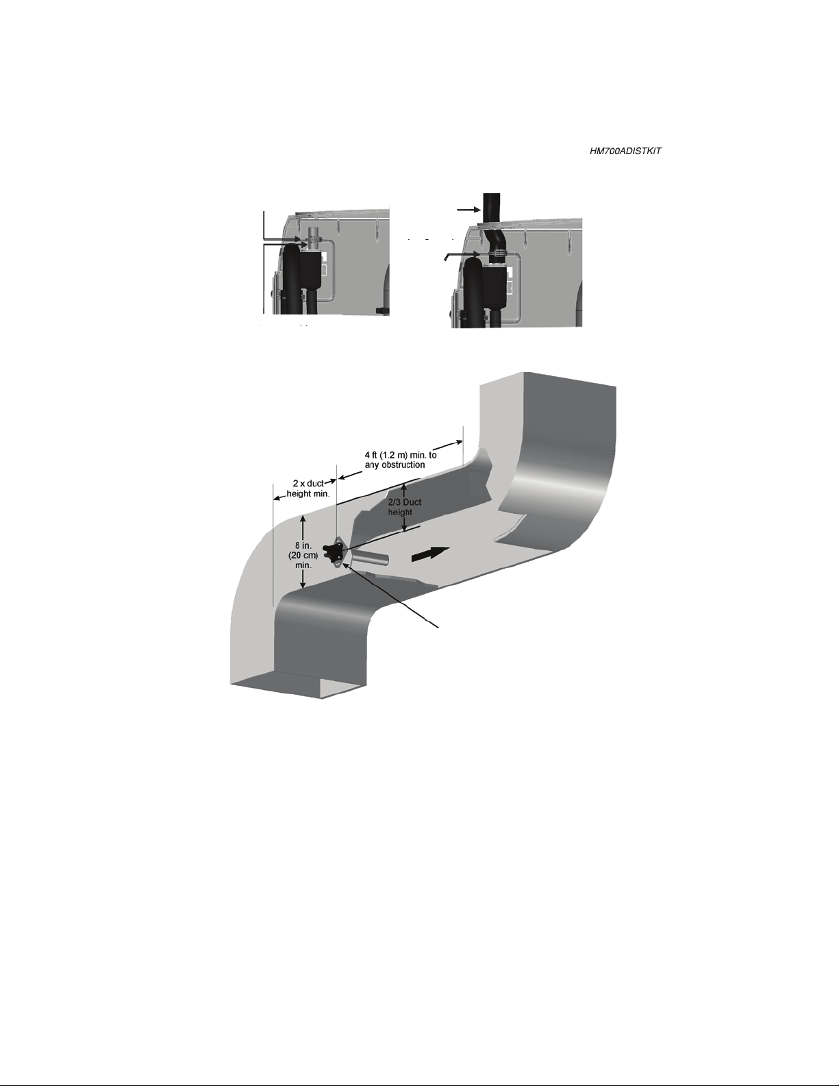
2. Ensure that no condensate produced in the steam
line will remain trapped. Steam naturally flows
upward and condensate naturally flows downward.
3. Ensure steam line properly supported so that no
sags or dips are present.
4. All bends should be done in large radius 12 in.
minimum. Steam hose will soften when and may
kick if too tight a radius is used which can cause a
blockage and excessive back pressure.
5. Horizontal runs of steam must rise 2 in. per foot
(10º) when flow is going upwards away from the
humidifier, or fall 1/2 in. per foot (2º) when flow is
going downwards away from the humidifier.
Condensate Return Guidelines For Main
Steam Lines
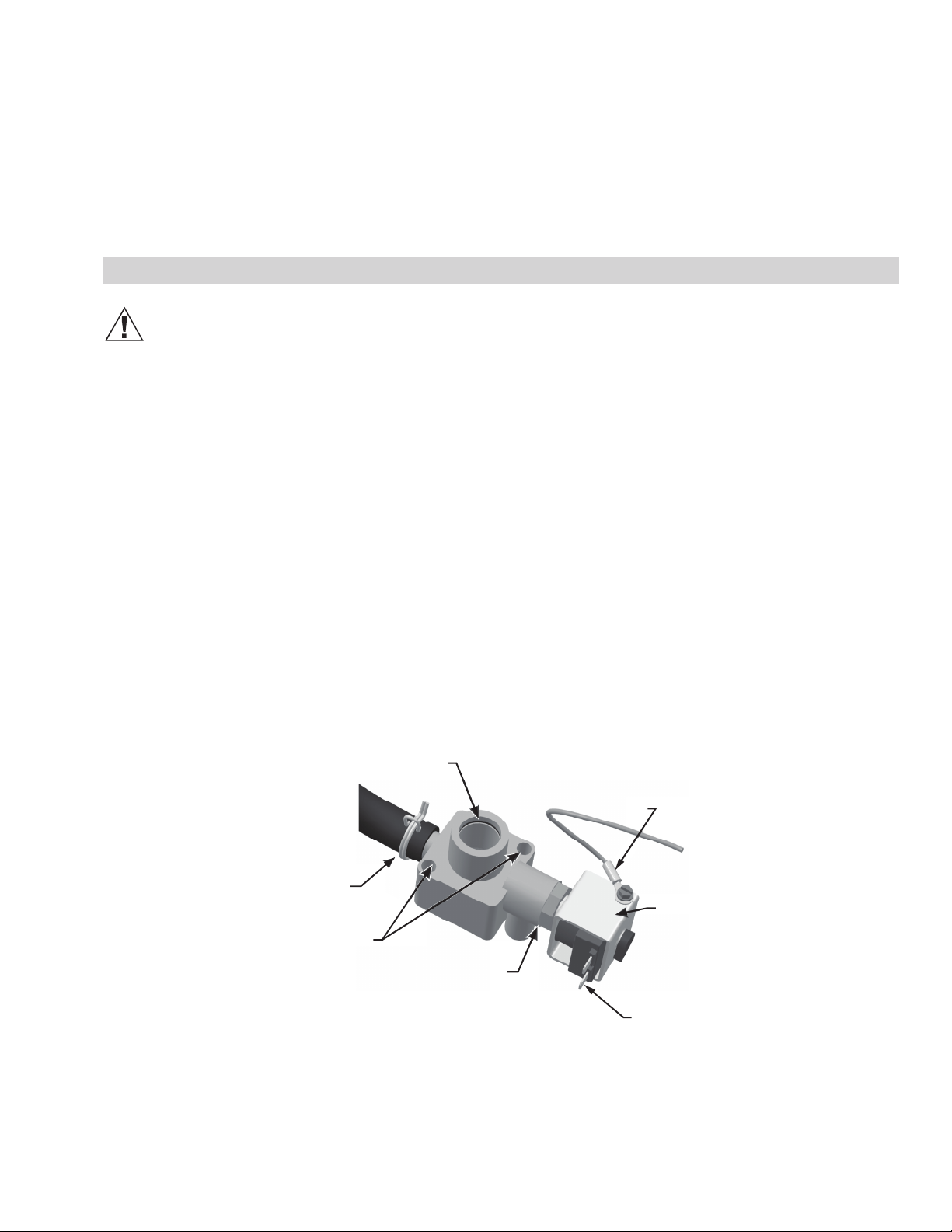
1. Use vertical condensate leg of distributor only. Do
not over-tighten clamp.
2. Condensate traps on steam mains must be located
at all low points in the system, at each elevation
change and or directional change.
3. Horizontal runs of steam must rise 2 in. per foot
(10º) when flow is going upwards away from con-
densate trap, and fall 1/2 in. per foot (2º) when flow
is going downwards towards a condensate trap.
4. In a horizontal run of the steam main, condensate
traps must be located at regular intervals.
5. The condensate trap itself is a section of piping con-
nected to the bottom of the main. A full size tee
must be used to create a condensate trap to allow
the condensate to fall away from the steam flow.
6. Vertical drop of the condensate trap should be
1.5 times the diameter of the steam main but no
less than 12 in.
7. A p-trap should be installed at the bottom of the
condensate trap. The center to center trap height
should be 2 in. greater than duct static pressure
(see Figure 1).
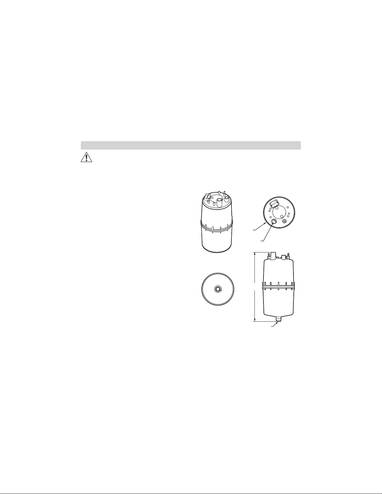
To return condensate for HM700, insert copper tube
(supplied with equipment) half way into the condensate
opening of the fill cup along with the spring clamp
(supplied with equipment).
Insert the condensate hose into the condensate return
hole at the top of the unit, and over the copper tube.
Fasten in place with the spring clamp.
Voltag e
Steam Output Material*
Maximum
Steam Line
Length Possible Losses
Minimum
Airflow CFM
Max Static
Pressurelbs/hr (kg/hr)
Steam
Hose
MED-L
Copper
Tube
Stainless
Steel Tube ft (m) lbs/hr (kg/hr)
110/120V 3.85 (1.75) 7/8 in. 3/4 in. 0.875 x
0.049W
7 (2) 0.5 (0.2) 115 3.0 in. w.c.
220/240V 7.7 (3.5) 12 (3.5) 1.5 (0.7) 230

Fig. 1. Condensate return.
Fig. 2. HM700 Duct Distributor Installation.
1
746-2+'0%14
x3('344)689&)
746-2+
'0%14
-27)68,37)3:)6
'344)689&)%2(
*%78)2; -8,
746-2+'0%14
Mount distributor nozzle to side of duct.

Steam Line Installation Examples
Fig. 3. Steam distributor above humidifier (hose).
Measurements in inches (mm).
Fig. 4. Steam distributor below humidifier (hose).
Measurements in inches (mm).
Fig. 5. Steam distributor below humidifier with
obstruction (hose). Measurements in inches (mm).
Fig. 6. Common steam line installation errors.
Measurements in inches (mm).
1
1-2-191
&)*36)
%2=&)2(
1-2-191
6%(-97 '32()27%8)
0-2)
7944368
&6%'/)87
1-2-191
'322)'8
78)%1
,37)83
'=0-2()6
'32()27%8)
0-2)
1-2-191
1
7944368
&6%'/)87
'32()27%8)
86%4
83(6%-2
1-2-191
6%(-97
1-2-191
&)*36)
%2=&)2(
1
3&7869'8-32
1-2-191
6%(-97
1-2-191
&)*36)
%2=&)2( 7944368
&6%'/)87
,37);-0073*8)23:)68-1)4634)67944368-72)')77%6=
1
23
'32()27%8)
86%4%8
:)68-'%0
86%27-8-32
78)%10-2)
2387034)(
'32()27%8)
86%4238
&)03;
(-786-&9836

INSTALLATION INSTRUCTIONS
Electrode Humidifier Drain Valve
Replacement
HM700ADVALVE
CAUTIO
N
Before Servicing
1. Disconnect main power source before accessing
internal compartments.
2. The plumbing and electrical compartments contain
high voltage components and wiring. Access should
be limited to licensed HVAC professionals only.
3. During and following operation of the humidifier, the
steam components in contact with the steam such
as the cylinder, steam lines, steam distributors, and
condensate lines can become hot and burn if
touched. Please consult HM700 Installation manual
for reference.
4. Installations of humidity equipment installed by
unqualified personnel or the use of non-Honeywell
parts and components will void warranty.
Included in the Box
pDrain Valve
pClip
pPhillips Head Screws
pWiring Harness
pInstallation Instructions
Tools Needed
pScrewdriver
pPliers (optional)
To Replace the Drain Valve
Refer to the humidifier operating manual if necessary.
1. Drain cylinder.
2. Turn off the unit when the cylinder is empty.
3. Disconnect power to the unit.
4. Remove cylinder.
5. Disconnect spade terminals from the drain valve.
6. Remove the two screws holding the valve to the drain
pan.
7. Squeeze the tabs of the spring clamp holding the hose
to the drain valve and slide it up the hose. Pull hose
from drain valve.
8. Drain valve can be removed and replaced with new one.
9. Reverse steps above to install drain valve.
NOTE: New screws and hose clamp provided.
Fig. 1. Drain valve.
'=0-2()64368
%2(36-2+
+6392(
;-6)
730)23-(
74%()
'322)'8367
&6%77298
%'89%836
7'6);7
,37)%2(
,37)'0%14
1

INSTALLATION INSTRUCTIONS
Electrode Humidifier Fill Valve
Replacement
HM700AFVALVE
CAUTION
Before Servicing
1. Disconnect main power source before
accessing internal compartments.
2. The plumbing and electrical compartments
contain high voltage components and wiring.
Access should be limited to licensed HVAC
professionals only.
3. During and following operation of the
humidifier, the steam components in contact
with the steam such as the cylinder, steam
lines, steam distributors, and condensate lines
can become hot and burn if touched.
4. Installations of humidity equipment installed by
unqualified personnel or the use of non-
Honeywell parts and components will void
warranty.
Included in the Box
pFill Valve
pTie Wrap
pClip
pPhillips Head Screws
pInstallation Instructions
Tools Needed
pScrewdriver
pPliers
Step 1
Refer to the humidifier operating manual if necessary.
1. Shut off water supply to the unit.
2. Disconnect power to unit.
3. Locate Fill Valve.
4. If necessary, remove cylinder.
Step 2
Removing old Fill Valve
1. Disconnect the wiring to the solenoid.
2. Using pliers, slide the spring clamp up the hose.
3. Disconnect the hose from the fill valve.
CAUTION
The remaining water located in the hose will
spill out.
Have something on hand to absorb the water.
Fig. 1. Disconnecting old fill valve.
Step 3
1. On the opposite side of the wall where the valve is
mounted, unscrew the fitting from the fill valve, and
remove screws.
Fig. 2. Removing old fill valve.
1
;-6)
8)61-2%07
:%0:),3 7 )
746-2+'0%14
1
6)13:)
*-88-2+
6)13:)
7'6);7

ELECTRODE HUMIDIFIER FILL VALVE REPLACEMENT
Step 4
Installing new Fill Valve
1. If necessary, reposition valvems metal bracket by
sliding it out. By pulling the solenoid out of the
valve, you may orient the terminals in a more con-
venient direction.
2. Place new Fill Valve into port.
3. Use provided machine screws (replacing those
removed in Step 3) to fasten the valve onto the wall
of the unit.
4. Screw fitting back onto valve.
Step 5
1. Place spring clamp (provided) onto hose.
2. Slide hose onto valve, then slide spring clamp
around valve nozzle. Ensure that the clamp is tight
around the valve to avoid leaks.
3. Reconnect wires to solenoid.
Step 6
1. Restart unit. Observe components and connec-
tions for leaks.
Table of contents
Other Klimaire Humidifier manuals