KLING & FREITAG LINE 212-6-SP User manual

Self Powered LINE 212-6 - SP / LINE 212-9 - SP
Benutzer Handbuch
Wichtige Informationen,
vor Inbetriebnahme lesen!
KLING &FREITAG GmbH
Junkersstrasse 14
D-30179 Hannover
TEL 0 (049) 511- 969 97-0
FAX 0 (049) 511- 67 37 94
www.kling-freitag.de
User's Manual
Important Information,
Please Read Before Use!
KLING &FREITAG GmbH
Junkersstrasse 14
D-30179 Hannover
PHONE 0 (049) 511- 969 97-0
FAX 0 (049) 511- 67 37 94
www.kling-freitag.de
Version 4.1
Released: 23.03.2006

User’s Manual LINE 212-6 - SP / LINE 212-9 - SP
KLING & FREITAG GMBH ©2003 - 2006 Version 4.1, 19.06.2006 Page 2 of 45

User’s Manual LINE 212-6 - SP / LINE 212-9 - SP
KLING & FREITAG GMBH ©2003 - 2006 Version 4.1, 19.06.2006 Page 3 of 45
Thank you for your decision to buy a Kling & Freitag sound system. To guarantee a
trouble-free operating of the equipment and to allow the KLING & FREITAG --- ‘SP’
speaker system to achieve its full potential please read the operating instructions care-
fully before use.
With the purchase of a LINE 212 --- SP system with integrated power amplifier tech-
nology, you have acquired a speaker system with the highest possible quality and
performance capabilities.
As the owner of this system, you now have a versatile and highly professional tool
which, when operated properly, is a true pleasure to use.
Symbols in User's Manual
Warning
This symbol indicates the possibility of life-threatening danger and a
health risk for persons. Not following these instructions may result in
serious health problems including potentially fatal injuries.
Caution
This symbol indicates a possibly dangerous situation. Not following
these instructions may cause minor injuries or cause property damage.
Important
This symbol gives instructions for the proper use of the described prod-
ucts. Not following these instructions may cause malfunctions or prop-
erty damage.
Information about this User's Manual
User's Manual K&F LINE 212-6 - SP / LINE 212-9 - SP, Version 4.1, 23.03.2006
© by André Figula, Kling & Freitag GmbH, May 2003 - 2006; all rights reserved.
All specifications in this manual are based on information available at the time of pub-
lishing for the features and safety guidelines of the described products.
Technical specifications, measurements, weights and properties are not guaranteed.
The manufacturer reserves the right to make product alterations within legal provisions
as well as changes to improve product quality.
All persons who use the speaker system must have this guide and all further
information for safe operations available to them during assembly, disassem-
bly, and use.
We appreciate any input with suggestions and improvements for this manual.
Please send this to us at the following address:
KLING & FREITAG GMBH, Junkersstr.14, D-30179 Hannover
Phone +49 (0) 511 - 96 99 70, Fax +49 (0) 511 - 67 37 94

User’s Manual LINE 212-6 - SP / LINE 212-9 - SP
KLING & FREITAG GMBH ©2003 - 2006 Version 4.1, 19.06.2006 Page 4 of 45
Contents
Chapter Page
1. General Safety Instructions 5
2. Introduction SP Loudspeakers 7
3. Connectors, Controls und Displays 9
4. Power Cord 13
5. Rigging Instructions for Line 212 Systems 14
5.1 Vertical Suspension 14
5.2 Horizontal Suspension 15
6. Using the ‘allsafe JUNGFALK’ Flying Points 16
7. Using the Rear Mounted ‘allsafe JUNGFALK’ Flying Track 17
7.1 Mounting the Single Stud Fittings 17
7.2 Mounting the Double Stud Fitting 18
8. Coverage Pattern of the Line 212 --- SP Systems 19
8.1 Changing the Coverage Pattern 19
9. Mounting Instructions for Speakers 20
9.1 Proper Arrangement of the Loudspeakers 20
9.2 Arrayed Speaker Systems (Cluster) 21
9.3 LINE 212 Systems on Top of SW 215E 22
10. Wiring 23
10.1 Avoiding Ground Loops 23
10.1.1 What is a Ground Loop? 23
10.1.2 Avoiding Ground Loops 23
10.2 Connecting the Power Connectors to the Connecting Terminal 24
11. Configurations and Connecting Diagrams 25
11.1 Operating the Systems without C2 Controller 25
11.1.1 Full-Range Mode 25
11.1.2 Full Range Mode with Subwoofer 26
11.2 Operating the Systems with C2 Controller 27
11.2.1 Full-Range Mode with K&F C2 Controller 27
11.2.2 2-Way Active Mode with K&F Controller C2 28
11.3 Maximum Configuration 29
12. Operating the Speakers 30
13. Touching Up Damage to Paint / Changing the Front Foam 30
14. Block Diagram LINE 212 - SP 31
15. Technical Specifications 32
15.1 LINE 212-6 - SP 32
15.2 LINE 212-9 - SP 33
16. Measuring Charts 34
16.1 LINE 212-6 - SP 34
16.2 LINE 212-9 - SP 36
17. Dimensions 38
18. Accessories for the LINE 212 System 39
19. Regulations for Disposal 40
19.1 Germany: 40
19.2 EU, Norway, Island, and Liechtenstein (not Germany): 40
19.3 Other countries 40
20. Declaration of Conformity and International Certificates 41
20.1 Declaration of Conformity 41
20.2 EMV Certificate Directive 89 / 336 / EWG 42
20.3 TÜV Certificate for the USA and Canada (UL 6500) 44
21. Included Safety and Mounting Instructions for Loudspeakers and Accessories

User’s Manual LINE 212-6 - SP / LINE 212-9 - SP
KLING & FREITAG GMBH ©2003 - 2006 Version 4.1, 19.06.2006 Page 5 of 45
1. General Safety Instructions
Warning: To avoid electric shock hazard, do not expose this
appliance to rain or moisture. The enclosures may only be
opened by qualified personnel!
Do not install devices in any of the following places:
−where the devices are permanently exposed to direct sunlight.
−near any heat sources and open fire. Do not put candles etc. on top of the speaker.
−where the airflow for cooling is blocked. A minimum distance of 10 cm to the heat
sink on the rear of the speaker must be kept.
−where the devices are exposed to high moisture. Objects filled with liquids, such as
a vase, must not be placed on the speaker.
−where the devices are exposed to strong vibrations and dust.
Power supply
Before connecting the AC power cable of the SP speaker, please check if the available
voltage is compatible with the operating voltage as indicated on the unit. If this is not
the case, then the unit needs to be adapted by the manufacturer or an authorized ser-
vice centre. If the unit is not compatible with the available voltage, it should never be
connected! This could irreparably ruin the SP speaker.
Make sure that the power outlet supplies a ground connector, which must be con-
nected to the unit via the PE conductor of the power cord!
All equipment, which is connected together using signal cables and has a connection to
protective earth, must be connected to a common PE conductor. If not, there is a risk of
an electric shock or the destruction of the connected equipment.
The power plug must always be used to disconnect from the power supply. Further-
more, the power plug must be easily accessible for use at all times.
Protection of electrical cables
Power cords should be laid in such a way that they are protected against footstep dam-
ages, tensile strain and against being trapped.
Transportation
When transporting the equipment, make sure that it is protected from vibrations.
Cleaning
The equipment should only be cleaned with a damp cloth when it is not plugged in.
Pauses in use
The power cord should be disconnected from the power source during longer pauses in
use.
Intrusion of objects or liquids
No objects or liquids should intrude or leak into the equipment.
Warning
Risk of electric shock!
Do not open the units!
CAUTION

User’s Manual LINE 212-6 - SP / LINE 212-9 - SP
KLING & FREITAG GMBH ©2003 - 2006 Version 4.1, 19.06.2006 Page 6 of 45
Maintenance and technical service
The user should not perform any maintenance work on the equipment other than that
which is described in this manual. Repairs should be executed by a qualified service
technician only.
In the following cases, the unit should be serviced by an authorized technician only if:
−the power cord or the mains connectors have been damaged.
−objects or liquids have gotten into it.
−it was exposed to rain.
−it doesn't appear to be functioning properly.
−it has fallen down or the enclosure is damaged.
Mounting the speakers
If the weight of the speaker exceeds 25 kg then it is necessary for two people to carry it.
To prevent injury, this equipment must be securely placed on the floor or secured to the
wall according to the mounting instructions. Speakers, which are stacked, must be se-
cured with securing straps. Please note that speakers can move as a result of vibrations.
To prevent them from falling from their mounted position, they must be secured prop-
erly.
Speakers may only be suspended by qualified personnel.
Never use signal cables or power cords for suspending, aligning or securing the systems.
When laying the connecting cables, make sure that nobody can trip.
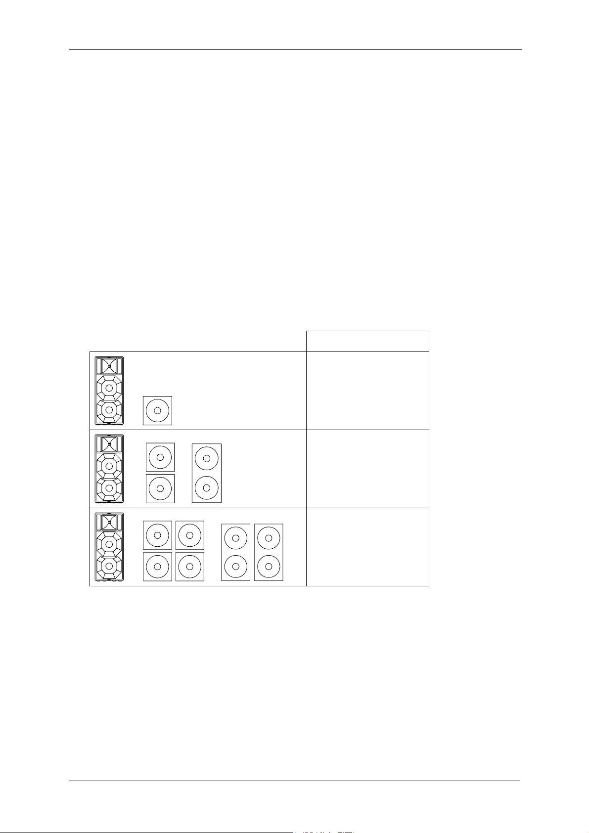
The speakers must be hung by using at least two of the designated flying points. The
same applies when lifting and aligning the speakers.
Never hang more than two speakers under one another without using the designated
Kling & Freitag rigging equipment.
Ensure that all installation connections comply with the applicable safety guidelines and
that the size and strength are sufficient. Further instructions are in our user's manual for
assembly equipment and in the general safety instructions for speakers and assembly
equipment.
For mobile and fixed installations, use only rigging equipment from KLING & FREITAG.
Make sure to observe the included safety and mounting instructions for loudspeakers
and accessories.
Unwanted interference
RF interference on the power cord or on the line signal cables may lead to unwanted
sound interference.
Damage caused by the speakers' magnetic fields
Speakers are permanently surrounded by a magnetic field, even when they are not op-
erating. Therefore, during transport and placement of the speakers, it is important to
ensure that there is always approx. 1 m between the speakers and magnetic data media
and computer/video monitors.
The following signals may damage the speakers
−permanent high-pitched signals with high frequency and continuous noise from
feedback.
−permanently distorted signals with high power.
−noises, which occur when the SP speaker is connected while equipment is being
connected, disconnected or switched on.
Preventing hearing damage
To prevent the risk of hearing damage, avoid being too close to operating speakers,
even if the volume level seems to be low enough. In general, volume levels over 90 dB
can cause hearing damage.
Warning
Important
Caution

User’s Manual LINE 212-6 - SP / LINE 212-9 - SP
KLING & FREITAG GMBH ©2003 - 2006 Version 4.1, 19.06.2006 Page 7 of 45
2. Introduction SP Loudspeakers
‘SP’ denotes ‘Self Powered’ series in the K&F range of loudspeakers. Based on selected
K&F speaker systems, the ‘SP’ models are equipped with state-of-the-art integrated
driver circuits and Class D power amplifier technology. The extremely lightweight
system electronics replace ponderous racks, power amplifiers, controllers, and speaker
cables.
Aside from the integrated power amplifier and input modules with controller func-
tions, the full-range systems possess a passive crossover so that the advantageous
features provided by the K&F passive technology (all-pass filter, protection circuits)
remain usable. The frequency separation for the subwoofers is controlled by an active
110 Hz low-pass filter.
Integrated phase optimisation allows for all systems in the ‘SP Series’ to be combin-
able with one another. With this, the ‘SP’ speakers, when the filter section is switched
off, have a completely comparable sound to the corresponding versions without inte-
grated power amplifier technology. Operations using the K&F C2 Controller are also
possible, which is, for example, appropriate for combined applications with equivalent
passive systems or for the use of C2 presets (clustering = Top Low Cut, Bass-Boost
etc.).
Operating the ‘SP Series’ is incredibly easy: The full-range systems reproduce the com-
plete frequency spectrum. If necessary, the ‘SP’ subwoofers in parallel operations can
provide an additional bass boost.
The Input Module
−Line signal input
−Limiter section (feed-forward RMS-limiter and peak limiter in feed-back design).
−High pass filter, 45 Hz tops, and 32 Hz subwoofers
−Low pass filter 110 Hz (only subwoofer systems)
−System specific, switchable frequency deemphasis (‘FILTERS ON/ OFF’) controllable
by a covered switch on the connecting terminal
−Phase correction
−Level adjustment (countersunk level control on the connecting terminal)
The Amplifier Module
−1 x, or 2 x 1 kW Class D state-of-the-art power amplifier
−Minimal dimensions (speaker dimensions of the models without the ‘SP’ module are
retained)
−Low weight (weight increase of 2.5 / 4 kg as compared to systems without the ‘SP’
module; and with the Line 212 --- SP, the weight even stays identical)
−High efficiency enables convection cooling, because of which bothersome fans are
unnecessary
−High fidelity (even in high frequency range) and a large power bandwidth resulting
from impedance optimisation

User’s Manual LINE 212-6 - SP / LINE 212-9 - SP
KLING & FREITAG GMBH ©2003 - 2006 Version 4.1, 19.06.2006 Page 8 of 45
Modes of Operation
−Operations without external controller:
with activated filters (FILTERS ‘ON’), all K&F models in the ‘SP Series’ are combin-
able with one another by simply linking the signal from one speaker to the next.
−With optional K&F system controller*:
with system plug-in cards via the K&F Controller C2 or an Audio DSP*
−if used with BSS Soundweb, FDS 366, 336, 334, and XTA DP 226, 224, K&F sys-
tem parameters are available upon request
* The operation of the K&F ‘SP’ models with Controller C2 or Audio DSP is recom-
mended for uses in which special filter presets are advisable, i.e. in combination with
passive systems of the ‘CA Series’, in cluster operations (top low cut), when bass and
high boost are necessary, adjustment to the room acoustics (EQ), etc.
The following K&F ‘SP’ speakers are available:
Full-range systems: CA 1001 - SP,
CA 1201 - SP,
CA1215-6 - SP, CA 1215-9 - SP
CA 1515-6 - SP, CA 1515-9 - SP
LINE 212-6 - SP, LINE 212-9 --- SP
Subwoofers: SW 112 - SP, SWi 112 - SP,
SW 115E - SP, SWi 115E - SP,
SW 118E - SP, SWi 118E - SP,
SW 215E - SP

User’s Manual LINE 212-6 - SP / LINE 212-9 - SP
KLING & FREITAG GMBH ©2003 - 2006 Version 4.1, 19.06.2006 Page 9 of 45
3. Connectors, Controls und Displays
2
8
6
5
7
3
4
1
1) LINE IN and LINE OUT (+6 dB)
Electronically balanced input and output connectors. Use the XLR female connector
(marked ‘IN’) as input. The parallel-wired XLR male connector (‘OUT’) is for connec-
tion to further ‘SP’ loudspeakers.
2) GROUND LIFT
When the ‘Ground Lift’ switch is set to LIFT, pin 1 of the LINE IN connector (ground)
is not connected to the chassis ground of the integrated amplifier module. The
ground connection between LINE IN (XLR male) and LINE OUT (XLR female) is main-
tained. The use of the ‘Ground Lift’ switch is sometimes necessary in dealing with
hum problems (see chapter 10.1 )
Never
NeverNever
Never tape over the protective earth on the plug
tape over the protective earth on the plugtape over the protective earth on the plug
tape over the protective earth on the plug ---
------
--- danger to life!
danger to life!danger to life!
danger to life!
3) PROTECTIVE COVER
The protective cover prevents unwanted adjustment of the gain control and filter
ON / OFF switch. The cover has a snap-in lock. In order to reach the controls be-
neath, turn the cover sharply in the direction of the arrow.
Warning

User’s Manual LINE 212-6 - SP / LINE 212-9 - SP
KLING & FREITAG GMBH ©2003 - 2006 Version 4.1, 19.06.2006 Page 10 of 45
4) GAIN CONTROL (± 6 dB)
a) The gain control can be used to adjust the input level of the amplifier module
by ± 6dB. It serves to balance the volume levels of the various systems. In or-
der to avoid overloading the input circuit or mixer’s output circuit, it should
normally be set in the case of K&F full-range systems at 0 dB (centre notch
setting).
b) When operating with C2 Controller, set the input level of the amplifier mod-
ule on the C2 Controller (Input Gain). The gain control on the SP speaker
should be set at 0 dB (centre notch setting). One exception to this rule is a
cluster arrangement, in which the inner speakers should be set at a lower
level than the outer ones. In this case, the level of the gain control on the in-
ner SP speakers can be adjusted downwards accordingly.
When operating with additional bass systems it is very important that the respec-
tive volume levels between the top speakers and the bass systems are correctly
balanced. To this end, the sound engineer should check the volume levels during
the set-up and adjust them accordingly. When setting up a system without C2
Controller this adjustment should be carried out using the gain control of the SP
subwoofer; in the case of a system with C2 Controller, use the 'Sub Gain' control
on the C2 Controller.
Normally we recommend the following settings*
Configuration:
Configuration:Configuration:
Configuration: Gain control
Gain controlGain control
Gain control
+
Line 212:
-
--
- 6 dB
6 dB6 dB
6 dB
Subwoofer / C2 Sub-Gain:
+6 dB
+6 dB+6 dB
+6 dB
+
or
Line 212:
0 dB
0 dB0 dB
0 dB
Subwoofer / C2 Sub-Gain:
+6 dB
+6 dB+6 dB
+6 dB
+
or
Line 212:
0 dB
0 dB0 dB
0 dB
Subwoofer / C2 Sub-Gain:
0 dB
0 dB0 dB
0 dB
* These details may vary due to different room geometries. The position of a bass
speaker is also crucial for its actual sound level. A bass speaker, which is on the
floor, can be a few decibels louder than a flown bass system because of the floor
reflections. Because of this, a sound engineer must always fine-tune the system us-
ing the corresponding level controls.

User’s Manual LINE 212-6 - SP / LINE 212-9 - SP
KLING & FREITAG GMBH ©2003 - 2006 Version 4.1, 19.06.2006 Page 11 of 45
5) FILTERS ON / OFF (High Pass / Low Pass / Equalizer)
This switch turns the filter in the SP module on (‘ON’), or off (‘OFF’).
a) The switch should always be in the ‘ON’ position when the speakers are being
driven without C2 Controller.
b) The switch should always be in the ‘OFF’ position when the speakers are being
driven with C2 Controller.
The filters consist of:
−high-pass: protects the speakers against mechanical stress due to frequen-
cies outside the speaker's frequency range (protection against subsonic fre-
quencies)
−EQ: filter for basic equalization, optimising the frequency response of the
speaker systems.
Furthermore, the SP filter module has a phase alignment, which prevents loss
of certain frequencies due to phase shift between mid-high and bass systems.
Thus the combination of all available K&F mid-high SP systems with all K&F
bass SP systems is possible, and 100% phase compatibility with all K&F speak-
ers operating in conjunction with the K&F C2 Controller in the ‘2-way active’
mode is guaranteed.
6) LED POWER ON (GREEN) and LIMIT / PROTECT (RED)
The LED is dual-purpose:
a) When the LED is green, the speaker is connected to the supply voltage and
ready for operation
b) The LED will turn red if…
…the input signal is so high that the internal limiters reduce its level.
The limiters consist of a peak limiter, which limits the peaks of the signal,
and an RMS / thermal limiter, which continuously regulates excessive levels.
During normal operation, the red light may occasionally illuminate briefly
when the barely audible limiter cuts in to limit peak levels. It does indicate
that the level peaks are limited by the limiter circuit. The peak performance
of the speaker has then been reached.
Should the red light come on more frequently or remain illuminated, the
output level of the mixer should be reduced. When speakers with and
without SP module are in operation simultaneously, the gain control on the
SP speaker can be turned down, provided the level is sufficient for the
other power amplifiers. The limiter protects the speaker from damage due
to excessive levels.

User’s Manual LINE 212-6 - SP / LINE 212-9 - SP
KLING & FREITAG GMBH ©2003 - 2006 Version 4.1, 19.06.2006 Page 12 of 45
c) The LED stays permanently red, if…
…the protection circuitry of the integrated power amplifier cuts in and as a
result, no further signal reaches the speaker (Protect Mode).
The protection circuitry switches off the integrated power amplifier,…
−…if the temperature of the amplifier module is too high. As soon as
the temperature falls below the critical value, the amplifier module is
switched on again automatically. Excessive temperatures can be
caused for example by inadequate ventilation of the heat sink. Make
sure that the heat sinks are not covered or positioned directly against a
wall.
−…if the output impedance is too low or in the case of a short circuit,
caused for example by a defective chassis or a faulty component on
the crossover.
−…if the amplifier has an internal fault. The SP amplifier module checks
that all is functioning correctly during operation. As soon as a fault be-
comes apparent, the module switches into protect mode. If only one
module has a fault, the input signal is attenuated by 70 dB, to prevent
damage to the other module.
Measures to be taken when LED is red:
Fault Measure Function
LED remains red or flickers
continually during opera-
tion.
Reduce output level on mixer until the
LED goes out or flickers only occasion-
ally
Limiter
No output signal, LED
shows red in spite of re-
duced mixer level.
Allow to cool. The amplifier module
switches itself on after a few minutes.
Provide sufficient ventilation.
Temperature
protection
No output signal, LED stays
red after cooling down.
Have loudspeaker checked by
authorized service technician.
Other pro-
tection
Output signal is too low, no
bass frequencies or no high
frequencies.
Have loudspeaker checked by
authorized service technician.
Other pro-
tection
7) AC MAINS ‘IN’
Connect this PowerCon socket using the mains cable supplied to a max. 16 A fused
mains socket, paying particular attention to the stated mains voltage! Connection
to an incorrect mains voltage can result in irreparable damage!
8) AC MAINS ‘OUT’
Socket for connection to further equipment such as further speakers with SP mod-
ule. Use only connection cables, which conform to your national safety regul
Use only connection cables, which conform to your national safety regulUse only connection cables, which conform to your national safety regul
Use only connection cables, which conform to your national safety regula-
a-a-
a-
tions.
tions.tions.
tions.
Maximum power consumption: 230 V: 10 A / 2300 W
110 V: 10 A / 1150 W
Important
Warning

User’s Manual LINE 212-6 - SP / LINE 212-9 - SP
KLING & FREITAG GMBH ©2003 - 2006 Version 4.1, 19.06.2006 Page 13 of 45
4. Power Cord
In Germany, a pre-constructed ready for use power cord is included in the delivery.
For deliveries to foreign countries, a pre-constructed power cord incl. PowerCon plug is
included. Because of the different standards abroad, the power plug is not included.
This must be subsequently assembled only by qualified electrical specialists.
brown = BN = L
green / yellow = GNYE =
blue = BU = N

User’s Manual LINE 212-6 - SP / LINE 212-9 - SP
KLING & FREITAG GMBH ©2003 - 2006 Version 4.1, 19.06.2006 Page 14 of 45
5. Rigging Instructions for Line 212 Systems
The speakers may only be mounted by trained specialised pe
The speakers may only be mounted by trained specialised peThe speakers may only be mounted by trained specialised pe
The speakers may only be mounted by trained specialised per
rr
rsonnel with proof
sonnel with proofsonnel with proof
sonnel with proof
of their qualifications as an experienced ‘rigger’.
of their qualifications as an experienced ‘rigger’.of their qualifications as an experienced ‘rigger’.
of their qualifications as an experienced ‘rigger’.
Please follow the accompanying instructions for speakers and assem
Please follow the accompanying instructions for speakers and assemPlease follow the accompanying instructions for speakers and assem
Please follow the accompanying instructions for speakers and assembly equipment.
bly equipment.bly equipment.
bly equipment.
Ensure that all connections are secured to prevent their detaching on their own and that
only admissible statically tested and sufficiently sized connecting devices, ropes and
chains are used.
Pay attention to the required safety factors. Please follow the accompanying safety and
mounting instructions carefully.
A maximum load of 73 kg may be suspended from the two flying points of one Line
212 system. This means a maximum additional load of 36.5 kg on each
This means a maximum additional load of 36.5 kg on eachThis means a maximum additional load of 36.5 kg on each
This means a maximum additional load of 36.5 kg on each ‘allsafe
JUNGFALK’ flying point.
flying point.flying point.
flying point. This applies for both vertical (see details on this page) and
horizontal suspension (see details on next page).
5.1 Vertical Suspension
The Line 212 System must always be mounted
with two wire ropes or chains, which are inde-
pendent of one another! Furthermore, the sys-
tems, no matter if individual or connected to
one another, must be secured onto the ‘allsafe
JUNGFALK’ flying track on the rear. This safety
rope may be used for aligning the systems.
The safety rope must have a minimum length
The safety rope must have a minimum lengthThe safety rope must have a minimum length
The safety rope must have a minimum length
of 100 cm and must be
of 100 cm and must beof 100 cm and must be
of 100 cm and must be attached so that, in
attached so that, inattached so that, in
attached so that, in
case it falls, the height of the fall is kept to a
case it falls, the height of the fall is kept to acase it falls, the height of the fall is kept to a
case it falls, the height of the fall is kept to a
minimum. A possible fall height of 20 cm may
minimum. A possible fall height of 20 cm mayminimum. A possible fall height of 20 cm may
minimum. A possible fall height of 20 cm may
not be exceeded! With a higher fall height,
not be exceeded! With a higher fall height,not be exceeded! With a higher fall height,
not be exceeded! With a higher fall height,
the dynamic load of a fall could be inadmi
the dynamic load of a fall could be inadmithe dynamic load of a fall could be inadmi
the dynamic load of a fall could be inadmis-
s-s-
s-
sibly high; potential risk of system crash.
sibly high; potential risk of system crash.sibly high; potential risk of system crash.
sibly high; potential risk of system crash.
The safety ropes of different systems must al-
ways come together at one point.
Each of the utilised separate lifting accessories
(chains / wires / shackles) must be able to carry
the 12-fold load of the total weight.
While installing, be sure that the system can
swing in case a rigging point fails. With this in
mind, the speaker must be mounted so that no
people or objects are within the potential range
of the swinging speakers.
The weight of the speaker hung below may not
exceed 73 kg (this weight corresponds to the
approx. weight of a SW 215E-SP).
The angle of the rope / chain to the top of the
speaker mounted below may not exceed 45°.
Warning

User’s Manual LINE 212-6 - SP / LINE 212-9 - SP
KLING & FREITAG GMBH ©2003 - 2006 Version 4.1, 19.06.2006 Page 15 of 45
5.2 Horizontal Suspension
If a speaker unit consisting of several connected systems is to be
flown and aligned, then the individual speakers must be attached
to one another before connecting them to the ‘allsafe JUNGFALK’
Flying Track. Consult the provided illustration when doing so. For
the rear connection of the loudspeaker systems, use the double
stud fittings available from Kling & Freitag and a proven 1/2"
shackle (alternative single stud fittings and 3/8" shackle). Pull the
threaded bolt of the shackle with a torque of 10 Nm (hand
(hand(hand
(hand-
--
-tight
tighttight
tight
with 200 mm long lever, e.g. screwdriver).
with 200 mm long lever, e.g. screwdriver).with 200 mm long lever, e.g. screwdriver).
with 200 mm long lever, e.g. screwdriver).
Alternatively, you
Alternatively, youAlternatively, you
Alternatively, you
can use prov
can use provcan use prov
can use proven, high
en, highen, high
en, high-
--
-strength shackles with a cotter pin
strength shackles with a cotter pinstrength shackles with a cotter pin
strength shackles with a cotter pin.
..
. Only
in this way can you ensure that the bolt will not become loose.
The ‘allsafe JUNGFALK’ flying track can only support weights up
to 73 kg. Therefore, the load must be distributed on several flying tracks when suspend-
ing the systems.
For horizontal operations, the system is designed for a maximum array of three Line
212-6 systems. More of theses systems may not be flown below one another.
We recommend using the BGV C1 certified and type tested Click & Fly Rigging
System for mounting the Line 212 systems (see the ‘Click & Fly for Line 212 /
SW215E' user's manual).
Please follow the following instructions for flown operations without the Click
& Fly Rigging System:
Wrong:
−The upper rigging points of the top speaker
must carry the full load. Consequently, the
permissible max. load of the top points is ex-
ceeded.
−The speakers are not secured by the additional
safeties.
Right:
−The load of the individual speakers is threaded
through the bent continuous bracket. The load
is, therefore, held by the bracket and the
speakers’ flying points consequently only have
to carry the load of the corresponding speaker.
−The speakers are connected to one another on
the rear. The suspension point is located on the
connection of the two lower speakers. As a re-
sult, the load is distributed to both speakers.
Warning

User’s Manual LINE 212-6 - SP / LINE 212-9 - SP
KLING & FREITAG GMBH ©2003 - 2006 Version 4.1, 19.06.2006 Page 16 of 45
6. Using the ‘allsafe JUNGFALK’ Flying Points
Single Stud Fitting
Used as fastener to the ‘allsafe
JUNGFALK’ Flying Point.
‘allsafe JUNGFALK’ Flying Point
Receptacle for special fasteners.
1.)
2.)
Take the single stud fitting in one
hand...
... and push the locking device up
against the spring tension.
3.)
4.)
Put the flat head of the holding
bolt into the guiding of the flying
point.
Release the locking device when
the single stud fitting is located in
the middle of the flying point.
Make sure that the locking device
clicks into place.
5.)
Check that the single stud fitting is
securely fastened and cannot be
pulled out.
Warning

User’s Manual LINE 212-6 - SP / LINE 212-9 - SP
KLING & FREITAG GMBH ©2003 - 2006 Version 4.1, 19.06.2006 Page 17 of 45
7. Using the Rear Mounted ‘allsafe JUNGFALK’ Flying Track
The ‘allsafe JUNGFALK’ flying track can be used for fixing and adjust-
ing the speaker systems.
The ‘allsafe JUNGFALK’ flying track can only support weights
up to 73 kg!
Please also consult the provided instructions for speakers and
assembly equipment.
7.1 Mounting the Single Stud Fittings
Single Stud Fitting
Used as fastener to the ‘allsafe
JUNGFALK’ Flying Point and the
‘allsafe JUNGFALK’ Flying Track.
‘allsafe JUNGFALK’ Flying Track
Receptacle for special fasteners such
as the single stud fitting.
1.)
2.)
Take the single stud fitting in one
hand...
... and push the locking device up
against the spring tension.
3.)
4.)
Slide the flat head of the holding
bolt into the guiding device of
the flying track and slide the sin-
gle stud fitting sideways into the
flying track.
Release the locking device when the
single stud fitting is located over the
tabs of the track. Make sure that the
locking device clicks into place. Make
sure that it is secured tightly.
Warning
Warning

User’s Manual LINE 212-6 - SP / LINE 212-9 - SP
KLING & FREITAG GMBH ©2003 - 2006 Version 4.1, 19.06.2006 Page 18 of 45
7.2 Mounting the Double Stud Fitting
Double Stud Fitting
Used as fastener to the ‘allsafe
JUNGFALK’ Flying Point and the
‘allsafe JUNGFALK’ Flying Track.
‘allsafe JUNGFALK’ Flying Track
Receptacle for the double stud fit-
ting.
1.)
2.)
Align the double stud fitting as
shown above and push it into the
track,…
... slide the pushed double stud fitting
to the middle of the speaker until it
clicks into place. Make sure that it is
secured tightly.
Warning

User’s Manual LINE 212-6 - SP / LINE 212-9 - SP
KLING & FREITAG GMBH ©2003 - 2006 Version 4.1, 19.06.2006 Page 19 of 45
8. Coverage Pattern of the Line 212 --- SP Systems
The Line 212 can be operated in a vertical or horizontal position. The coverage pattern
of the speaker can be adapted to special needs by a 90° rotatable horn.
The following graphics demonstrate how to recognize how the built-in horn emits in a
standing speaker: To determine the coverage pattern of the high frequency horn,
shine a flashlight through the front covering at the level of the horn. You will find a
silver stripe that determines the position and coverage angles of the horn.
DEFINITION:
DEFINITION:DEFINITION:
DEFINITION:
Standing speaker:
Model
ModelModel
Model
Horn not rotated
Horn not rotatedHorn not rotated
Horn not rotated
Horn rotated
Horn rotatedHorn rotated
Horn rotated
LINE 212-6 - SP 65° h x 50° v 50° h x 65° v
LINE 212-9 - SP 90° h x 50° v 50° h x 90° v
8.1 Changing the Coverage Pattern
The front grille of the Line 212 - SP is divided into two sections (except the version ‘Out-
door Installation’). Changing the coverage angle is possible by only removing the upper
section of the grille. To turn the horn, follow these steps:
1) Disconnect the power plug!
2) Make sure that no objects fall into the enclosure!
3) Remove the four grille mounting screws from the top on the sides of the speakers
with a 3 mm Allen key and remove the grille from the speaker enclosure. It may be
necessary to use a screwdriver in the middle of the top grille edge to pry up the
grille. There is a groove in the grille in this position (under the locking profile) just
for this purpose.
4) Remove the six screws from the high frequency horn (also using a 3 mm allen key).
Loosen the high frequency horn by using both hands, palms to the outside, to
grasp into the horn and lift the horn with even pressure from the palms of your
hands towards the outside. Never use a screwdriver or similar objects to reach be-
hind the edge of the horn, as this could damage it.
5) Rotate the horn 90° and screw the horn on tightly again (do not force it!).
6) Screw the grille on tightly.
If the coverage angle needs to be changed often, make sure that the horn is not always
rotated in the same direction, as the connecting cable may cause the contacts of the
driver to become loose. Open wires may hit other live parts: Danger of electrical
shock.
Warning
Warning

User’s Manual LINE 212-6 - SP / LINE 212-9 - SP
KLING & FREITAG GMBH ©2003 - 2006 Version 4.1, 19.06.2006 Page 20 of 45
9. Mounting Instructions for Speakers
Mount the speakers securely. To avoid injury or damage, always be sure to mount the
speakers securely so that they do not fall. Speakers, which are stacked, must be secured
with securing straps. When laying the connecting cables, make sure that nobody can
trip.
The stability of stacked systems (also valid for the use of stands and distance rods!) is
contingent upon the following stability requirement. These conditions must, therefore,
be guaranteed by the user:
Stacked systems may not fall over even if they are inclined by 10° in each direc-
tion. If this requirement is not fulfilled, then it is necessary to take steps to
achieve compliance. Possible measures include strapping it to an appropriate
base structure or fastening it using safety straps.
We recommend using the optionally available transport covers with castors when trans-
porting and positioning the system. These covers have handles, which considerably
simplify the carrying and stacking of the Line 212 systems. We therefore recommend
removing the covers after the systems have been positioned. Always loosen the lower
catch first so that the cover does not fall over.
9.1 Proper Arrangement of the Loudspeakers
Be aware of the fact that the logical targeted alignment of this high quality speaker
system can lead to a significant qualitative increase in the acoustic result. It is not possi-
ble to make generalities about the alignment of specific systems because the room has
a substantial influence on the signal and the audible result.
As a rule, the mid- and high-transducers of loudspeakers should be mounted above the
audience's face value, so that the sound distribution cannot be shadowed.
In many cases, it is advisable to mount a loudspeaker higher, so that the sound will be
distributed throughout the room more evenly. Low standing systems result in a greater
difference in volume between front and back seats than higher standing systems.
Please note that this is only a general guideline and the best possible result may vary
from room to room.
To simulate the correct alignment of the speakers beforehand, there are various pro-
grams such as ‘Ease’ or ‘Ulysses’. ‘‘The Kling & Freitag speaker system data is available
for download on our website www.kling-freitag.de.
The following graphics will assist in making a rough estimate as to the distance range of
speaker systems. The graphics only take into consideration the sum of the direct sound
and not the influence of the room. Because of this there can, in some cases, be notice-
able deviation.
Distance range of SPL (direct sound level):
0 dB-6 dB
-12 dB -18 dB
-24 dB -30 dB
2m 4m 8m 16m 32m 50m
-34 dB
Warning
This manual suits for next models
1
Table of contents
Other KLING & FREITAG Stereo System manuals