Klingenburg CERTO Operator's manual

Documentation
Klingenburg Humidifier
Version 01/21
Air is our element
energy recovery our passion
Specication and general information
Version with control range extension
and aerosol separator made of
stainless steel mesh
(2 stages)
CERTO

2
Index
Index
4Functional description
5Technical data
6Pump group
8Control unit
10 Assembly / Installation
12 Installation instructions
14 Hygienic requirements
15 Test certificates
19 Planning information
21 Cleaning / disinfection
22 Maintenance and operation
27 Terminal assignments controller / pump station
30 Menu structure overview controller
31 Operating instructions controller
47 Functional diagram
48 Spare parts
48 Commissioning report
49 Mantenance report
51 Maintenance schedule- CERTO high pressure humidifier

3
Unrivalled evaporation output, up to 95% depending on
operating mode
Humidification up to super-saturation level from all
operating points
Minimum pressure loss
No water recirculation, operates exclusively with fresh
water
Machine made of stainless steel
Continuously adjustable humidification
Complete emptying and drying of the drain pan
Integrated hygienic control to rinse the tubes during
shutdown and drying of the humidifier
Uses the latest frequency converter technology
Klingenburg - CERTO Air Humidier
Reliable performance figures
Adaptable to customer dimensions. Available as a
complete unit or a modular installation
Ideal for retrofitting in existing installations
Easily installable components
Type examination with regard to conformity to VDI
6022 sheet 1 and 3803 sheet 1
Hygiene testing by the National Institute of Publiic
Health
Complete compliance with hygienic requirements of
ventilation and air-conditioning systems without using
chemicals like silver ions, etc
Optional complete emptying of the tubes is possible
by air pressure
CERTO features

4
The CERTO air humidifier functions according to the
principle of fine atomisation. The incoming air flow is led
through a patented vortex generator and nozzle system
(1), generating stable longitudinal vortices. These vorti-
ces provide optimal mixing within the reaction chamber
(2). In the centre of each vortex, the water is atomised at
high pressure over nozzles (3). Working pressure oper-
ating range is between a minimum of 20 bar and a maxi-
mum of 140 bar. In this way, the air takes up the humidity
and is also adiabatically cooled.
The multifunctional 2-stage aerosol separator made of
knitted stainless steel(4) at the air outlet separates and
re-evaporates the water that is not absorbed by the air.
Functional description
For the complete system version the stainless steel bottom
pan includes a double-sided gradient (6). This ensures
the complete drainage of the residual water. The use of
fully deionised water (permeate from the reverse osmo-
sis) guarantees excellent hygiene and safe operation. The
high evaporation capacities permit the use of fresh water
without circulating water or water supply in the humidifier
The entire construction takes hygienic requirements for
operation in ventilation and air-conditioning systems into
consideration, without the use of chemicals.
The humidification capacity is continuously controlled by
adjusting the injected quantity of water. The humidifier,
pump station and controller are all carefully coordinated.
4
6
134
2
1
3
1500 mm
1300 mm
Individually adaptable
Individual
Nozzle with winglet Aerosol separator made of stain-
less steel mesh
Separate connectable nozzle
system (optional)

5
Technical data
Controller type CERTO-FU 750 CERTO-FU 1500 CERTO-FU 2200 CERTO-FU 4,0 CERTO-FU 5,5
Output kW 0,75 1,5 2,2 4,0 5,5
External fusing
(slow-blow) 16 A 16 A 20 A 20 A 25 A
Supply line 220-240 V 50/60 Hz 380-460 V 50-60 Hz
Ambient temperature 0-40 °C
Protection type IP 54
Output frequency 0-80 Hz
Frequency resolution 0,1 Hz
Control signals 0 - 10 V ; 4 - 20 mA
Capacity
Output relay 250 V AC, 1 A
Power supply cables Generally speaking, shielded cables should be used
Dimensions
W / H / D [mm] 265 / 232 /128 355 / 266 /168 400 / 300 / 290 400 / 300 / 290 400 / 500 / 240
Weight [kg] 3,5 8 13 13 16
Minimum
input pressure 2 bar
Maximum
input pressure 5 bar
Maximum
output pressure 140 bar
Dimensions
Pump station W:500 H:650 D:540
Weight
Pump station 65 kg 69 kg 73 kg 76 kg 82 kg
Feed water quality Deionised water with conductive value 5 - 20 microsiemens / cm / water hardness < 1°dH
Controller:
Pump station:
Conformity to
standards VDI 6022, sheets 1, VDI 3803 sheets 1,
Test certificates Hygiene conformity assessment DMT Essen / TÜV Nord / National Institute of Publiic Health
Motorleistung Anschlusss-
pannung
Anschluss-
art
Nenn-
Stromstärke regelbar mit Reglertyp
0,55 kW (230/400V) 3 x 230 V Dreieck Inenn 3,3 A CERTO FU 750
0,75 kW (230/400V) 3 x 230 V Dreieck Inenn 3,14 A CERTO FU 750
1,5 kW (230/400V) 3 x 230 V Dreieck Inenn 6,3 A CERTO FU 1500
2,2 kW (230/400V) 3 x 230 V Dreieck Inenn 8,52 A CERTO FU 2200
4,0 kW (400/690V) 3 x 400 V Dreieck Inenn 8,1 A CERTO FU 4,0
5,5 kW (400/690V) 3 x 400 V Dreieck Inenn 11,75 A CERTO FU 5,5

6
Pump group
The CERTO is supplied via a high-pressure pump that functions using a belt-driven electric motor.
It is a robust high-pressure pump with ceramic pistons, a drive housing made of die-cast aluminium, a crankshaft with a
ball bearing and an oil sight glass. Water-lubricated pumps can also be used. The pump head is chemically nickel-plat-
ed, meaning it can also be used with deionised water. The pump with the drive motor and all safety installations is referred
to as a pump assembly.
On the low-pressure side the water enters the filter unit
with a 100 micron screen of the pump. The filter unit pro-
tects the pump and the nozzles against damage and ob-
struction.
The pump unit is equipped with a solenoid valve and a
pressure control device on the low-pressure side. The
solenoid valve stops the water supply when the unit is
switched off.
The pump can only work properly with sufficient water
supply pressure of 2 bar (30 psi) since it is not selfpriming.
This water pressure is checked by the pressure control
device. In case of a water supply pressure of 2 bars the
pressure control device releases the pump for operation.
If the water pressure falls below 1.6 bars (24 psi) the drive
motor of the pump is switched off. By return off the mini-
mum pressure, the pump is switched on. By operation of
more then one humidifier with one reverse osmosis equip-
ment, every pump must have a pressure of more than 2
bar (30 psi).
The water leaves the pump on the pressure side and is
sprayed through the nozzles of the humidifier. The water
pressure is indicated by a pressure gauge. For the pro-
tection of the pump a pressure switch is installed on the
pressure side. If the admissible pump pressure is exceed-
ed, the pressure switch device gives a signal to the control
unit to reduce the speed of the pump and an error mes-
sage is given.
Before leaving the factory the pump is operated with the
appendant Klingenburg humidifier in order to check it for
Û
Function of the Pump station
Û
Water quality
CERTO humidifiers ar operated with reverse-osmosis
deionised water.
The eletrical conductivity for the humidifier water can not
exceed the value of 5-20 µS/cm. Max. Hardness degree
1°dH.(german hardness). at 20°C.
PH - Wert: 7 +/- 1.
The particle freedom of the water is up to the operator.
The volume flow from the water treatment plant to your
pump station should be greater than the maximum ca-
pacity of the humidification system.
To add water to your pumping station, you can choose
between a 1/2 “threaded female thread and a supplied
13mm hose connector.
The standard version includes a 3m supply hose (1/2
“DN13) with DVGW approval. Optionally, other hose
lengths can be enclosed.
Water-
supply
Solenoid
valve
Check
valve Filter
Solenoid
valve
Pressure
sensor
D1
Pressure
sensor
D2
Pump
PS PS
M
Solenoid
valve
Nozzle
System
Nozzle
System

7
Pump group
Other properties:
Stable sheet steel system frame, with baked enamel,
colour RAL 5015
With attached shock absorbers for interior installation on
load-bearing support surface
The maintenance-friendly design permits easy access
to all components
The speed-controlled pump operation allows continuous
adaptation of the water quantity to achieve the required
air humidity
Power transmission by sturdy toothed-belt technology,
individually designed for optimal efficiency and broad
control range
The CERTO safety package:
Integrated water filter for the retention of possible impu-
rities in the supply system and for the protection of the
high-pressure pump against particulate matter
Closed inspection cover on drive housing as protection
against injuries due to contact with rotating parts
Check valve and solenoid valve for switching off water
intake during standstill
Manometer on the low-pressure side and the high-pres-
sure side for visual control of the pressures in the system
Low-pressure switch as dry-running protection for pump,
high pressure switch for limiting maximum allowed op-
erational pressure
The electrical connections are joined in a terminal box
and pre-wired. Connection is by modular terminals con-
nected to the same terminals of the control unit.
1
4
2
3
8
910
5
67
Pump station weighs from 60 to 80 kg and contains:
High pressure pump
Drive motor
Belt drive
Magnet valve for water supply shutoff
Pressure sensor on low pressure side
Pressure sensor on high pressure side
2 manometers
Water filter 100 µm
Solenoid valve for hygienic cleaning
500 mm
650 mm
540
mm
1Drive motor
2Speed-controlled high-pressure pump
3Electrical distributor terminal box
4Water filter with low-pressure switch
5System frame with shock absorbers
6Solenoid valve / water supply from reverse
osmosis unit
Connection size at the entrance over DN13
or 1/2 inch.
7High-pressure block with high-pressure
safety switch and water supply to CERTO
8Solenoid valve for integrated hygienic
control
Connection size at the entrance over DN13
or 1/2 inch.
9Drip-protection pan
10 High-pressure solenoid valve
for load control

8
Control unit
Type
Height
H
(mm)
Width
W
(mm)
Depth
D
(mm)
0,75 kW 265 232 128
1,5 kW 355 266 168
2,2 kW 400 300 290
4,0 kW 400 300 290
5,5 kW 500 400 240
Reglereinheit
Û
CERTO FU 750
D
H
W
CERTO FU 1500
CERTO FU 2200
CERTO FU 4,0
CERTO FU 5,5
Control unit
Controller built into control cabinet
Suitable for seamless humidity adjustment (humidity control)
Externally accessible and readable control panel / display
Connection diagram enclosed for on-site connection wiring
Operating instructions, including following details among others:
Controller functions
Installation position of the humidity sensor
Connection diagram

9
Control unit
Properties of the frequency converter:
Microprocessor-controlled frequency converter
Protection type IP 54
Integrated mains filter to effectively suppress interfer-
ence voltages and cooling elements outside the housing
Additional control boards with all monitoring functions,
signal relays and inputs for processing standard controller
signals from MSR
Easy control via 5-button, 2-line colour LCD plain text
display and menu-driven parameterisation, with a range
of languages available
Display of set points and actual values and fault mes-
sages
Integrated operating hours counter and service mes-
sage to ensure maintenance intervals are observed
Integrated hygiene control for rinsing piping when hu-
midifier is switched off and has dried out
Complete water evacuation from piping by the use of
compressed air available as option
Software updates allow retrofitting of subsequent func-
tional enhancements
Inputs:
Enabling - potential-free contact
Control signal inputs, selectable 0-10 V, or 0/4-20 mA
Humidity signal for internal humidity control via sensing
element
Outputs: (max. 1A 250V~ AC1)
Operation - potential-free contact
Faults - potential-free contact
Maintenance - potential-free contact
Water processing - potential-free contact
Dry-running - potential-free contact
Options:
Menu language can be switched among German, Eng-
lish, French and Dutch
Expanded control range for part-load operation under 20%
Û
Add-on option:
Optionen der Reglermontage:
Up to a control power of 1.5KW it is possible to integrate
the control unit into the pump station. The integration of
the control unit directly in the pump station reduces the
installation effort. If you have any questions about this
option, please contact us.

The device or duct connection is via a surrounding 60 or
80 mm wide flange made of aluminium. Prior to installa-
tion, the components should be checked for significant
deficiencies (e.g. transport damage) and completeness,
and, where applicable, consultation with Klingenburg
GmbH concerning how best to proceed is advised. If
multiple humidifiers are delivered together, the data of the
type plates should be compared, to avoid mixing up as-
sembly units.
The humidifier must be installed on a level, horizontal sur-
face with the appropriate load-bearing capacity. With a
suspended assembly, only permissible fixing materials
may be used. The device must be oriented horizontally
on all sides.
The water drainage outlet of the CERTO must be connect-
ed with a suitable siphon ensuring compliance with appli-
cable regulations.
Subsequently, the water drainage must be checked by fill-
ing the inside of the humidifier with water. Once the unit
has been successfully connected to the air duct network
or device housing, no further correction is possible in the
event of any deviation from the horizontal position!
A uniform air flow should be supplied. The fitting of rectifi-
ers is only seldom required.
The water supply between the high-pressure side of the
pump and the nozzle holder/distributor of the Klingenburg
humidifier is connected via the 3 m long high-pressure
hose supplied.
Only qualified and authorized personnel are allowed to
work with the humidifier system.
Persons transporting or working on and with the system
must have read and understood the relevant parts of the
operating instructions and in particular the chapter
“Safety instructions”.
In addition, the operator must be informed by the operator
about possible dangers.
10
Assembly / Commissioning
Û
Installation
Û
Caution !
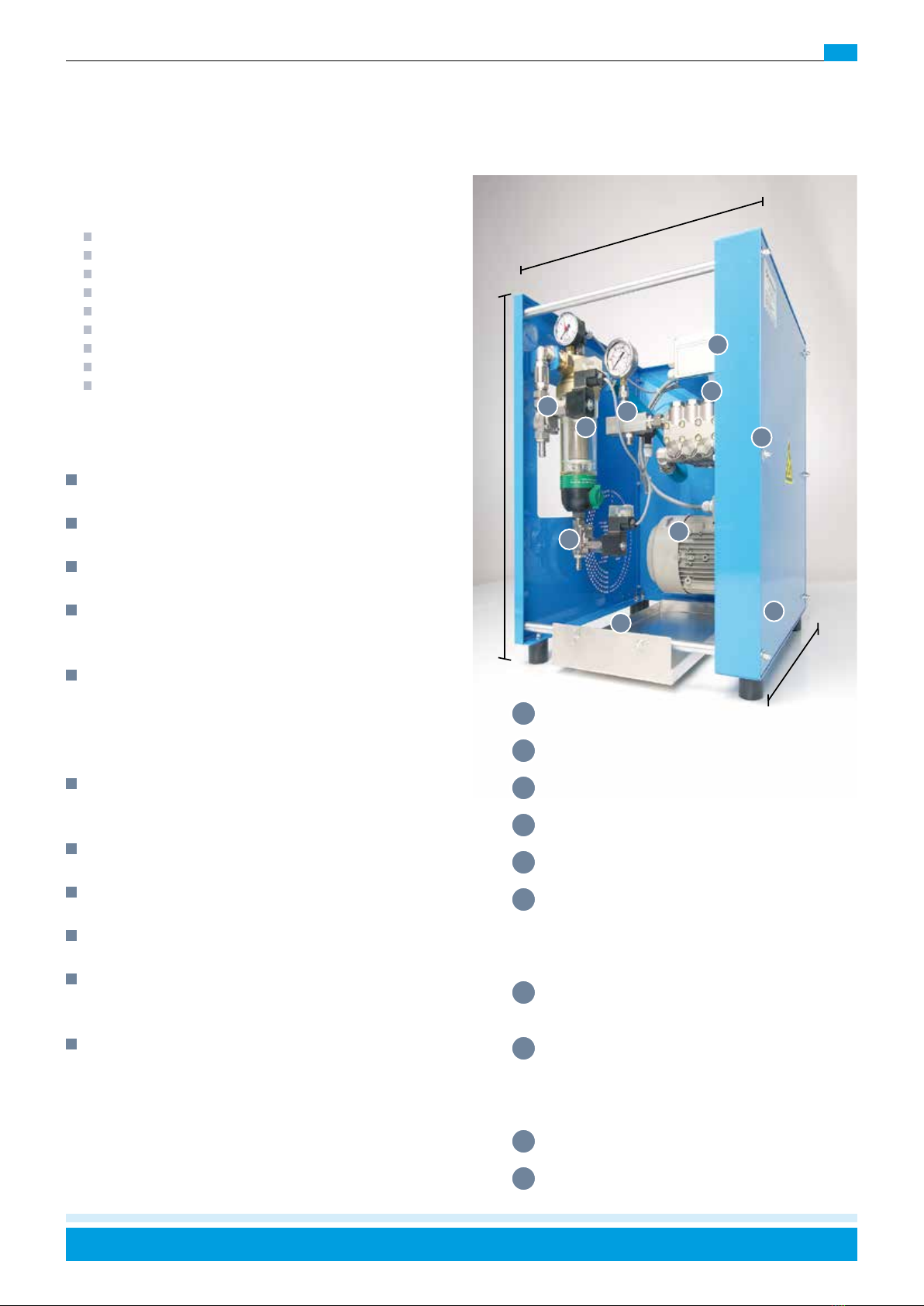
The maximum input pressure of the pump assembly must
not exceed 5 bar. Operating at any higher a pressure will
damage the pump.
Prior to installation, the oil level should be checked and
adjusted as required.
The individual steps are described in detail in the installa-
tion section.
Achtung !
The pump assembly may only be used with the corre-
sponding humidifier. The pump must be operated with the
corresponding controller. Non-compliance will invalidate
any guarantee claims.
Verbindungsleitungen
The control unit must be wired according to the on-site
circuit diagram.
Motor and sensor cables must be laid separately and
shielded.
The pump assembly is equipped with pressure controllers
(D1-D2) on both the low and high-pressure sides. These
must always be connected to the respective controller
connections.
The water supply between the on-site water pipe and the
pump station input is connected via the 3 m long 1/2”
low-pressure hose supplied. Other hose lengths of up to
10m are also available.
The on-site water supply pipe to the pump must be con-
nected to the device in either rising or falling fashion. Any
forms of connection allowing air pockets to form must al-
ways be avoided. The connection hoses must be properly
sealed.
For the installation of the droplet separator and the nozzle sys-
tem, please observe the installation instructions provided by Klin-
genburg and enclosed with the delivery of your humidifier.
Û
Pump
Û
Caution !
Û
Connecting cables
Attention !
The entire Klingenburg humidifier
should be protected from frost!
!!
Any other use that does not conform to the intended use
described above is not permitted.
Such use and changes to hardware and software will re-
sult in the loss of any warranty claims.
Improper use
!
Attention !
Û
Observance of the assembly instructions

11
Assembly / Commissioning
To eliminate the risk of interference via the motor supply
cable, a shielded cable must be used for this.
A thermostatic contact must also be connected to protect
the motor against excessive overheating at low speeds. If
no thermostatic contact is connected, the motor guaran-
tee will be invalidated.
Klingenburg frequency converters FC-KB 0.55 to 2.2 op-
erate with an output voltage of 3 x 230 V. For this purpose,
the motor in the pump station must be delta-connected.
Delta-connection
Klingenburg frequency converters FC-KB 4.0 and 5.5 op-
erate with an output voltage of 3 x 400 V. For this purpose,
the motor in the pump station must be delta-connected
(Motor 400/690 Volt).
Star-connection
The CERTO FU allows the processing of the following
control signals
0 - 10 V
4 - 20 mA
The control signals should be connected to terminals 8
and 9. Terminal 9 is reference potential (mass).
Û
Motor connection
Û
Control signal connection
Û
Jumper setting
The CERTO controller lets you connect a special humidity
sensor (available as an accessory) directly to the device. It
is able to ensure the constancy of an adjustable humidity
value via the programming.
The humidity sensor is connected to the control unit as
follows:
Klingenburg - Humidifier
Pump assembly
Controller
are factory-coordinated to work together.
Accordingly, the individual components should not be ex-
changed for other parts! In this case, please always con-
sult with our head office.
Should you have any enquiries concerning the device or
its components, please always quote the type and num-
ber of the device.
Û
Humidity sensor connection
Û
Connection to controller
Û
Example type plate
Û
Components
Terminal sensor Terminal control unit
3 (+10 V input) 7 (+10 V output)
2 (signal output) 8 (0-10 V input)
1 (earth) 9 (earth)

12
Installation instructions
Mechanical section
1. The inventory audit allows any missing system compo-
nents required for commissioning to be determined
early. If significant deficiencies on CERTO are detect-
ed prior to commissioning (e.g. transport damage),
the commissioning should be ceased pending further
action or repair. Regardless of circumstances, con-
sult with Klingenburg GmbH on how best to proceed.
2. Checking of the piping between the pump station
and humidifier. Here, care should be taken to ensure
stress-free laying (no twists, kinks and air pockets). In
addition, the high-pressure hose should be installed
in a way that eliminates friction. (Risk of fraying dur-
ing pump operation). The connection fittings on the
humidifier or the pump station should be checked.
The check should be performed using two wrenches
for counterholding. The internal screw connections of
the pump station are factory-tightened and sealed.
Any subsequent adjustment will inevitably result in
leakages.
3. General visual inspection of the hose connections
within the pump station.
4. Checking the oil level of the pump via the dipstick at
the bleeder screw or via the sight glass. Where appli-
cable, the gear oil ISO VG 220 GL4 (e.g. Aral Degol
BG220) should be refilled.
5. Checking the proper connection of the water drain:
The drip molding via siphon has to be designed as a
free drain und must not be connected to the waste-
water network. The water trap in the siphon should be
filled before switching on the fans, otherwise the wa-
ter may stop flowing due to a vacuum in the device,
which can cause damage.
Û
Installation steps 1

13
Installation instructions
Electro-mechanical section
6. Check the inter-wiring of the Klingenburg components
and compare the same with the terminal connection
plan. If any deviation is detected, the terminal con-
nection plan takes priority. In the event of any doubt,
consult Klingenburg GmbH to prevent the risk of seri-
ous damage. Incorrect connection could damage the
controller, or the inputs and outputs on the construc-
tion side.
7. The jumper is to be connected according to the con-
trol signal.
8. The power and water supply can now be enabled and
the system is ready for commissioning.
9. Starting up the system manually to check the basic
functions between the Klingenburg humidifier and the
pump station. Rotational direction check of the drive
motor. The rotation direction arrow is situated on the
motor’s fan cover.
10. Checking of the technical specifications to be ob-
served. The system is operated in manual operation
up to the frequency limit specified on the pump data
sheet, and the actual and set point pressures are
compared. A deviation of +/- 10 % is permissible.
11. To check the low-pressure diaphragm pressure
switch (D1) on the feed water supply, the intake pres-
sure (flow pressure) should be reduced under 1.6 bar
at the pump station input by slowly closing the shut-
off valve for the water supply. The control must switch
off the motor and after 25 seconds a fault message
is triggered. If the pressure is allowed to return to
around 2 bar, the control switches the motor back on
once the fault signal has been acknowledged. If the
pressure drops under 1.6 bar for less than 25 sec-
onds, the system automatically resumes operation.
12. The control signal can now be transmitted to termi-
nals 8 and 9.
13. Programming the controller and adjusting for exter-
nal operation, see in the control section.
The Klingenburg air humidification system may only be
operated by Klingenburg or an authorized service partner.
An overview sketch can be found on page 46.
Û
Installation steps 2
!
Attention !

14
Hygienic requirements
General points
The requirements of the above-mentioned regula-
tions describe a minimum hygiene standard for ven-
tilation and air conditioning systems. The guideline
formulates requirements that must be met during the
planning, execution, operation and maintenance of air
handling systems in order to ensure hygienic operation.
VDI guidelines are part of the technical regula-
tions and describe the state of the art. In the event
of a dispute, these rules are used as a bench-
mark for compliance with the state of the art.
DIN 6022 applies to all air handling systems and units
and their central and decentralized components that influ-
ence the supply air quality in occupied rooms in buildings.
In developing the Klingenburg humidifier, Klingenburg
paid particular attention to ensuring that the design
was flawless from a hygienic point of view, and had
this tested and confirmed by a type examination car-
ried out by the DMT Test Center for Air Hygiene, Essen.
However, in addition to the humidifier design, the fun-
damental prerequisite for hygienically flawless op-
eration is the fulfillment of all requirements of VDI
6022 and VDI 3803 Part 1 with regard to the de-
sign, operation and maintenance of the entire air
handling system in which a humidifier is integrated.
Design of the system
All requirements of VDI 6022 and VDI 3803 Part 1 regard-
ing the design of the overall system (sequence of compo-
nents, filter classes, etc.) must be taken into account.
The air velocity must not exceed 3.5 m/s.
Controller System
The Klingenburg control unit enables periodic flushing of
the nozzle blocks and the water-carrying lines when the
humidifier is not in operation for a longer period of time.
See the Control section. In addition, the control of the sys-
tem must be designed to meet the requirements of VDI
6022.
Water supply
The feed water must at least meet the microbiologi-
cal requirements of the Drinking Water Ordinance
and the requirements of VDI 3803 (Tables A1 and A3).
Only water from reverse osmosis (permeate) between. 5
- 20 µS/cm and a water hardness <1°dH is to be used.
The water-carrying pipes are to be made of corrosion-re-
sistant materials, such as plastic or stainless steel.
The operator is responsible for ensur-
ing that the water is free of particles.
If the humidifier is shut down for more than one day,
the water treatment buffer tank must be emptied.
Thehumidifiertankisdesignedwithaslopeonallsidestothe
drain point.Theslope inthe airdirection isat least50 mm/m,
against the air direction 250 mm/m and laterally 10 mm/m.
The wastewater drain is to be equipped
with a suitable siphon and an open outlet.
Biocides (e.g. hydrogen peroxide) for the disinfection of
supply water may only be used if it can be ensured that
no residues of these substances can enter the supply air.
The supply water should be test-
ed regularly (e.g. every 6 months).
If the humidifier is disinfected with biocides
or similar substances, the absence of resi-
dues must be ensured before commissioning.
Inspection
Before commissioning the entire air handling unit, an ini-
tial hygiene inspection must be carried out in accordance
with VDI 6022.
Maintenance / operation
See also the section Operation / Maintenance. To ensure
continuous hygienic operation over the entire humidifica-
tion period, the measures prescribed in VDI 6022 must
also be observed.
In particular, we refer to the checklist described in VDI
6022.( Table 8 )
Failure to observe the above points will in-
validate the humidifier’s conformity with VDI
6022 and VDI 3803 Part 1.
Hygienic requirements of ventilation and air-conditi-
oning systems according to VDI 6022 and VDI 3803
Part 1

ZERTIFIKAT
Genehmigung zur Nutzung des Prüfzeichens
FREIWILLIGE PRODUKTPRÜFUNG
NACH VDI 6022-1:2018
–Geprüfte Hygieneeigenschaften –
TÜV NORD Systems GmbH & Co. KG, Hamburg (Deutschland),
bestätigt, dass das Luftbefeuchtungssystem
„CERTO“
die von VDI 6022-1 und VDI 3803-1 gestellten Hygieneanforderungen erfüllt.
Klingenburg International Sp. z o.o., Świdnica (Polen)
wird daher das Recht verliehen, das nachstehend abgedruckte Prüfzeichen
in Zusammenhang mit dem o. g. Produkt zu führen.
TÜV NORD Systems GmbH & Co. KG
Prüfstelle für Kälte-, Klima- und Lüftungstechnik
Dipl.-Ing. Monika Steimle
Essen, 12. April 2022
Die Zertifizierung basiert auf einer Baumusterprüfung der Luftbefeuchtungssysteme
und nicht auf einer ausgeführten Anlage.
Die Gültigkeit des Zertifikats beträgt 15 Monate.
Die Prüfzeichennutzung ist in dem zugehörigen Vertrag geregelt.
Digitally signed by Steimle
Monika
Date: 2022.04.12 15:34:27
+02'00'
15
Test certicate

16
Test certicate
Dieser Bericht umfasst 7 Seiten und darf nur vollständig und unverändert weiterverbreitet werden.
Eine Veröffentlichung bedarf unserer Zustimmung.
Alle Prüfergebnisse beziehen sich ausschließlich auf die untersuchten Prüfgegenstände.
Baumusterprüfung der Konformität mit der Richtlinie VDI 6022 Blatt 1 (Ergänzungsprüfung)
Prüfzeugnis 2022 –8119426854
Prüfzeugnis:
2022 –8119426854
Standort / Prüfgegenstand:
Hochdruckluftbefeuchtungssystem „CERTO“
Klingenburg International Sp.z o.o.
Niederlassung Deutschland
Gahlener Str. 250
46282 Dorsten
Prüfung vor Ort:
16.02.2022
Dokumentenprüfung:
bis einschließlich 25.02.2022
Ausstelldatum:
25.02.2022
Prüfer:
Daniel Michalek
DMT GmbH & Co. KG · Tremoniastraße 13 · 44137 Dortmund
DMT GmbH & Co. KG
Anlagen- & Produktsicherheit
Technische Gebäudesicherheit
Tremoniastraße 13
44137 Dortmund, Deutschland
Kontakt:
Daniel Michalek
Telefon 0231 5333 217
E-Mail daniel.michalek@dmt-group.com
TÜV NORD Systems GmbH & Co. KG
Frau Vera Gräff
Am TÜV 1
45307 Essen

17
Test certicate
Dieser Bericht umfasst 2 Seiten und 8 Seiten Anhang.
Die Prüfergebnisse beziehen sich ausschließlich auf die Prüfobjekte.
Die Veröffentlichung von Auszügen aus diesem Bericht ist nicht ohne schriftliche Genehmigung von TÜV NORD Systems GmbH & Co. KG gestattet.
Sitz der Gesellschaft
TÜV NORD Systems GmbH & Co. KG
Große Bahnstraße 31
22525 Hamburg
Tel.: 040 8557-0
Fax: 040 8557-2295
info@tuev-nord.de
www.tuev-nord.de
TÜV NORD GROUP
Vorsitzender des Aufsichtsrates
Dr. Dirk Stenkamp
Amtsgericht Hamburg
HRA 102137
USt.-IdNr.: DE 243031938
Steuer-Nr.: 27/628/00031
Komplementär
TÜV NORD Systems
Verwaltungsgesellschaft mbH, Hamburg
Amtsgericht Hamburg
HRB 88330
Geschäftsführer
Dr. Ralf Jung (Vorsitzender)
Silvio Konrad
Ulf Theike
Systems
PRÜFSTELLE FÜR KÄLTE-, KLIMA-UND LÜFTUNGSTECHNIK
Gesch.-Nr.: KKL/1005/20 Essen, 5. April 2022
Auftrags-Nr.: 81 19 33 75 82 DoKl/GrV
Bericht Nr.: TR-KKL-2022-013
Ergänzungsprüfung an einem Luftbefeuchtungssystem
in Hygieneausführung nach VDI 6022-1
Auftraggeber
Klingenburg International Sp. z o.o.
ul. Metalowców 5
58-100 ŚWIDNICA,
POLEN
Prüfobjekt
Luftbefeuchtungssystem „CERTO“mit einem zweistufigen
Aerosolabscheider aus Edelstahlstrick
Auftragsdatum
21.06.2021
Prüfziel
Ergänzungsprüfung zur Bestätigung der Eignung von
einem Aerosolabscheider in einem Luftbefeuchtungssystem
für den Einsatz in raumlufttechnischen Anlagen mit
erhöhten Hygieneanforderungen
Prüfgrundlagen
VDI 6022-1:2018-01
VDI 3803-1:2020
Prüfzeitraum
•Grundprüfung
•Ergänzungsprüfung
Juli 2019 bis Januar 2021
Juni 2021 bis Februar 2022
TÜV NORD Systems
GmbH & Co. KG
ISGBW Testing
Am TÜV 1
45307 Essen
Tel.: 0201 825 - 3204
GBTesting@tuev-nord.de
www.tuev-nord.de
TÜV®

18
Test certicate

19
Plannings informations
There must be a homogeneous flow profile in
air temperature and velocity on the upstream and
downstream sides. This applies in particular if the fan
is located directly on the air inlet side of the humidifier.
We recommend providing a stilling distance of approx.
1.0m.
An empty section of at least 700 mm in length should
be provided before and after the humidifier for
accessibility and maintenance. Please observe VDI
6022 and VDI 3803 Part 1 for this.
When designing the humidification chamber, the
requirements of the VDI 6022 must be taken into
account.
Fan arrangement / part-load operation in connection
with demand-based control / circulatory air operation:
=> When demand-based control of the volume
flow or circulatory air operation applies, a control-
range extension of the humidifier must be included.
During the expansion process, some of the nozzles
in operation will be shut off by a magnetic valve
depending on the motor frequency.
Filter layout before / after humidifier according to
DIN EN 13053 and VDI 6022
During the operation of the humidifier, the design data
to the order underlying must be observed!
Wear parts should be replaced regularly and are not
subject to the warranty.
A list of spare / wear parts can be found on page 21.
The room temperature during operation of the pump
station and the controller should be between 5 and
35°C.
The CERTO humidifier is not frost-proof and not suitable
for outdoor installation.
Air speed should be between 0.5 - 3.5 m/s within the
humidifier cross-section.
Operation of the humidifier exclusively with deionized
water (permeate) from the reverse osmosis system.
between electrical conductivity 5 - 20µS/cm.; degree of
hardness <1° dH at 20°C, PH - value: 7 +/- 1
The particle freedom of the water is up to the operator.
To guarantee operational reliability of the humidifier,
air quality must be ensured according to the current
standards, particularly when operating with circulating
air
When operating the humidifier only with a preheater,
a humidity limiter should be fitted downstream of the
humidifier.
In the event of the ventilation system malfunctioning,
to protect downstream components against moisture
damage, we recommend using materials resistant to
deionised water, such as seawater-resistant aluminium
or stainless steel. Galvanised materials should include
a powder coating. In addition, a drain pan should be
included.
The operator must ensure that the pump station and
hose lines are monitored for leaks or hose ruptures.
To ensure trouble-free operation of the Klin-
genburg humidifier, the ventilation system
should meet the following requirements:
!Attention !

20
20
Plannings informations
Cleaning and disinfection
General points:
Despite the high level of water purity (permeate), hu-
midity chambers, in which the humidity is adjusted via
high-pressure humidifiers, must be regularly cleaned and
disinfected.
VDI 6022 stipulates that hygiene inspections must be
performed at regular intervals. In HVAC systems includ-
ing humidifiers, the systems must be checked every two
years by specially trained personnel and the minimum
requirements specified (e.g. VDI 6022 must be met.
Frequency:
Depending on the level of soiling, generally 2-3 times per
period of operation, see also VDI 6022, but a minimum
of every 6 months. Since the level of air pollution may
vary, the operator is responsible in this case for ensuring
that the recommended maintenance intervals suffice. In
accordance with DIN 6022 the hygienist must determine
how often maintenance intervals should be performed.
Note:
When using separate cleaning agents and disinfect-
ants, care should be taken to ensure that the use of the
cleaning agent does not compromise the disinfectant in
any way.
Relevant components:
Droplet separator
Nozzle holders incl. nozzles
Drip tray, side walls in the rear area of the device
Drainage
Cleaning agent:
Before using cleaning agents, ensure that the safety data
sheets and the notes of the respective manufacturers
have been read and observed.
For limescale deposits:
Cleaning agent that can reliably remove all limescale de-
posits must be used.
or:
Vinegar-based cleaner
For easily water-soluble deposits:
Warm water (40 - 60°). You may use a high-pressure
cleaner. Do not aim the water jet directly at the seals and
lighting!
Desinfection:
After the preliminary cleaning, a suitable surface disin-
fectant must be used. We recommend the use of Incidin
Extra N by ECOLAB for example. For the intended use of
this product please pay attention to the manufacturer´s
instructions.
Protection regulation:
Safety glasses
Rubber gloves
Half mask (respiratory protection) with minimum E-filter
and protection level P3
Sturdy shoes
Important notes:
Shoes or boots which come into contact with the hu-
midifier chamber must be clean and disinfected!
After an extended period of operation, deposits in the
device are likely. The type of minerals and quantity of
deposits depends on the water quality and, where appli-
cable, on the air quality (dust content etc.). In most cas-
es, these deposits tend to consist of lime (CaCO³) and
plaster (CaSO4). Operating the CERTO with permeate
produced via reverse-osmosis ensures that no impu-
rities will be introduced via the water. Due to possible
airborne impurities, e.g. during circulatory air operation
in production facilities, insufficient air filtration may lead
to these contaminants being deposited in the humidifier.
The seal of the access panel must be carefully checked
for any damage, and immediately replaced if any dam-
age is detected.
Interim cleaning during
humidification periods
Interim cleaning involves either all or part of the following
sets of maintenance work.
Final cleaning, preparation for humidificati-
on downtime
During final cleaning, all the following maintenance instruc-
tions should be taken into consideration.
Other manuals for CERTO
1
This manual suits for next models
5
Table of contents