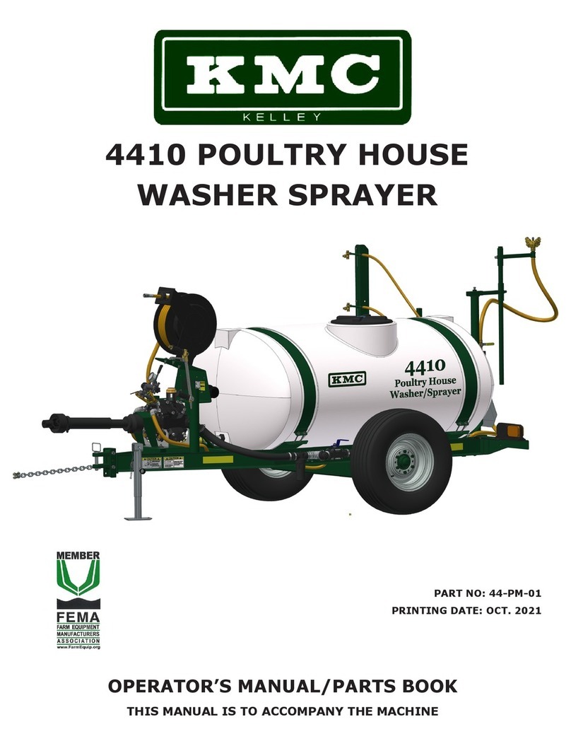
KMC Controls 44 Series User manual

4400
POULTRY HOUSE
WASHER/SPRAYER
(WITH JOHN BLUE PUMPS)
44-SERIES
PART NO. 44-OM-02
PRINTING DATE: AUG 2014
THIS MANUAL TO ACCOMPANY MACHINE
OPERATOR’S MANUAL

WARRANTY POLICY
KELLEY MANUFACTURING COMPANY (KMC) warrants that all goods sold
to the original purchaser of any KMC product shall be free of any defects in
material and workmanship if used under normal operating conditions. The
warranty period begins on the date of purchase by the retail customer. For
non-commercial users the warranty ends twelve (12) months thereafter. For
commercial users the warranty period ends six (6) months thereafter. KMC’s
sole responsibility is to repair and/or replace the defective part or parts at no
cost to purchaser. This remedy is the SOLE AND EXCLUSIVE REMEDY of
purchaser.
The purchaser must fill out and return the warranty registration form found in
the front of the operator’s manual. Failure to return the warranty registration
form within 30 days shall result in the goods being sold “AS IS”, and all
warranties shall be excluded.
This warranty shall not apply to those items that are by nature worn in
normal service, including but not limited to belts, springs, teeth, chains, etc.
Items such as tires, tubes, and gearboxes and all other items warranted by the
original manufacturer are warranted only to the extent of their individual man-
ufacturer warranty, and KMC is not warranting any of said items. All warran-
ty claims must be made through a KMC licensed dealer, and a warranty form
request must be submitted to KMC within 30 days of failure or the warranty pro-
vision shall be unenforceable against KMC.
No agent or person has authority to change or add to this warranty as written.
THE ABOVE IS THE ONLY WARRANTY MADE BY KMC AND IS MADE
EXPRESSLY IN LIEU OF ALL OTHER WARRANTIES, EXPRESSED OR
IMPLIED. KMC MAKES NO WARRANTY OF MERCHANTABILITY AS TO ANY
GOODS MANUFACTURED BY KMC AND FURTHER, KMC DOES NOT
WARRANT ANY SUCH GOODS AS SUITABLE FOR ANY PARTICULAR PUR-
POSE TO THE RETAIL CUSTOMER. THE SUITABILITY OF GOODS FOR
ANY PURPOSE PARTICULAR TO THE CUSTOMER IS FOR THE
CUSTOMER, IN HIS SOLE JUDGEMENT, TO DETERMINE. KMC FURTHER
MAKES NO WARRANTIES WITH RESPECT TO ITS MANUFACTURED
GOODS THAT WOULD NORMALLY BE DISCLOSED BY AN EXAMINATION.
THIS IS THE FULL AND FINAL EXPRESSION OF ALL WARRANTY LIABILITY
OF KMC. NO OTHER WARRANTY, EITHER EXPRESSED OR IMPLIED,
SHALL BE ENFORCEABLE AGAINST KMC.
Kelley Manufacturing Co.
80 Vernon Drive / Zip 31794
P.O. Drawer 1467 / Zip 31793
Tifton GA

1
TO THE PURCHASER
This KMC Poultry House Washer/Sprayer has been carefully designed and manu-
factured to give years of dependable service. In order to operate it efficiently and maintain if
properly, please read the instructions within this manual thoroughly.
While reading the manual through, you will notice that it is divided into sections which
clearly explain the assembly and operations of each components of this machine. A Table of
Contents is also provided for quick reference to these sections
Some components of this machine are labeled left or right. The notations are deter-
mined facing the direction the machine will travel in use.
After reading this Operator’s Manual, Please keep it for reference each season.
To insure procurement of the proper repair parts, please record your machine’s Serial
Number and Purchase Date as shown below:
Model No.____________________________
Serial No.____________________________
Purchase Date ________________________
This safety alert symbol is used throughout this manual to identify safety
messages. When you see this symbol, read the message which follows as
it will advise you of possible injury.

2
Retail Customers Responsibility Under The KMC Warranty
The retail customer’s responsibilities are:
1. To read the Operator’s Manual and operate the KMC Poultry House Washer/
Sprayer in accordance with instructions given in the manual.
2. To inspect the KMC Poultry House Washer/Sprayer daily, lubricate as specified
and repair or replace parts as needed, especially when continued use would cause
damage or excess wear to other parts.
3. To maintain and keep in place all safety shields and devices.
4. When Warranty Service is necessary, it is the customer’s responsibility to deliver
the machine to the KMC dealer from which is was purchased, Warranty repairs
should be submitted to the dealer within thirty (30) days of failure.
5. Dealer travel to the machine or hauling the machine to his shop for the purpose of
performing warranty service is not allowed under KMC warranty. It is a cost to be
paid for by the retail customer. Any arrangement whereby the dealer agrees to ab-
sorb all or part of this cost is strictly between the dealer and retail customer.
SAFETY PROCEDURES
Safety and performance are the primary objectives of the designers of KMC equipment.
Safety features have been incorporated into this machine where possible and warnings given
in other areas. For your safety, PLEASE read and observe the following safety procedures.
1. Do not permit anyone to ride on the machine.
2. Keep all persons a safe distance away from the rear and sides of the machines
while it is in operation.
3. Drive safely during transport; excessive speed while turning on rough ground or
over hills could cause tractor to tip over.
4. Make sure hitch components are attached securely before operating or transport-
ing.
5. Use flashing warning lights when on highways, except where prohibited by law.
6. Stop tractor engine before leaving operator’s position to adjust, lubricate, clean or
unclog machine.
7. Keep all shields in place.
8. Keep hands, feet and clothing away from moving parts.
9. Make sure everyone is clear of machine before starting tractor or operating ma-
chine.
10. DANGER! Install safety struts and pins prior to working under
machine. Failure to do so may result in serious injury or death.
11.Maximum towing speed is 20 MPH loaded -- 25 MPH empty.
12.Observe all safety decals located on machine.

3
TABLE OF CONTENT
TO THE PURCHASER.............................................................................................................. 1
Retail Customers Responsibility Under the KMC Warranty...................................................... 2
SAFETY PROCEDURES .......................................................................................................... 2
POULTRY HOUSE WASHER/SPRAYER BASIC FEATURES............................................. 4
MACHINE SETUP:
Attaching to Tractor........................................................................................................... 4
Positioning Sidewall Nozzle .............................................................................................. 5
Positioning Floor and Ceiling Nozzle................................................................................ 5
Setting Break-Away Boom Latch Pressure ....................................................................... 5
OPERATING INSTRUCTIONS:
Operating Pump ................................................................................................................. 6
Setting Pump Pressure ....................................................................................................... 6
Pump Discharge Controls .................................................................................................. 7
Boom Nozzle Controls....................................................................................................... 7
Washing Sidewalls or Curtains.......................................................................................... 7
Spraying/Washing Floor or Ceilings ................................................................................. 8
Spray Gun and Hose Reel .................................................................................................. 8-9
MAINTENANCE AND ADJUSTMENTS:
Pump Maintenance............................................................................................................. 10
Valve Assembly and O-Ring Replacement ....................................................................... 10
Diaphragm Replacement.................................................................................................... 10-11
Other Maintenance and Adjustments................................................................................. 11
LUBRICATION ......................................................................................................................... 12
TRANSPORTATION................................................................................................................. 12
STORAGE .................................................................................................................................. 12
SPECIFICATIONS..................................................................................................................... 13
TROUBLESHOOTING.............................................................................................................. 14
BOLT TORQUE SPECIFICATIONS ........................................................................................ 15
DECALS ..................................................................................................................................... 16

4
POULTRY HOUSE WASHER/SPRAYER BASIC FEATURES
Throughout this manual we will be discussing various features and components of the KMC
Poultry House Washer/Sprayer. References to var ious components for adjustments, settings,
performance, and lubrication are made. The following diagram will help in identifying these
components.
MACHINE SETUP
Attaching to Tractor
The KMC Poultry House Washer/Sprayer is designed to be operated from the stationary
drawbar of the tractor. If the tractor being used has an option of a 540 or 1000 RPM PTO shaft, you
should install the 540 shaft.
Once the tractor has been set, attach the Poultry House Washer/Sprayer to the tractor drawbar
using an appropriate hitch pin. With the tractor and the Washer/Sprayer sitting on level ground, note
the position of the front and rear of the washer frame. Ideally, the rear of the washer frame should be
level with or higher than the front. This minimizes possible damage to the rear spray boom caused by
crossing bumps or dips. If the rear of the frame is lower than the front and the adjustable hitch is not
already in the top position, disconnect the washer from the tractor and move the hitch to the top
position. Re-attach the Washer/Sprayer to the tractor.
The end of the PTO driveline with the small diameter shield attaches to the pump. Attach the
driveline to the pump drive shaft by twisting the locking collar and pushing the driveline onto the drive
shaft. Release the collar and continue to push the driveline onto the drive shaft until the collar locks.
Follow the same procedure and attach the PTO driveline tractor end to the tractor PTO shaft. Make
sure the PTO driveline shielding rotates freely on the driveline. Attach the safety chains, allowing
sufficient slack for turns.
HOSE REEL
PUMP
SPRAY GUN
CONTROL UNIT
PTO
DRIVELINE
STRAINER
INLET VALVE

5
Positioning Sidewall Nozzles
The four sidewall nozzles can be adjusted vertically and horizontally as well as rotated vertical-
ly and horizontally. Horizontal and vertical adjustments (moving nozzles closer to or further away
from wall and up or down) are made by loosening setscrews and sliding the boom extensions or nozzle
brackets. Nozzles are rotated vertically by loosening the nozzle arm attachment bolt and rotating the
nozzle arm. The swivel nozzle bodies provide horizontal rotation.
Place the wash-
er/sprayer at the de-
sired distance from the
wall to be washed. Ad-
just nozzles to cover the
desired height on the
wall. Make sure nozzle
spray tips are posi-
tioned to provide a ver-
tical, flat, spray pat-
tern. Make sure nozzle
spray patterns will over-
lap providing complete
coverage. It may be
necessary to temporari-
ly operate the pump
during the nozzle
adjustment process to
observe spray patterns
and make adjustments.
Positioning Floor and Ceiling Nozzles
Setting Break-Away Boom Latch Pressure
The 3/4” double swivel spray nozzle is for use in spraying floors and washing ceilings. For
spraying floors the nozzle should be turned downwards. The width covered by the nozzle is adjusted
by changing the angle of the tips and/or lowering or raising the nozzle. Air movement can greatly
decrease spray coverage. It may be desirable to close doors on the house or to spray one-half of the
house per pass. To wash or spray ceilings, invert the double swivel nozzle to point the tips upward.
The nozzle is inverted by loosening the setscrew on the nozzle support and inverting the support on
the extension arm. The nozzle can be brought closer to the ceiling by extending the extension arm.
With the nozzle raised, care must be taken to avoid hitting obstacles, e.g. raised watering equipment.
The amount of force required to release the break-away boom can be adjusted by loosening or
tightening the boom latch bolts. This will decrease or increase the amount of load on the latch springs.
Check the latch pressure by forcefully and quickly pushing against the wall nozzle arm. The latch
pressure should be checked with the wall nozzle boom extension in the retracted position..
EXTENSION ARM
FLOOR/
CEILING
NOZZLE
NOZZLE
SUPPORT
BOOM LATCH
BREAK-AWAY
BOOM BOOM EXTENSION
SIDEWALL
NOZZLES

6
OPERATING INSTRUCTIONS
Operating Pump
Do not operate the pump above 540 RPM. When the pump is operating, check the oil level in
the sight glass
IF THE OIL SUDDENLY TURNS WHITE STOP THE PUMP IMMEDIATELY. THIS
INDICATES THAT A DIAPHRAM HAS RUPTURED. IF THE OIL LEVEL RISES TO
THE TOP OF THE SIGHT GLASS DUE TO HIGH OPERATING TEMPERATURE ,
STOP THE PUMP TO PREVENT DAMAGE FROM INTERNAL OVERPRESSURE.
Setting Pulsation Damper and Pump Pressure
THE PUMP PRESSURE SHOULD BE SET WITH ALL DISCHARGE IN BYPASS
LINE ONLY. ALL OTHER DISCHARGE LINES SHOULD BE CLOSED. This prevents ex-
ceeding the maximum pump pressure rating. For example, if the pressure was set at or near maximum
pump pressure with one or more nozzles turned on , when these nozzle (s) were turned off, the
pressure would rise above the pump’s maximum pressure rating. If the maximum pump pressure is ex-
ceeded, liquid will exit from the safety valve, this is normal. The recommended pressure setting for
most operations is 600 psi. With the pump not running check pulsation damper with pressure gauge.
Inflate to 100 psi if required. (Check on regular intervals before running)
Before setting the pump pressure, make
sure there is liquid in the tank and the inlet
valve is open. Close all discharge valves, place
the pressure release lever in the down position,
and loosen the jam nut on the pressure adjust-
ment knob shaft. Engage the tractor PTO and
increase the engine speed to attain the PTO
working speed, do not exceed a PTO speed of
540 RPM. Set the pressure by observing the
control unit pressure gauge and turning the
pressure adjustment knob clockwise to increase
pressure or counterclockwise to decrease
pressure. After the pump pressure is set, tighten
the adjustment knob shaft jam nut and disen-
gage the tractor PTO.
RE-CIRCULATION
CONTROL
VALVE
SPRAY GUN
CONTROL
VALVE
BOOM
CONTROL
VALVE
STRAINER
PRESSURE
GAUGE
PRESSURE
ADJUSTMENT
KNOB
PRESSURE
RELEASE
LEVER
PRESSURE
CONTROL
UNIT
INLET VALVE
(Open Position) Must be installed with
arrow from tank toward
inlet side of pump
AIR VALVE STEM
(Test with air gauge &
set at 100 PSI)

7
Pump Discharge Controls
Three valves control the discharge of liquid to the rear boom, the spray gun, and the
re-circulating line. The valves that control the discharge to the boom and spray gun are located on the
right side of the pump housing. (On pumps prior to 6/96, valves are located on the left side of pump.)
The valve controlling the re-circulating line is located on the pressure control unit. Normally, the
valves controlling the boom and spray gun discharge lines should be fully opened when either of these
components are to be used. The valve controlling the re-circulating line can be left in the closed posi-
tion if only water is being used. If a disinfectant or other chemical and water mixture is being used,
the re-circulating feature can provide agitation of the mixture. Fully opening the re-circulating valve
will greatly decrease the pump pressure; therefore, only partially open the valve.
Boom Nozzle Controls
On the poultry house washer/
sprayer, each wall nozzle, as well as the
floor/ceiling nozzle are independently
controlled with valves. These valves are
located on the distribution manifold at
the rear of the washer/sprayer.
Washing Sidewalls or Curtains
Place the four valves that control the wall
nozzles in the open position. Make sure the valve at
the pump that controls the boom discharge line is
open. Make sure the break-away feature of the boon
is operational. Engage the tractor PTO and bring the
engine up to PTO working speed.
It is recommended that two passes be made
for each wall. The first pass wets the material and
aids in loosening it for removal by the second pass.
For maximum cleaning, the sprayer should be
operated at a ground speed of 1 to 3 mph. However,
this may vary depending on the degree of build-up
on the wall or curtains.
FLOOR/CEILING VALVE
WALL NOZZLE VALVES

8
Spraying/Washing Floors or Ceilings
If a disinfectant or other chemical is added to the tank, use the recirculation feature to agitate
the water/chemical mixture. Allow the mixture to agitate for several minutes before spraying.
Floors can normally be sprayed in one pass through the house. After positioning the 3/4”
double swivel nozzle for spraying floors, open the control valve located on the distribution manifold.
Make sure the valve at the pump that controls the boom discharge line is open. Engage the tractor PTO
and bring the engine up to PTO working speed.
Place the 3/4” double swivel nozzle in the inverted position with the tips upward for washing
ceilings. To wash the entire ceiling and obtain maximum cleaning, 2 to 4 passes through the house
may be required.
Spray Gun and Hose Reel
Operating the spray gun requires the operator
to be off the tractor and in a standing position.
Engage the tractor PTO and bring the engine up to
PTO working speed. After dismounting the tractor,
open the spray gun discharge valve at the pump.
The hose reel is spring-loaded which pro-
vides automatic rewinding of the spray gun hose.
Pull the required amount of hose from the reel by
grasping the hose. To lock the reel in position, pull
BEFORE DISMOUNTING THE
TRACTOR, PLACE THE TRACTOR
TRANSMISSION IN PARK (OR NEU-
TRAL IF TRACTOR HAS NO PARK
POSITION) AND LOCK THE WHEEL
BRAKES.

9
DUE TO THE FORCE OF THE WATER EXITING THE SPRAY GUN,
SUBSTANTIAL RECOIL IS PRODUCED. WHEN OPERATING THE SPRAY
GUN, FIRMLY GRASP THE GUN WITH BOTH HANDS.
the hose until an audible “click” is heard in the reel, then slowly release the hose. To rewind the hose,
first pull a few inches of hose from the reel to unlock the reel locking mechanism. While holding the
hose, allow the reel to rewind the hose. The spray pattern of the gun can be adjusted by rotating the
forearm handle.

10
Valve Assembly and O-Ring Replacement
MAINTENANCE AND AD-
Pump Maintenance
After a chemical and water mixture
has been used with the washer/sprayer,
the pump should be operated at working
pressure with clean water for a few
minutes. Afterwards, let the pump
pressure drop to zero and operate the pump
without liquids for two minutes. Running
the pump without liquids can be accom-
plished by completely emptying the tank or
closing the inlet valve and removing the
strainer.
If the pump will experience
freezing conditions, empty the pump
completely. If the pump will be stored for
long periods, some of which will be under
Diaphragm Replacement
The pump diaphragms should be changed
after every 500 hours of use. When replacing di-
aphragms, follow these steps referring to the dia-
gram:
1) Drain the oil from the pump by removing the
cap from the oil site glass, removing the pump
mount bolts and loosening the necessary hoses.
Turn the pump upside down and rotate the
crankshaft until oil stops flowing out.
Occasionally debris can cause the valves to
not seat properly or damage o-rings. To check this
problem follow these steps, referring to diagram.
1) Remove valve cover, valve assembly and
O-rings.
2) Check the valve assembly for debris and both
the valve assembly and o-rings for wear.
3) Replace parts as necessary consulting the parts
list for valve or o-ring part numbers.
freezing conditions, an extra precautionary measure is to flush the pump with a 50/50 anti-freeze and
water mixture.
The pump has an internal pulsation dampener which aids in smoothing out the discharged liquid
flow. The pressure in this dampener is set and checked through an air valve stem located at the front of
the pump. The pressure should periodically be checked using an automotive air gauge without pump
running. As a general rule, set pulsation dampener to 1/3 the working pressure without exceeding 100
psi. For example: if the pump will be operated from 300-700 PSI, the pulsation dampener pressure
should be set 100 PSI.
AIR VALVE
STEM
PUMP HEAD
VALVE COVER
VALVE COVER
VALVE ASSEMBLY
VALVE
ASSEMBLY
PISTON
DIAPHRAGM
PUMP HEAD

11
2) Remove the pump head.
3) Rotate the crankshaft to bring the diaphragm clamping bolt out as far as possible.
4) Using a hex wrench, remove the diaphragm clamping bolt; diaphragm cap, and diaphragm.
5) Before installing the diaphragm, rotate the crank shaft until the piston is at the bottom of its stroke.
6) Install the new diaphragm onto the piston tightening the clamping bolt to a torque of 18.5 ft lbs.
7) Insert the edge of the diaphragm into the grooves in the piston sleeve.
8) Replace the head.
Repeat steps 2 thru 8 for each diaphragm being replaced.
Other Maintenance and Adjustments
The environment that the washer/sprayer is used in can be highly corrosive to steel components.
Therefore, to protect painted surfaces, the washer/sprayer should be washed off after each use.
Periodically clean the inlet strainer and the nozzle tips.
The tank hold-down straps should be checked periodically for tightness. Temperature changes,
vibration, and settling of the tank may cause them to loosen. Check the straps with the tank at least 3/4
full. Tighten the straps by tightening the nuts on the bolts that attach the straps to the tank saddle.
Periodically check all hose clamps, fittings, and valves for tightness. Replace worn, cracked, or
leaking hoses.
The spring tension on the hose reel can be adjusted by adding or removing wraps of hose from
the spool. Add wraps to increase tension and remove wraps to decrease tension. Add or remove wraps
one at a time until desired tension is reached.
CAUTION: REEL IS UNDER TENSION. USE EXTREME CAUTION WHEN
ADJUSTING SPRING TENSION. ADJUST WITH LATCHING MECHANISM
ENGAGED.
CAUTION: DO NOT ATTEMPT TO DISMANTLE REEL. A HIGH TENSION
SPRING ASSEMBLY IS CONTAINED WITHIN THE REEL. IMPROPER
REMOVEL OF THE SPRING COULD RESULT IN PERSONAL INJURY AND/
OR REEL DAMAGE.
PUMP SITE GLASS
9) Using a SAE 30W non-detergent oil, refill the pump
through the site glass to the proper level. Rotate the
crankshaft while filling to distribute the oil.
10) Before putting the cap back on the oil site glass, run the
pump with no pressure (raise the control unit pressure
release lever) until all air bubbles are vented.
11) After replacing the cap on the oil site glass, check the oil
level with the pump operating with pressure.

12
LUBRICATION
It is very important to maintain the proper oil level in the pump crankcase. The oil level is
checked via the site glass located on the top of the pump. The pump requires a SAE 30W non
-detergent oil.
The pump crankcase oil should be changed after every 500 hours of use or when the pump
diaphragms are replaced. The oil is changed as follows:
1) Drain the oil from the pump by removing the cap from the oil site glass, removing the pump mount
bolts and loosen the necessary hoses. Turn the pump upside down and rotate the crankshaft until oil
stops flowing out.
2) It is recommended that the inside of the pump crankcase be washed with gasoline or diesel oil.
3) Using a SAE 30W non-detergent oil, refill the pump through the site glass to the proper level.
Rotate the crankshaft while filling to distribute the oil.
4) Before putting the cap back on the oil site glass, run the pump with no pressure (raise the control
unit pressure release lever) until all air bubbles are vented.
5) After replacing the cap on the oil site glass, check the oil level with the pump operating with
pressure.
The PTO driveline should be greased as follows: Grease the universal joints and shield fitting
after every 8 hours of use. Grease the locking collars and driveline tubes after every 20 hours of use.
TRANSPORTATION
Before towing the washer/sprayer for extended distances, make the following preparations:
Remove the PTO driveline, detaching it from the pump. Secure the spray gun in the holster. Secure
the break-away boom with a rope, rubber strap, etc. to prevent it from opening when crossing rough
areas such as railroad crossings. Maximum towing speed is 25 MPH.
STORAGE
The Poultry House Washer/Sprayer should be washed down thoroughly. After washing, treat-
ing with a disinfectant is recommended to kill any remaining bacteria. Treat the metal components of
the machine with a soluble oil to protect from rust and corrosion. One product which meets these re-
quirements is called “Film Fluid” manufactured by Eureka Chemical Co., San Francisco, CA. It is sold
in some tractor dealerships and farm supply dealers.
If the pump will experience freezing conditions, empty the pump of water completely. An extra
precautionary measure is to flush the pump with a 50/50 anti-freeze and water mixture.

13
SPECIFICATIONS
Weight: 1100 lbs
Width: 77 inches
Height: 61 inches
Length: 14 feet
Tire Size: 11L x 15 (6 ply)
Pump: PTO dr iven diaphr agm produces maximum pr essur e of 725 psi and maximum
flow rate of 39.5 gpm. Maximum 540 rpm PTO speed.
Tractor Size: Minimum 30 horsepower with 540 rpm PTO.
Hitch: Clevis Type.
Axle: Solid with replaceable hub assembly.
Rear Boom: Has break-away feature which causes boom to swing open if immovable ob-
ject is contacted.
Liquid Flow Control: All spr ay nozzles ar e individually controlled with 90 degr ee tur n,
ball valves.
Spray Gun: 21” wand, 850 psi maximum, 30 gpm maximum with adjustable spray pat-
tern.
Tank: 500 gallon elliptical polyethylene.
Reel: Spr ing r ewind, capacity of 50 ft of 1/2 inch hose.

14
TROUBLESHOOTING
TROUBLES CAUSES CURES
The pump doesn’t
reach the required
pressure
Valves have worn seats
Suction hose with air pockets
or irregular elbows
Worn nozzles
Clogged strainer
Check valves
Check hose
Check nozzles
Clean strainer
The pressure
gauge fluctuates
Pump is sucking air, or air
hasn’t been evacuated
completely.
Valves blocked
Start pump with the gun open,
to evacuate the air
and commutate.
Clean or change valves
The liquid flow
is irregular
The air in the pulsation damper
is incorrectly set.
Check pressure in pulsation
damper. Should be 8-10% of
operating pressure.
Output drops and
the pump is noisy Oil level is too low
Top up with oil to correct level
(halfway of the site glass),
when pump is operating.
Oil comes out of
the discharge pipe
One or more diaphragms are
broken. Stop pump immedi-
ately
Drain the pump of oil. Disman-
tle heads and change dia-
phragms. Fill with oil to correct
level.
Oil is changing col-
or into white
Diaphragm failure (s). Stop
pump immediately
Drain the pump of oil. Disman-
tle heads and change dia-
phragms. Fill with oil to correct
level.

15
30 to 35 FT-LBS
18 FT-LBS
14.5 FT-LBS
14.5 FT-LBS
14.5 FT-LBS

16
IMPORTANT!
1. Do not exceed maximum pump pressure rating (725 PSI).
2. Set pressure with outflow in bypass line only, all other discharge lines should be
closed.
3. If the oil in the site glass turns white, stop the pump immediately. Consult
TROUBLESHOOTING section of owner’s manual.
4. Do not leave water in pump during freezing conditions. Consult MAINTENANCE
AND ADJUSTMENTS section of owner’s manual.
Pump Warranty does not apply to damage caused by:
1. Exceeding maximum pump pressure.
2. Freeze damage.
3. Exceeding operating speed of 550 RPM.
4. Operating the pump with excessive angle at driveline/pump connection caused
by sharp turning radius.
5. Operating pump and damaged diaphragm (s).
6. Low oil level.

YEAR SERIAL NUMBERS
1985 27986-29695
1986 29696-31095
1987 31096-33234
1988 33235-35548
1989 35549-38496
1990 38497-41771
1991 41772-44466
1992 44467-47001
1993 47002-48750
1994 48751-51549
1995 51551-54262
1996 54263-56661
1997 56662-59465
1998 59466-62097
1999 62098-63986
2000 63987-65692
2001 65693-67340
2002 67341-68699
2003 68700-70482
2004 70483-72646
2005 72647-74866
2006 74867-76368
2007 76369-77883
2008 77884-79891
2009 79892-80944
2010 80945-81775
2011 81776-83453
2012 83454-85092
2013 85093-86418
2014 86419-87790
2015 87791-89096
2016 89097-
The following is a list of serial numbers issued to our machines at the beginning of each
year. To determine when a unit was made, find the range within which the particular serial
number falls. It would have been produced between January 1 to December 31 of that year.

DEPENDABLE EQUIPMENT FOR PROGRESSIVE FARMIMG
KELLEY MANUFACTURING CO.
80 Vernon Drive / Zip 31794
P.O. Drawer 1467 / Zip 31793
Tifton, GA
Tel: 229-382-9393
Toll Free: 1-800-444-5449
Fax: 229-382-5259
Email Address: info@kelleymfg.com
Visit us at www.kelleymfg.com
MADE IN AMERICA
This manual suits for next models
1
Table of contents
Other KMC Controls Paint Sprayer manuals