Table
of Contents
Introduction 2.
. . . . . . . . . . . . . . . . . . . . . . . . . . . . . . . . . . .
Warnings 4
. . . . . . . . . . . . . . . . . . . . . . . . . . . . . . . . . . . . . .
Setup 7
. . . . . . . . . . . . . . . . . . . . . . . . . . . . . . . . . . . . . . . . .
Startup 9
. . . . . . . . . . . . . . . . . . . . . . . . . . . . . . . . . . . . . . . .
Shutdown
and Care
11.
. . . . . . . . . . . . . . . . . . . . . . . . . .
Flushing 12
. . . . . . . . . . . . . . . . . . . . . . . . . . . . . . . . . . . . .
Troubleshooting 13
. . . . . . . . . . . . . . . . . . . . . . . . . . . . . . .
Spin Test 18.
. . . . . . . . . . . . . . . . . . . . . . . . . . . . . . . . . . . .
General
Repair Information
19.
. . . . . . . . . . . . . . . . . . . .
Motor
Brush Replacement
20.
. . . . . . . . . . . . . . . . . . . .
Power
Supply Cord Replacement
21.
. . . . . . . . . . . . . .
On/Off
Switch Replacement
22.
. . . . . . . . . . . . . . . . . . .
Pressure
Control Replacement
23.
. . . . . . . . . . . . . . . .
Bearing
Housing & Connecting Rod Replacement
25.
Drive
Housing Replacement
26.
. . . . . . . . . . . . . . . . . . .
Motor
Replacement
28.
. . . . . . . . . . . . . . . . . . . . . . . . . . .
Displacement
Pump Repair
30.
. . . . . . . . . . . . . . . . . . . .
Parts
Drawing – Sprayer
34.
. . . . . . . . . . . . . . . . . . . . . .
Parts
List – Sprayer
35.
. . . . . . . . . . . . . . . . . . . . . . . . . .
Parts
Drawing and List – Displacement Pump
36.
. . . .
Parts
Drawing – Pressure Control
37.
. . . . . . . . . . . . . .
Parts
List – Pressure Control
37.
. . . . . . . . . . . . . . . . . .
Wiring
Diagram
38.
. . . . . . . . . . . . . . . . . . . . . . . . . . . . . .
Accessories 39
. . . . . . . . . . . . . . . . . . . . . . . . . . . . . . . . . .
Technical
Data
39.
. . . . . . . . . . . . . . . . . . . . . . . . . . . . . . .
Dimensions 39
. . . . . . . . . . . . . . . . . . . . . . . . . . . . . . . . . . .
Warranty
And Disclaimers
40.
. . . . . . . . . . . . . . . . . . . . .
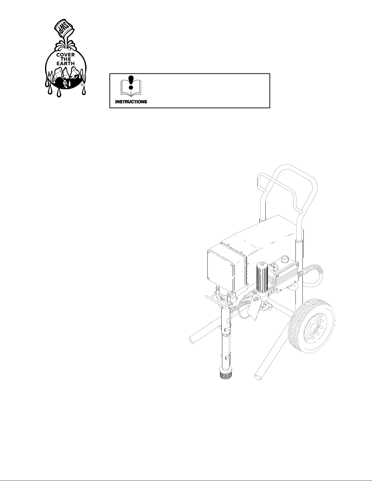
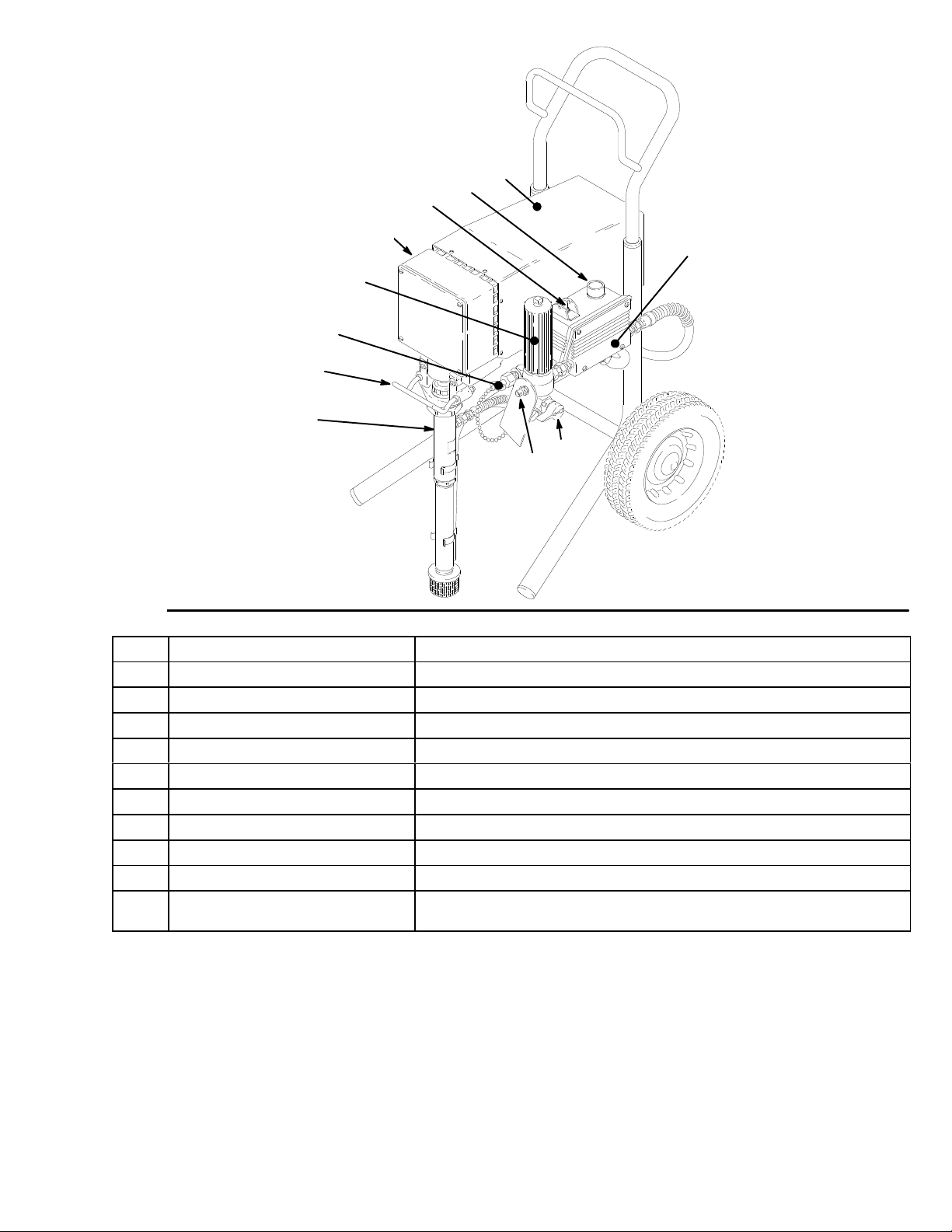
Introduction
ULTIMATE
Plus+
1000
BASIC COMPONENTS
Your
new sprayer functions and operates dif
ferently than
other
airless paint sprayers. This section will help you be
-
come
familiar with the sprayer before operating it.
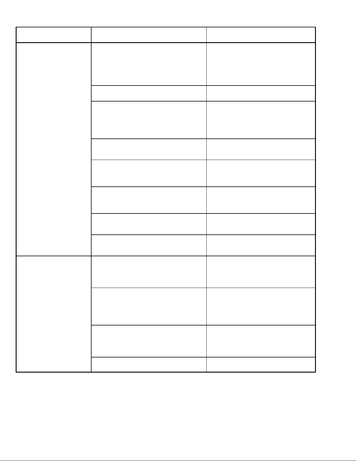
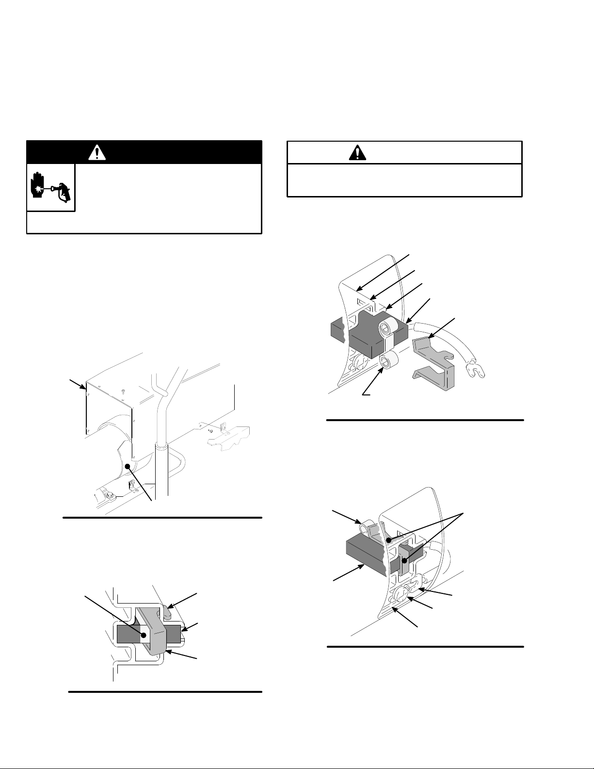
Pressure Control
The
pressure control includes
an ON/OFF switch for the
sprayer, a pressure adjusting control knob and a freeze
resistant pressure sensing device. The function of the
pressure
control is to control the
motor speed so that the
sprayer maintains constant fluid pressure at the pump
outlet.
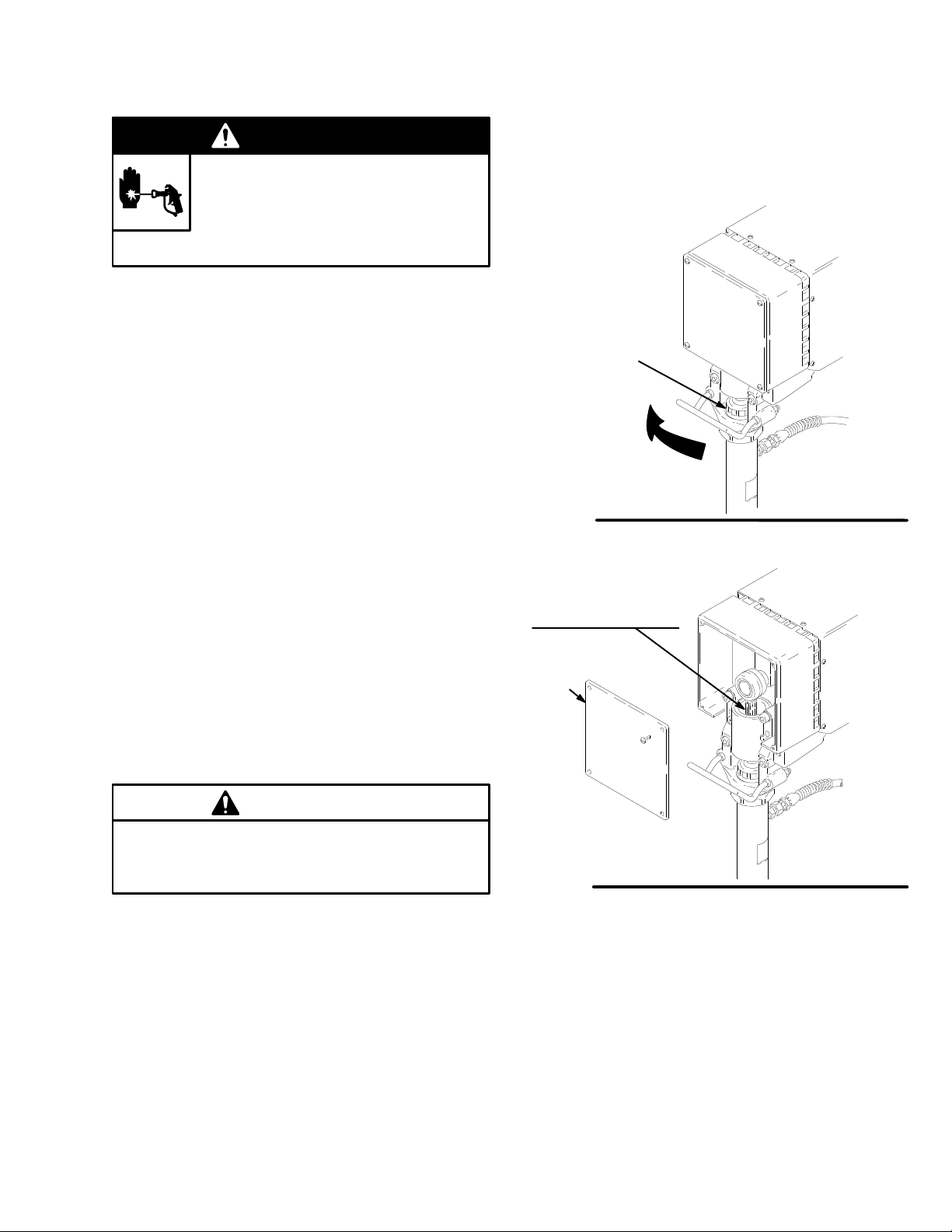
Pressure
Drain V
alve
The pressure drain valve provides pressure relief of the
sprayer.
In the forward position, the drain valve is closed
and allows normal sprayer operation. In the downward
position, the pressure drain valve relieves the pressure
in
the system. The pressure drain valve will also open au
-
tomatically in the case of a control overpressure failure.
Motor
The
DC motor has sealed bearings and replaceable
mo
-
tor brushes. It drives the displacement pump at the rate
needed
to supply suf
ficient paint volume
at the selected
pressure. W orking together , the pressure control and
motor
cause the pump to cycle whenever there
is fluid or
pressure
demand.
When the pump is cycling, the motor
sounds like an automobile starter cranking. When the
pump
is not cycling, the motor may hum intermittently un
-
til
the fluid pressure stabilizes, then the motor will shut
it
-
self off. However, there will still be power to the sprayer
and it will stay pressurized and ready to use until you
manually
shut it of
f and relieve pressure.
Because the motor is DC, it is less sensitive to low volt-
age or voltage fluctuations than an AC motor , and a 12
gauge
or larger extension cord of up to 300 ft. (90 m) can
be
used without performance loss.
Drive Assembly
The
sealed drive assembly
transfers power from the DC
motor
to the displacement pump.
Displacement Pump
The
positive displacement, volume-balanced pump pro
-
vides
equal fluid delivery on both the up
and down pump
strokes. The pump has a wet-cup which, when filled with
Graco Throat Seal Liquid, helps prevent damage to the
throat
packings and piston rod.
Fluid Filter
The
fluid filter strains the paint to help avoid clogs in
the
hose
and spray tip. The filter includes a reusable element
and
has a pressure drain valve for manually relieving fluid
pressure.
Hoses
The
grounded, nylon spray hoses have spring guards on
both
ends. The 50 ft. (15.2 m) hose has a 1/4 in. ID. The
3 ft.
(0.9 m), 3/16
in. ID hose provides more flexible gun
movement. The nylon hose material acts
as a pulsation
dampener to absorb pressure fluctuations.
Spray Gun & RAC IV DripLess Tip Guard
Graco high pressure spray guns have a safety latch
which
prevents accidental
triggering when it is engaged.
See T in Fig. 1. The gun provided with the sprayer also
has
a filter for final paint straining. The Reverse-A-Clean
IV SwitchTip uses high pressure fluid to remove clogs
from
the
spray tip without removing it from the gun. The
Reverse-A-Clean IV DripLess tip guard is a safety fea-
ture
which helps reduce the risk of fluid injection injury
.