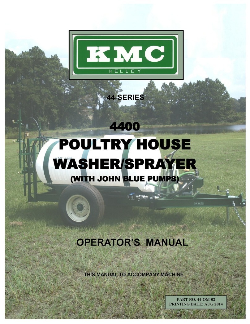
KMC Controls 4410 User manual

4410 POULTRY HOUSE
WASHER SPRAYER
OPERATOR’S MANUAL/PARTS BOOK
THIS MANUAL IS TO ACCOMPANY THE MACHINE
PART NO: 44-PM-01
PRINTING DATE: OCT. 2021

WARRANTY POLICY
KELLEY MANUFACTURING COMPANY (KMC) warrants that all goods
sold to the original purchaser of any KMC product shall be free of any
defects in material and workmanship if used under normal operating
conditions. The warranty period begins on the date of purchase by the
retail customer. For non-commercial users the warranty extends twelve
(12) months thereafter. For commercial users the warranty period
extends six (6) months thereafter. KMC’s sole responsibility is to repair
and/or replace the defective part or parts at no cost to the purchaser.
This remedy is the SOLE AND EXCLUSIVE REMEDY of purchaser.
The purchaser must ll out and return the warranty registration
form found in the front of the operator’s manual. Failure to return
the warranty registration form within 30 days shall result in the
goods being sold “AS IS”, and all warranties shall be excluded.
This warranty shall not apply to those items that are by nature worn in
normalservice,includingbutnotlimitedtobelts,springs,teeth,chains,etc.
Items such as tires, tubes, and gearboxes and all other items warranted
by the original manufacturer warranty are warranted only to the extent of
the original manufacturer warranty, and KMC is not warranting any of said
items. All warranty claims must be made through a KMC licensed dealer,
and a warranty form request must be submitted to KMC within 30 days
of failure or the warranty provision shall be unenforceable against KMC.
No agent or person has authority to change or add to this
warranty as written.
THE ABOVE IS THE ONLY WARANTY MADE BY KMC AND IS MADE
EXPRESSLY IN LIEU OF ALL OTHER WARRANTIES, EXPRESSED OR
IMPLIED. KMC MAKES NO WARRANTY OR MERCHANTABILITY AS TO
ANY GOODS MANUFACTURED BY KMC AND FURTHER KMC DOES NOT
WARRANT ANY SUCH GOODS AS SUITABLE FOR ANY PARTICULAR
PURPOSE TO THE RETAIL CUSTOMER. THE SUITABILITY OF GOODS
FOR ANY PURPOSE PARTICULAR TO THE CUSTOMER IS FOR THE
CUSTOMER, IN HIS SOLE JUDGEMENT, TO DETERMINE. KMC FURTHER
MAKES NO WARRANTIES WITH RESPECT TO ITS MANUFACTURED
GOODS THAT WOULD NORMALLY BE DISCLOSED BY AN EXAMINATION.
THIS IS THE FULL AND FINAL EXPRESSION OF WARRANTY LIABILITY
OF KMC. NO OTHER WARRANTY, EITHER EXPRESSED OR IMPLIED,
SHALL BE ENFORCEABLE AGAINST KMC.
Kelley Manufacturing Co.
80 Vernon Drive / Zip 31794
P.O. Drawer 1467 / Zip 31793
Tifton GA.

PAGE iii
TABLE OF CONTENTS
OPERATOR’S MANUAL
INTRODUCTION................................................................................. 1
TO THE PURCHASER .......................................................................... 1
RETAIL CUSTOMERS RESPONSIBILITY UNDER THE KMC WARRANTY ..... 2
SAFETY PROCEDURES........................................................................ 2
SAFETY INFORMATION...................................................................... 3
SAFETY DECALS................................................................................. 4
BOLT TORQUE SPECIFICATIONS........................................................ 5
POULTRY HOUSE WASHER SPRAYER BASIC FEATURES ...................... 6
MACHINE SETUP:.......................................................................... 6-11
Attaching to Tractor: ...................................................................... 6-8
Breakaway Spray Boom:.................................................................... 9
Sidewall/Curtain Spray Nozzle: ......................................................10-11
Floor/Ceiling Spray Nozzle:............................................................... 11
OPERATING INSTRUCTIONS:.......................................................12-17
Operating the Pump:....................................................................... 12
Setting Pump Pressure and Pulsation Damper: ...................................... 12
Pump Control Schematics: ............................................................... 13
Pump Discharge Controls: ................................................................ 14
Boom Nozzle Controls: .................................................................... 14
Washing Sidewalls or Curtains ........................................................... 14
Spraying/Washing Floor or Ceiling ...................................................... 15
Spray Guns and Hose Reels ..........................................................16-17
MAINTENANCE AND ADJUSTMENTS: ............................................18-21
Pump Maintenance ......................................................................... 18
Valve Assembly and O-Ring Replacement ............................................. 18
Diaphragm Replacement .................................................................. 19
Other Maintenance and Adjustment Items ........................................20-21
LUBRICATION .............................................................................22-23
TRANSPORTATION .......................................................................... 23
TROUBLESHOOTING ....................................................................24-25
SPECIFICATIONS............................................................................. 26
STORAGE......................................................................................... 26

PAGE iv
TABLE OF CONTENTS
PARTS BOOK
STANDARD MAIN FRAME ASSEMBLY................................................ 28
STANDARD SPRAY BOOM ASSEMBLY ............................................... 29
SPRAY BOOM MANIFOLD ASSEMBLY................................................ 30
JOHN BLUE SPRAY PUMP ASSEMBLY................................................ 31
DP-407.2 HIGH PRESSURE DIAPHRAGM PUMP--JOHN BLUE ........32-33
SC-1480-3 SPRAY CONTROL VALVE--JOHN BLUE .........................34-35
STANDARD MACHINE PLUMBING..................................................... 36
STRAINER/VALVE ASSEMBLY .......................................................... 37
500 GALLON OFFSET TANK ASSEMBLY............................................. 38
LIGHTING, MARKINGS & OPERATION.............................................. 39
HOSE REEL KITS:.........................................................................40-42
Front Reel Assembly (Standard/Optional):............................................ 40
Side Optional Reel Kit (Manual/Retractable):......................................... 41
Rear Optional Reel Kit (Manual/Retractable): ........................................ 42
HANDHELD SPRAYGUN BREAKDOWNS:........................................43-45
3381-0013 (7”) Turbo 400 Adjustable--Hypro: ...................................... 43
3381-0011 (21”) High Pressure Adjustable--Hypro: ............................44-45
MANUAL/RETRACTABLE HOSE REEL BREAKDOWNS: ....................46-49
MPL-N-450 Retractable Hose Reel--Cox Reels: ...................................46-47
117-4-225 Manual Crank Hose Reel--Cox Reels: ................................48-49
Q888 HUB & SPINDLE BREAKDOWN ................................................ 50
USER NOTES:................................................................................... 51

PAGE 1
TO THE PURCHASER
This KMC Poultry House Washer Sprayer has been carefully designed and
manufactured to give years of dependable service. In order to operate it
eciently and maintain it properly, please read the instructions within this manual
thoroughly.
While reading the manual through, you will notice that it is divided into sections
which clearly explain the assembly and operations of each component of this
machine. A Table of Contents is also provided for quick reference to these
sections.
Some components of this machine may be labeled left or right. The notations are
determined from the rear of the machine, facing the direction the machine will be
traveling.
After reading this Operator’s Manual/Parts Book, please keep it for reference each
season.
To ensure procurement of the proper repair parts, please record your machine’s
Serial Number and Purchase Date as shown below:
Model No. ________________________
Serial No. ________________________
Purchase Date ____________________
OPERATOR’S MANUAL/PARTS BOOK
Serial Plate Location
Serial# Tag Location
INTRODUCTION
The KMC Poultry House Washer Sprayer(PHWS) is a tractor pull type unit
designed primarily for the purpose of pressure washing/disenfecting the interior of
poultry houses along with all equipment asscociated with the production of poultry.
Hose reel and hand gun combinations are available that allow the operator to clean
conned areas of the poultry house for total disease control.

PAGE 2
RETAIL CUSTOMERS RESPONSIBILITY UNDER THE KMC
WARRANTY
The retail customer’s responsibilities are:
1. To read the Operator’s Manual and operate the KMC Poultry House Washer Sprayer in
accordance with instructions in the manual.
2. To inspect the KMC Poultry House Washer Sprayer daily, lubricate as specied and
repair or replace parts as needed, especially when continued use would cause damage or
excess wear to other parts.
3. To maintain and keep in place all safety shields and devices.
4. When Warranty Service is necessary, it is the customer’s responsibility to deliver the
machine to the KMC dealer from which it was purchased. Warranty repairs should be
submitted to the dealer within thirty (30) days of failure.
5. Dealer travel to the machine or hauling the machine to his shop for the purpose of
performing warranty service is not allowed under KMC warranty. It is a cost to be paid by
the retail customer. Any arrangement whereby the dealer agrees to absorb all or part of
this cost is strictly between the dealer and the retail customer.
SAFETY PROCEDURES
Safety and performance are the primary objectives of the designers of KMC equipment.
Safety features have been incorporated into this machine where possible and warnings given
in other areas. For your safety, PLEASE read and observe the following safety procedures.
1. Do not permit anyone to ride on the machine
2. Keep all persons a safe distance away from the front, sides, and seed discharge areas of
the machine while it is in operation.
3. Drive safely during transport; excessive speed while turning on rough ground or over hills
could cause the tractor to tip over.
4. Make sure the KMC Poultry House Washer Sprayer is attached to the tractor securely
before operating or transporting.
5. Use ashing warning lights on highways, except where prohibited by law.
6. Stop tractor engine before leaving the operator’s position to adjust, lubricate, clean, or
unclog machine. Do not perform any service, maintenance, adjustment or relling of
the KMC Poultry House Washer Sprayer until the tractor has been turned o and the
parking brake has been fully activated.
7. Keep all shields in place.
8. Keep hands feet and clothing away from any moving parts. Do not position any physical
body part where as high pressure uid from spray nozzles can come in contact with that
body part. Nozzle Fluids are under high pressure and can cause serious injury to
contacted body parts!!!!
9. Make sure everyone is clear of machine before starting tractor or operating machine.
10. Maximum towing speed is 20 mph loaded/ 25 mph unloaded.
11.Observe all safety decals located on machine.

PAGE 3
This safety alert symbol is used throughout this manual to identify safety
messages. When you see this symbol, read the message which follows as
it will advise you of possible injury.
SAFETY INFORMATION
COMMON SYMBOLS:
(RED)
This symbol indicates an imminently hazardous situation
that, if not avoided will result in death or serious injury.
This symbol indicates a potentially hazardous situation that,
if not avoided, could result in death or sererious injury. It
may also be used to alert against unsafe practices.
(Orange)
(Yellow)
This symbol indicates a potentially hazardous situation that,
if not avoided, could result in minor or moderate injury. It
may also be used to alert against unsafe practices.
!IMPORTANT! (Green
or
Black)
This symbol is used for instruction on operating, adjusting,
or servicing a machine.
BEING SAFETY CONSCIOUS IS GOOD BUSINESS!
REMEMBER THINK SAFETY!

PAGE 4
HIGH VOLTAGE SAFETY ACT
Georgia Law requires that anyone operating equipment within 10 feet of an overhead high
voltage line of more than 750 volts, must contact the Utilities Protection Center (UPC)
by telephone at least 72 hours before commencing the work.
For more information call (811), or toll free (1-800-282-7411), or visit on the web
https://www.georgia811.com/index.php/overhead-protection-act/.
Please contact your local power company about laws before operating near high voltage
lines.
SAFETY DECALS:
PART NUMBER: 44-050-008 PART NUMBER: 44-050-020
PART NUMBER: 44-050-028
PART NUMBER: 44-050-029
PART NUMBER: 44-050-032
PART NUMBER: 33-050-041

PAGE 5
15
SAE GRADE 5
SAE GRADE
BOLT TORQUE CHART
!IMPORTANT!
Before set-up and assemble can be completed, ensure that all hardware is in place
and fully tightened. Refer to the Bolt Torque Chart below for proper torque values.
8
BOLT TORQUE CHART

PAGE 6
MACHINE SETUP
Attaching to Tractor
The KMC Poultry House Washer Sprayer is designed to be pulled by the drawbar of a
tractor and powered by a tractor’s 1-3/8”-540 RPM PTO shaft. The tractor PTO speed must
not exceed 550 RPM to ensure the long life of the Poultry House Washer Sprayer’s PTO
pump (approx. 2000 RPM tractor engine speed....See Tractor Owner’s Manual for actual
tractor engine speed needed for 540 RPM PTO speed).
KMC POULTRY HOUSE WASHER SPRAYER BASIC FEATURES
This manual discusses the various features and components of the KMC Poultry
House Washer Sprayer. References to various components for adjustment, settings,
performance, and lubrication are made. The following diagram will help in identifying
some of these components.
OPERATOR’S MANUAL
500 gal. FILL TANK
SPRAY BOOM
HOSE REEL
SPRAY GUN
PTO PUMP & PUMP
CONTROL UNIT
DRIVELINE
SAFETY CHAIN
JACKSTAND
ADJUSTABLE HITCH
STRAINER
INLET VALVE
SAFETY/WARNING
LIGHTS
LOWER HITCH ARM OPERATING POSITION

PAGE 7
Before attaching the tractor to the Poultry House Washer Sprayer, the distance from the
end of the PTO shaft to the pull point on the tractor’s drawbar should be set to 15-3/4”.
This is the distance needed to ensure a smooth telescoping of the driveline from the
tractor to the sprayer’s PTO pump..... Setting the drawbar at this distance will improve
the life of driveline and PTO pump parts, allowing equal angled input of torque thru tractor
turns, while powering the Poultry House Washer Sprayer PTO pump.
Once the tractor has been set up, the process
of attaching the KMC Poultry House Washer
Sprayer can begin. With the tractor and the
Poultry House Washer Sprayer sitting on level
ground, note the position of the front and
rear of the sprayer’s main frame. Ideally,
the rear of the sprayer frame should be level
with or higher than the front. This minimizes
possible damage to the rear spray boom and
components, caused by crossing bumps or dips during transport. If the rear of the frame
is lower than the front, rotate the jackstand handle to lower the front end of the sprayer’s
main frame until the main frame is level. Now, measure the height of the tractor drawbar
from the ground. Re-position the sprayer’s adjustable hitch to match the tractor drawbar
height as close as possible leaving the rear of the sprayer frame slightly higher or level
with the front of the sprayer frame when the sprayer is lowered, by the jackstand, onto
the tractor drawbar. Once the adjustable hitch is lowered onto the tractor drawbar, insert
the provided hitch pin and install the hair cotter pin to capture the adjustable hitch onto
the tractor drawbar. The jackstand can now be drawn up and rotated 90° for re-pinning
into operating position.
DANGER!DANGER! WHEN RE-POSITIONING THE TRACTOR WHILE
ATTACHING TO THE POULTRY HOUSE WASHER SPRAYER, BE
SURE TO POWER DOWN THE TRACTOR AND ENGAGE THE
PARKING BRAKE BEFORE EXITING THE TRACTOR. FAILURE
TO DO THIS WILL RESULT IN SERIOUS INJURY OR DEATH.
DRAWBAR
HEIGHT
ADJUST HITCH AS NEEDED.
LOWER HITCH ARM OPERATING POSITION
JACKSTAND OPERATING POSITION
ADJUST HITCH TO
KEEP MAIN FRAME LEVEL

PAGE 8
Once the KMC Poultry House Washer Sprayer has been attached to the tractor drawbar,
the driveline that connects between the tractor PTO shaft and the sprayer’s PTO pump can
be attached. The driveline shield is marked with the direction to turn toward the tractor.
Make note of the end that attaches to the tractor (See pics below). Now, attach the
driveline to the sprayer’s PTO pump drive shaft by sliding driveline end onto the shaft and
pulling back the locking collar until collar has slid completely onto the shaft. Release the
collar and continue to push the driveline onto the PTO drive shaft until the collar locks.
Follow the same procedure and attach the other driveline end to the tractor PTO shaft.
Once attached, make sure the PTO driveline shielding has good clearance and is able to
pivot and rotate freely, as needed, with safety shields in place. Attach the driveline shield
safety chains to sprayer frame and tractor members(See pics below), to keep the driveline
shields from rotating when the tractor PTO is engaged.
Allow sucient slack in the safety chains while turing with the
tractor during transport.
The tractor is now fully attached to the KMC
Poultry House Washer Sprayer. Before
driving the tractor with the sprayer attached,
move the tractor lower hitch arms to the lowest
position, allowing the arms to move underneath
the sprayer main frame during turns made by
the tractor. Moving the tractor lower hitch arms
to this position will keep damage from occuring
to the Poultry House Washer Sprayer.
The Poultry House Washer Sprayer should now
be pulled around with the tractor to verify that
there will be no inteferences while making
turns during operation.
MOVE LOWER HITCH ARMS
TO THE DOWN POSITION

PAGE 9
Breakaway Spray Boom
The Spray Boom on the KMC Poultry House Washer
Sprayer is designed to be left hand or right hand side
reversible(rt. side is standard) and shearbolt protected
from the damage of obstacle collisions inside the poultry
house. To reverse the hand of the Spray Boom, reposition
the Floor/Ceiling Spray Nozzle tree to the position shown.
This will alow clearance for a full 180° rotation. Now,
remove the Spray Boom Shearbolt. Then, swing the
spray arm to the opposite side, being careful that all
hoses remain unsnagged during the movement. Re-insert
the shearbolt and tighten the nut to complete the move.
Once the bolt assy has been retightened, the Floor/Ceiling
Spray tree can be returned to the original position.
LEFT HAND SPRAY BOOM RIGHT HAND SPRAY BOOM
SPRAY BOOM SHEARBOLT
The shearbolt functions to protect
against damage by shearing and
allowing the spray arm to break away
if the spray arm makes contact with an
immovable object. Replace the shearbolt
and nut if this occurs. The shear bolt
is a 5/16 x 1-1/4 Grd.5 capscrew and
should be tightened to the correct
torque to keep tight during operation.
REPOSITION FLOOR/CEILING SPRAY TREE
FOR SPRAY BOOM HAND ROTATION
REMEMBER THINK SAFETY!
**Pictures are shown with optional equipment.

PAGE 10
Sidewall/Curtain Spray Nozzle
The four sidewall nozzles of the KMC Poultry House Washer Sprayer can be adjusted
vertically and horizontally as well as rotated vertically and axially, to obtain a number of
adjustment positions. To adjust, place the sprayer at the desired distance from the wall
to be washed. Make adjustments of the nozzle components to cover the desired distance
from, height of, and engagement angle of, the nozzles to the wall. Make sure nozzle
spray tips are positioned to provide a vertical, at, spray pattern and that the
nozzle spray patterns overlap providing complete wall coverage. (It may be
necessary to temporarily operate the pump during the nozzle adjustment process to
observe spray patterns and make adjustments.)((See Section on Pump Operation))
To make adjustments: 1)Horizontal Positioning (moving nozzles closer to or
further away from the wall) is made by loosening the boom arm setscrew and pulling the
adjustment pin, then sliding the boom extension in or out to the desired location. Once
the new position is located, re-insert the adjustment pin and re-tighten the boom arm
setscrew.
2A) Vertical Postioning (Spray Arm) All (4) nozzles can be re-positioned vertically
together by loosening and removing the two bolts in the boom extension and spray arm
post. Move the spray arm post up or down to the desired location. Once the new position
is located, re-insert the bolts and re-tighten to the appropriate torque for operation.
2B) Vertical Postioning (Spray Nozzle) Each Sidewall/Curtain nozzle can be
independently moved up or down, allowing for the appropriate distance between nozzles
to achieve adequate overlap of the nozzle streams. To re-position the nozzles, loosen the
adjustment bolt and slide in the spray arm post slot to the desired location. Once the new
position is located, re-tighten the bolt to the appropriate torque for operation.
Multiple Adjustments for Sidewall/Curtain Spray Nozzles
12A
2B
3
4

PAGE 11
3) Vertical Rotation (Spray Nozzle) Each Sidewall/Curtain nozzle can be independently
rotated vertically up or down, allowing for the nozzles to be rotated for specic situations
where the nozzles need to be something other than parallel with each other. To re-
position the nozzle angle, slightly loosen the adjustment bolt and take a rubber mallet
and tap the nozzle around to the desired angle. Once the new position is located, fully
re-tighten the bolt to the appropriate torque for operation.
4) Axial Rotation (Spray Nozzle) Each Sidewall/Curtain nozzle can be independently
rotated axially, allowing for the nozzles to be rotated front to rear, to change the
engagement angle of the nozzles to the wall. To re-position the nozzle angle, loosen the
nozzle brass body bolt and turn the nozzle to the desired angle. Once the new position is
located, re-tighten the brass body bolt before for operation. (Take special precaution
not to damage brass bolt while tightening.)
Floor/Ceiling Spray Nozzle
The double swivel spray nozzle of the KMC Poultry House
Washer Sprayer can be used for spraying oors, washing
ceilings and fog spraying houses. For spraying oors the
nozzle should be turned downward, and for fog spraying the
nozzle should be turned upward. The width covered by the
nozzle is adjusted by changing the angle of the tips and/
or lowering or raising the nozzle ((Note: position of large
opening in nozzle cap for oor/fog setup(See pic)). Air
movement can greatly decrease spray coverage. It may be
desirable to close doors on the house or to spray half of
the house per pass. To wash ceilings, the nozzle should be
turned upward with the double swivel nozzle large openings
pointed upward(See pic). The
nozzle can be ipped up or down
by loosening the setscrew on the
adjustment rail and inverting on
the rail arm. Then, the nozzle can
be brought closer to the ceiling/
oor by extending the rail arm.
Ceiling Wash Spray Nozzle Setup
Floor/Fog Spray Nozzle Setup
Poultry House Fog Sprayer Position
Poultry House Floor Sprayer Position
Adjustment Rail w/Ceiling Wash Position

PAGE 12
Operating the Pump
Do not operate the KMC Poultry House Washer Sprayer pump above 550 RPM.
When the pump is operating, intermittenly check the pump oil level in the sight glass.
OPERATING INSTRUCTIONS
!IMPORTANT!!IMPORTANT! IF THE
OIL SUDDENLY TURNS
WHITE, STOP THE PUMP
IMMEDIATELY. THIS INDICATES THAT
THE DIAPHRAM HAS RUPTURED. IF THE
OIL LEVEL RISES TO THE TOP OF THE
SIGHT GLASS DUE TO HIGH OPERATING
TEMPERATURES, STOP THE PUMP TO
PREVENT DAMAGE FROM INTERNAL OVER
PRESSURE.
Setting Pump Pressure and Pulsation Damper
PUMP PRESSURE SHOULD BE SET WITH ALL FLUID DISCHARGE IN THE
BYPASS LINE ONLY. ALL OTHER FLUID DISCHARGE LINES SHOULD BE CLOSED
AT THE BALL VALVE. Doing this prevents exceeding the maximum spray pump pressure
rating. For example, if the pressure was set at or near maximum pump pressure with one
or more nozzles turned on, when these nozzle (s) are turned o, the pressure could rise
above the pump’s maximum pressure rating. If the maximum pump pressure is exceeded,
liquid will exit from the safety valve, this is normal. The recommended spray pump
pressure setting for most KMC Poultry House Washer Sprayer operations is 600
psi.
To keep the sprayer pump operating with uniform discharge liquid ow, the pulsation
damper will have to be charged with air. With the spray pump not running, check the
pulsation damper pressure at the valve stem with an automotive air pressure gauge.
Inate the pulsation damper to 100 psi. (Check damper pressure at regular intervals
before running the spray pump.)
Before setting the pump pressure, make sure there is liquid in the tank and the
suction inlet valve is open. Close all discharge valves and place the pressure release
lever in the up (open) position. Engage the tractor PTO and increase the engine speed
to attain the PTO working speed, do not exceed a PTO speed of 540 RPM. Slowly move
the pressure release lever to the down (closed) position. Set the pressure by observing
the control unit pressure gauge while turning the pressure adjustment knob clockwise to
increase pressure or counterclockwise to decrease pressure. (The jamnut on the pressure
adjustment knob shaft will have to be loosened to make this adjustment.)After the pump
pressure is set, tighten the adjustment knob shaft jamnut and move the pressure release
lever back to the up (open) position. Disengage the tractor PTO. NOTE: Never engage
the tractor PTO shaft with the pressure release lever in the down (closed)
position. This could cause damage to the PTO spray pump.

PAGE 13
Pump Control Schematics
Tank Quick
Fill
Suction Inlet
Pressure Release
Lever (Open)
Must be Installed with Arrow
Toward Pump Suction Inlet.
Strainer
Pressure Adjustment
Knob
Bypass Outlet
Pressure Gauge
Spray Boom Control
Valve (Closed)
Suction Inlet Valve
(Open Position)
Recirculation Control
Valve (Closed)
Spray Gun Control
Valve (Closed)
Pressure Control
Unit
Pulsation Damper
Valve Stem
(charge to 100 psi)

PAGE 14
Pump Discharge Controls
Three ball valves control the discharge of liquid to the rear spray boom, the spray
guns, and the recirculating line. The ball valve that controls the discharge to the rear spray
boom is located on the left side of the PTO spray pump housing and the ball valve that
controls the discharge to the spray guns is located on the right side of the PTO spray pump
housing. The valve controlling the recirculation line discharge is located on the pressure
control unit housing. Normally, the ball valves, controlling the rear spray boom and the
spray guns, should be fully opened when either of these components are in use. The
ball valve controlling the recirculation line can be left in the closed position if only water
is being used. If a disinfectant or other chemical and water mixture is being used, the
recirculation feature can provide agitation for the mixture. Fully opening the recirculation
valve will greatly decrease the pump pressure; therefore, only partially open the valve
while the KMC Poultry House Washer Sprayer is in use. The
recirculation valve can be opened fully while initially mixing the
spray tank.
Washing Sidewalls or Curtains
Place the four ball valves that control the Sidewall/Curtain
nozzles in the open position. Make sure the ball valve, at the
spray pump, that controls the rear spray boom discharge is open.
Engage the tractor PTO and bring
the engine up to PTO working speed
(540 RPM), then close the pressure
release lever at the spray pump. The
four wall nozzles should now be active
and operating at the pre-set pump
pressure. Before moving, inspect to
make sure the break-away feature of
the rear spray boom is operational.
It is recommended that two
passes be made for each wall. The
rst pass wets the material and aids
in loosening it for removal by the
second pass. For maximum cleaning,
the sprayer should be operated at a
ground speed of 1 to 3 mph. However,
this may vary depending on the degree
of build-up on the wall or curtains.
Boom Nozzle Controls
On the KMC Poultry House Washer Sprayer, each
nozzle on the rear spray boom can be controlled independently
by opening and closing ball valves located on the distribution
manifold at the rear of sprayer. This allows for a combination
of customizable settings for specic situations in the poultry
house cleaning and disinfecting environment.
Sidewall/Curtain
Nozzle Valves
(Shown Closed)
Floor/Ceiling Nozzle
Valve (Shown Closed)
Right Sidewall Setup
Left Sidewall Setup

PAGE 15
Spraying/Washing Floor or Ceiling
Before operating the Floor/Ceiling nozzle, make sure the Spray Boom is setup for
the desired operation of ceiling washing or oor spraying. See setup below to make
adjustments before operation.
Once adjustments have been made, place the ball valve that controls the Floor/
Ceiling nozzle in the open position. Make sure the ball valve, at the spray pump, that
controls the rear spray boom discharge is open. Engage the tractor PTO and bring the
engine up to PTO working speed (540 RPM), then close the pressure release lever at
the spray pump. The Floor/Ceiling nozzle should now be active and operating at the
pre-set pump pressure.
To wash the entire ceiling and obtain maximum cleaning, 2 to 4 passes through
the house may be required. Floors can normally be sprayed in one pass through the
house, if the Floor/Ceiling nozzle is setup correctly.
If a disinfectant or other chemical is added to the tank, open the recirculation
control valve to agitate the water/chemical mixture. Allow the mixture to agitate
for several minutes before spraying. Once spraying begins, it is reccommended to
only operate the recirculation control valve in the partially open position to keep the
pressure at the pre-set position.
Poultry House Fog Setup
Poultry House Ceiling SetupPoultry House Floor Setup

PAGE 16
Spray Guns and Hose Reels
To use the spray guns on the KMC Poultry House Washer Sprayer, engage
the tractor PTO and bring the engine up to PTO working speed (540 RPM), then close
the pressure release lever at the spray pump. Make sure the ball valve, at the spray
pump, that controls the spray gun discharge is open. The spray guns should now be
charged and ready for use.
The Heavy K/O Spray Gun can be added to each of the hose reel setups and is
primarily used for heavy knockdown in the poultry house while in a standing position
from the ground.
The Driver Knockdown/Cool Cell Spray Gun is a lighter duty spray gun for primary
use from the tractor seat where it is easier to handle and also to be used in combination
with a higher capactity hose reel to be able to service cool cell media with complete
access to the cool cell shed corridors.
Cool Cell /Driver Knockdown Spray Gun
Cool Cell Spray Adjustment Knockdown Spray Adjustment
CAUTION!CAUTION! DUE TO THE FORCE OF
THE WATER EXITING THE SPRAY
GUN, SUBSTANTIAL RECOIL IS
PRODUCED. WHEN OPERATING
THE SPRAY GUN, FIRMLY GRASP
THE GUN WITH BOTH HANDS.
Heavy K/O Stream BlastHeavy K/O Fog Blast
Heavy K/O Spray Gun
FORWARD-Fog Blast / REARWARD-Stream Blast
DOWN-Cool Cell / UP-Driver Knockdown
Table of contents
Other KMC Controls Paint Sprayer manuals
Popular Paint Sprayer manuals by other brands

WAGNER
WAGNER GA 5000EAC operating manual

Earlex
Earlex SPRAY STATION HV3500 Operating instructions manual

ANI
ANI AS/215 Operation and maintenance manual

spanesi
spanesi Picasso 2m Operating and service manual

Conrad
Conrad GUN HP 1500 operating instructions

AirVerter
AirVerter Gravity MicroFlex MFG-3100 user manual