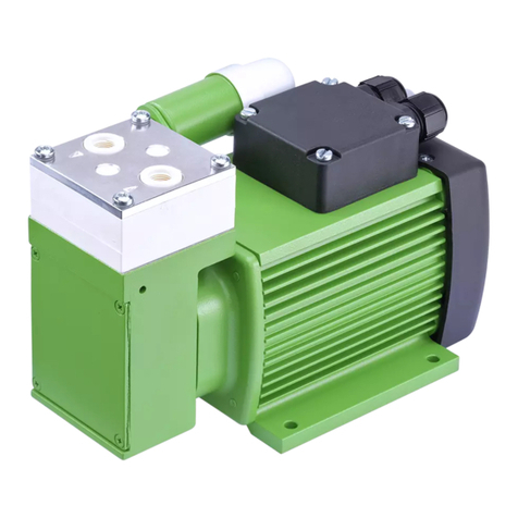
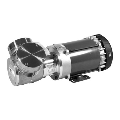
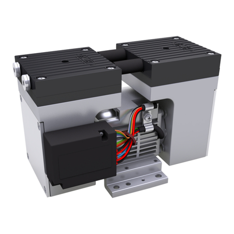
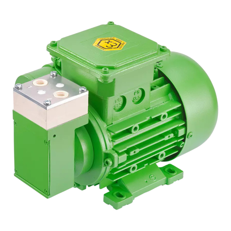
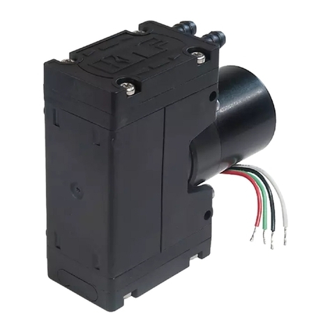
KNF UN86AT.16I User manual

Operating and Installation Instructions
Diaphragm
Vacuum Pumps and
Compressors
Type range: UN86AT.16I
UN86ST.16I
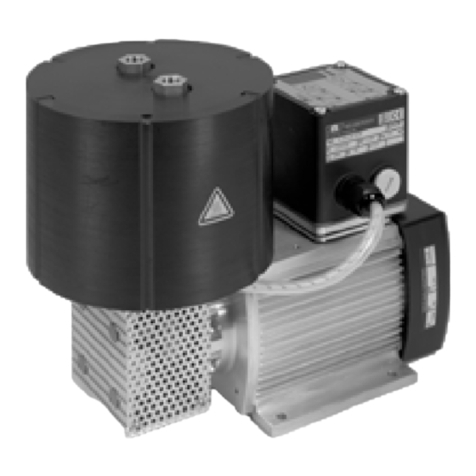
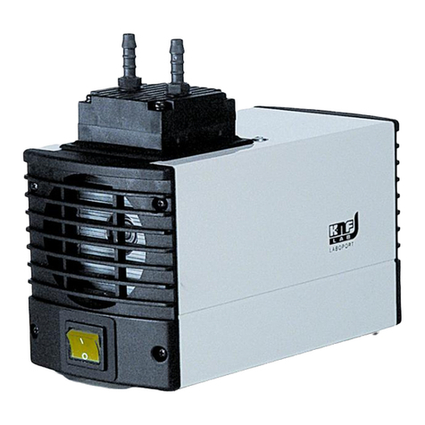
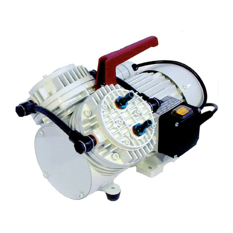
Fig. 1: UN86AT.16I with IP 00-Motor
You have selected a high-quality KNF product; the following tips will help you operate it safely and reliably
over a long period of time. Carefully study the Operating and Installation Instructions before using the
pumps and observe at all times the relevant instructions to avoid dangerous situations. The manual was
produced for the serial pumps stated above. With customer-specified projects (pump types starting with
“PU“ or “MPU“) there could be differences in detail. For customer-specified projects please therefore take
into account any agreed technical specifications, as well as these instructions.
List of Contents Page
1.
Description, Operating Conditions............................................ 2
2.
Safety ....................................................................................... 3
3.
Installation ................................................................................ 5
4.
Operation.................................................................................. 6
5.
Servicing................................................................................... 8
6.
Cleaning ................................................................................. 11
7.
Trouble Shooting .................................................................... 12
8.
Replacement parts ................................................................. 13
9.
Accessoires ............................................................................ 13
10.
Tables..................................................................................... 14
11.
Product Return ....................................................................... 15
KNF Neuberger, Inc
2 Black Forest Rd
Trenton, NJ 08691-1810
Phone: 609-890-8600
Fax: 609-890-8323
www.knf.com/usa.htm
Ident#121260-211596
Revision (11/13)

Description, Operating Conditions Diaphragm Vacuum Pumps UN86_.16I
2
1. Description, Operating Conditions
KNF pumps in the N 086.16 range transfer, evacuate and
compress 100% oil-free. In operation they are gas-tight (leak rate:
6 x 10
-3
mbar x l/sec), and maintenance-free.
They have temperature-resistant pump heads for media
temperatures up to 240 °C.
1.1. Electrical Equipment
See the type-plate for full electrical data of the motor.
The protection class of standard version is IP00.
1.2. Operating Conditions
Handling air, gases, and vapours at temperatures between
+ 5 °C … + 240 °C.
For maximum permissible operating pressure, ultimate vacuum,
and flow capacity see section 10.
The pumps must not be used in areas where there is a danger of
explosion.
Before pumping a medium, the compatibility of materials of pump
head, diaphragm and valves with the medium must be checked (for
pump materials: see section 10).
These pumps must not be used for liquids. You will find suitable
liquid pumps in our Product Program.
If your potential application lies outside the above limits discuss it
with our technical adviser (see last page for contact telephone
number).
1.3. Ambient Conditions
When the pump is operating the following ambient conditions must
be maintained:
Ambient temperature during operation: between + 5 °C …
+ 40 °C.
The pumps must be protected from the effects of dust and
water.
The pumps must not be used in areas where there is a
danger of explosion.
During operation an adequate supply of air for cooling
must be provided.
1.4. Pump materials
See section 10.

Diaphragm Vacuum Pumps UN86_.16I Safety
3
2. Safety
The pumps have Protection Class 00, and so offer no
protection against contact or foreign bodies. It is therefore
essential to provide protection for persons against contact
with live parts (e.g. electrical connections, motor windings),
and moving parts (e.g. fan). Protection against the entry of
foreign bodies must also be provided.
The pump has no protection against water. In this case too, as far
as is relevant, measures to protect the pump must be taken before
putting it into service.
Note that the pumps may only be used for their intended purpose.
The pumps must not be used in areas where there is a danger of
explosion.
For vacuum pumps, the exhaust gases must be safely disposed.
Components connected to the pump must be designed to
withstand the pneumatic performance of the pump.
Take care that safety regulations are observed when connecting
the pump to the electricity supply.
For pumps with thermal switch: When the operation of the pump is
interrupted by the thermal switch, the pump will re-start
automatically after cooling down. Take all care necessary to
prevent this leading to a dangerous situation.
Specific safety instructions for the media being handled must be
observed.
When using hot media, the pneumatic pump suction and pressure
lines heat up, as does the pump head. Do not touch these parts;
they could burn you.
Use only original KNF spare parts.
For the purposes of the Machinery Directive 2006/42/EC, pumps
are “partly completed machinery,” and are therefore to be regarded
as not ready for use. Partly completed machinery may not be
commissioned until such time as it has been determined that the
machine in which the partly completed machinery is to be
assembled is in conformity with the provisions of the Machinery
Directive 2006/42/EC. The following essential requirements of
Annex I of Directive 2006/42/EC (general principles) are applied
and observed:
General Principles No. 1
No. 1.1.3 / 1.1.3 /1.3.1 / 1.3.4 / 1.4.1 / 1.5.1 / 1.5.2 / 1.5.8 /
1.5.9 / 1.7.4 / 1.7.4.1 / 1.7.4.3
As these partly completed machinery are OEM-models the power
supplies and the equipment for disconnecting and switching-off the
partly completed machinery respectively have to be considered
when mounting as well as over-current and overload protective
gear.
EC Directives / Standards

Safety Diaphragm Vacuum Pumps UN86_.16I
4
In addition a protection against mechanical parts in motion and hot
parts, if existing, has to be provided when mounting.
The pumps conform to the EC Directive 201/65/EU (RoHS2).
The pumps conform to the EC Directive 2004/108/EC concerning
Electromagnetic Compatibility.
The following harmonized standards have been used:
DIN EN 55014-1/2
DIN EN 61000-3-2/3
DIN EN 60335-1

Diaphragm Vacuum Pumps UN86_.16I Installation
5
3. Installation
The pumps are OEM models intended for installation in equipment.
When installing them make certain that accident prevention
regulations, and safety instructions, including those for subsequent
operation are observed. The safety instructions in section 2 must
be observed.
The dimensions of the mountings are given in the Data Sheet.
Install the pump so that the fan can draw in sufficient cooling air.
Install the pump so as accidental finger contact is with the fan is
impossible.
Fit the pump at the highest point in the system, so that condensate
cannot collect in the head of the pump - that prolongs working life.
When making the electrical installation the safety regulations
must be observed. In particular make sure that the electricity
supply is isolated before trying to connect the pump.
Compare the supply data with the data on the motor-plate. The
voltage must not vary by more than +6% and -10% from that
shown on the type-plate.
The earth (ground) wire must be connected to the motor.
In the electrical installation, arrangements (complying with EN
60335-1) must be made for disconnecting the pump motor from the
electrical supply.
The pump must be installed so that contact with live parts (e.g.
electrical connection) is impossible.
We recommend that a fuse is installed in the supply circuit; the
operating current is given in Data Sheet.
Remove the protection plugs from the port threads.
Connect the suction and pressure lines (for size of the port threads
see section 10). For flow direction see marking on the pump head
or data sheet.
Arrange the suction and pressure lines so that condensate cannot
run into the pump (sloping lines).
Mechanical
Electrical
Pneumatic

Operation Diaphragm Vacuum Pumps UN86_.16I
6
4. Operation
The pumps must not be used in areas where there is a danger of
explosion.
Specific safety instructions for the media being handled must be
observed.
If combustible media are used:
Hazard of fires and explosions due to excessively high
media temperature.
Be aware that the pumps are not designed to be
explosion-proof.
Make sure the temperature of the medium is always
sufficiently below the ignition temperature of the medium,
to avoid ignition or explosion. This also applies for unusual
operational situations.
Note that the temperature of the medium increases when
the pump compresses the medium.
Hence, make sure the temperature of the medium is
sufficiently below the ignition temperature of the medium,
even when it is compressed to the maximum permissible
operating pressure of the pump.
The maximum permissible operating pressure of the pump
is stated in the technical specifications (section 10).
If necessary, consider any external sources of energy,
such as radiation, that may add heat to the medium.
In case of doubt, consult the KNF customer service.
Before pumping a medium, the compatibility if material of pump
head, diaphragm and valves with the medium must be checked (for
pump material: see section 10).
The pump must not start against pressure or vacuum. When it is
switched on the pressure in the suction and pressure lines must be
atmospheric. This must be so even when the pump restarts after
the power has been cut off for a short period.
The maximum permissible operating pressure (see section 10)
must not be exceeded.
To prevent the maximum permissible operating pressure being
exceeded, restriction or control of the air or gas flow should only be
carried out in the suction line.
If restriction or control of the air or gas flow is made on the pres-
sure side ensure that the maximum permissible operating pressure
is not exceeded.
When the pump is at a standstill the inlet and outlet must be at
normal atmospheric pressure.
The pumps must not be used to produce vacuum and pressure at
the same time.

Diaphragm Vacuum Pumps UN86_.16I Operation
7
For pumps with a thermal switch: When the operation of the pump
is interrupted by the thermal switch, the pump will re-start
automatically after cooling down. Take all care necessary to
prevent this leading to a dangerous situation.
Diaphragm and valve plate are the only parts subject to wear.
Wear is usually indicated by a drastic reduction in the pneumatic
performance. When replacing parts proceed as described in
section 5.
Ambient conditions: see section 1.3.

Servicing Diaphragm Vacuum Pumps UN86_.16I
8
5. Servicing
Before working on the pump, isolate the power supply
securely, then check that the lines are not live.
Diaphragm and valve plate are the only parts of the pump subject
to wear. They are simple to change.
Always change diaphragm, valve plate and sealing ring at the
same time. If diaphragm and valve plate are not changed at the
same time the nominal performance of the pump is not guaranteed
after the service.
If aggressive, toxic or other types of gases hazardous to health
have been pumped please observe:
1. Clean the pump and its components before servicing.
2. Ensure that the service personnel is not subject to a health
hazard during diaphragm and valve plate changes. Apply the
necessary safety measures (example: the use of protective
gloves).
3. Ensure that the discarded parts and materials are safely and
correctly disposed of.
After opening the pump head, or replacing the diaphragm and
valve plate the initial gas-tightness is no longer guaranteed. A leak
test is able to verify that the original standard of gas-tightness has
been achieved.
Spare part* Quantity
Valve plate 1
Wave diaphragm (assembly
consisting of two equivalent parts)
1
O-ring 1
Tab. 1 * According to Spare parts list, section 8
Tools/Material
Fork wrench or socket wrench 5.5 mm
Pin-wrench for two hole nuts, pin diameter 4 mm (available as
“wrench for retainer plate”, a KNF accessory, see section 9)
Holding tool (see accessories, section 9)
Heat-resistant thread adhesive (e.g. DELO ML 5327)
Felt-tip pen
Tab. 2
Change the structured diaphragm and valve plate in the following
sequence:
a) Preparatory step
b) Removing pump head
Parts required
Tools/material required

Diaphragm Vacuum Pumps UN86_.16I Servicing
9
c) Changing diaphragm
d) Changing valve plate and sealing ring
e) Refitting pump head
f) Final step
Fig. 3: Pump head (exploded drawing)
Fig. 2: UN86.16AT.16I
Fig. 4: Orientation of disk springs (5)
Specification
Pos. Description
1 Carrier
2 Wave diaphragm
3 Intermediate plate
4 Head plate
5 Disk spring
6 Nut
7 Retainer plate
8 Diaphragm support
9 Connecting rod extension
10 O-ring
11 Valve plate
12 Washer
13 Fan
MMark

Servicing Diaphragm Vacuum Pumps UN86_.16I
10
The item numbers in the following instructions refer to figs. 2 to 4.
Proceed as follows:
a) Preparatory step
1. Disconnect the pump from the power supply; check that the
pump is electrically dead and secure this.
b) Removing pump head
1. Mark the position of carrier (1), intermediate plate (3), and
head plate (4) relative to each other by a drawing line (M) with
a felt-tip marker. This is to ensure that the parts will be
reassembled in correct position at a later stage.
2. Release the nuts (6) and remove them together with the disk
springs (5).
The disk springs are fitted in order to maintain the tension of
the wave diaphragm right across the temperature range of the
pump.
3. Remove head plate (4).
4. Remove O-ring (10) from head plate (4).
5. Remove the valve plate (11) and the intermediate plate (3).
c) Changing diaphragm
1. Release the retainer plate (7) by turning it anti-clockwise with a
pin wrench or a wrench for retainer plate. While doing so, hold
the connecting rod extension (9) in place with holding tool.
Take care to ensure that the washer (12) does not slip under
the diaphragm support (8)
2. Remove wave diaphragm (2).
3. Check that all parts are free from dirt and clean them if
necessary (see section 6. Cleaning).
4. Slide a new wave diaphragm (2) onto the threaded bolt of the
retainer plate (7).
The wave diaphragm assembly consists of two equivalent
parts placed on top of one another; the top and bottom are
identical.
5. Apply a small amount of heat-resistant thread adhesive (e.g.,
DELO ML 5327) to the thread of the retainer plate (7).
6. Screw the retainer plate (7) with wave diaphragm (2) into the
connecting rod extension (9); to tighten the retainer plate, use
the wrench for retainer plate/the pin wrench to turn it clockwise
(torque: 4.6 Nm). While doing so, hold the connecting rod
extension (9) in place with the holding tool; and hold the wave
diaphragms so that they do not twist.

Diaphragm Vacuum Pumps UN86_.16I Cleaning
11
d) Changing valve plate and sealing
1. Check that intermediate plate and head plate are clean. If
damages, distortion, or corrosion are evident on these parts
they should be replaced.
2. Place the intermediate plate (3) on the carrier (1) in the
position indicated by the felt tip pen mark (M).
3. Lay the new valve plate (11) onto the intermediate plate (3).
Regarding the placement of the vale plate:
The notch on outer edge of the valve plate must be at the left
rear, when looking at the pump from the motor.
4. Fit the new O-ring (10) in the head plate (4).
e) Refitting pump head
1. Place the head plate (4) on the intermediate plate (3) in the
position indicated by the felt-tip pen marking.
2. Place disk springs (5).
For position see fig. 4.
3. Put the nuts (6) in place and tighten them diagonally, until
each of them lies level on the top spring washer; realign the
pump head.
From when you start applying pressure on the disk springs,
tighten the nuts through an angle of 340 °. That is equivalent to
a torque of 80 Ncm.
f) Final step
1. Reconnect the pump to the electricity supply.
If you have any questions about servicing call our technical adviser
(see last page for contact telephone number).
6. Cleaning
When changing valve plate and wave diaphragm, inspect all parts
for dirt before assembling the pump head, and clean them if
necessary.
If a compressed air line is available, blow the parts out with it.

Trouble Shooting Diaphragm Vacuum Pumps UN86_.16I
12
7. Trouble Shooting
Before working on the pump isolate the power supply
securely, then check that the lines are not live.
The following tips for fault-finding are best employed in the
sequence shown.
Pump produces no flow
Pumps with thermal switch: The thermal switch has
opened due to over-heating.
Disconnect pump from mains and allow to cool.
Trace cause of over-heating and eliminate it.
Connections or lines are blocked
An external valve is closed, or a filter blocked.
Liquid (condensate) has collected in the pump head.
Let the pump run for a few minutes pumping air (if
necessary for safety reasons: pumping an inert
gas.)
Install the pump at the highest point in the system.
Diaphragm or valve plate is worn.
Section 5 Servicing.
Flow, pressure, or vacuum too low
Compare the actual performance with the figures in section
10 or the data sheet.
There is pressure on the pressure side, and at the same
time vacuum, or a pressure above atmospheric, on the
suction side.
The pump is not designed for this condition.
Liquid (condensate) has collected in the pump head.
Let the pump run for a few minutes pumping air (if
necessary for safety reasons: pumping an inert
gas.)
Install the pump at the highest point in the system.
The cross-section of pneumatic lines, or connected
components is too small, or they are restricted.
To measure the performance, disconnect the
pump from the system (small diameter tubing or a
valve can significantly affect performance).
There is a leak at a connector, in a line, or in the pump
head.
Diaphragm or valve plate is worn, or dirt is in the head:
Section 5 Servicing.

Diaphragm Vacuum Pumps UN86_.16I Replacement parts
13
If the pump does not operate properly and you cannot find any of
the above faults, send it to the KNF Service Department.
In order for KNF to repair the pump, the customer must provide a
statement on the media which were pumped and on pump
cleaning. Please fill out the corresponding KNF form, and submit it
together with the pump. A sample statement for copying can be
found in section 11 of these operating instructions.
8. Replacement parts
Spare part Order-No.
Valve plate 006066
Wave diaphragm 012074
O-Ring 052713
Disk spring 005205
Tab. 3: Replacement parts
9. Accessoires
Accessory Order-No.
Wrench for retainer plate 018812
Holding tool 055662
Tab. 4: Accessoires

Tables Diaphragm Vacuum Pumps UN86_.16I
14
10. Tables
Pump type Max. permissible
operating pres-
sure (bar g)
Ultimate
vacuum
(mbar abs.)
Delivery rate*
(l/min) at atm.
pressure
UN86AT.16I 1.5 290 6
UN86ST.16I 1.5 290 6
Tab. 5: Pneumatic Data *Liter at STP
Pump type
Material*
Pump head Wave diaphragm Valve plate
UN86AT.16I Aluminium alloy PTFE PTFE
UN86ST.16I Stainless steel PTFE PTFE
Tab. 6: Pump materials
Pump type Thread size
UN86AT.16I I/8” NPT
UN86ST.16I I/8” NPT
Tab. 7: Size of pneumatic port threads

Diaphragm Vacuum Pumps UN86_.16I Product Return
15
11. Product Return
KNF provides warranty and non-warranty repair services for all
products.
A Return Material Authorization (RMA) number is required for
all product returns.
•To receive an RMA number, submit a completed
The Decontamination Declaration form can obtained from our
website or by contacting KNF Technical Services.
•http://www.knf.com/pdfs/decontamdec.doc
•Phone: 609-890-8600
Product return instructions will be provided when the RMA is
issued.
KNF Neuberger, Inc
2 Black Forest Rd
Trenton, NJ 08691-1810
Phone 609-890-8600
Fax 609-890-8323
www.knf.com/usa.htm

KNF worldwide
Benelux
Netherlands
KNF Verder B.V.
Utrechtseweg 4a
NL-3451 GG Vleuten
Tel. 0031 (0)30 677 92 40
Fax 0031 (0)30 677 92 47
E-mail: info@knf-verder.nl
www.knf-verder.nl
Benelux
Belgium, Luxembourg
KNF Verder N.V.
Kontichsesteenweg 17
B-2630 Aartselaar
Tel. 0032 (0)3 8719624
Fax 0032 (0)3 8719628
E-mail: info@knf.be
www.knf.be
China
KNF Neuberger Trading
(Shanghai) Co., Ltd
No. 36 Lane 1000
Zhang Heng Road
Shanghai 201203, P.R. China
Tel. 0086 (0)21 685 965 66
Fax 0086 (0)21 339 006 26
E-mail: info@knf.com.cn
www.knf.com.cn
Germany
KNF Neuberger GmbH
Alter Weg 3 D-79112 Freiburg
Tel. 0049 (0)7664 5909-0
Fax 0049 (0)7664 5909-99
E-mail: info@knf.de
www.knf.de
France, Morocco,
Algeria
KNF Neuberger
4, Bld. d’Alsace Z.I.
F-68128 Village-Neuf
Tel. 0033 (0)389 70 35 00
Fax 0033 (0)389 69 92 52
E-mail: info@knf.fr
www.knf.fr
Great Britain
KNF Neuberger U.K. Ltd.
Avenue 2
Station Lane
Industrial Estate
Witney Oxon OX28 4FA
Tel. 0044 (0)1993 77 83 73
Fax 0044 (0)1993 77 51 48
E-mail: info@knf.co.uk
www.knf.co.uk
India
KNF Pumps + Systems
(India) Pvt. Ltd.
RAJIV GANDHI INFOTECH PARK
Phase 1
Ganga Estate, Survey No. 152/2/2
Above AXIS BANK
Hinjewadi
Pune 411 057
Tel. 0091 (0)20 640 13 923
0091 (0)20 640 08 923
Fax 0091 (0)20 229 33 923
E-mail: info@knfpumps.in
www.knfpumps.in
Italy
KNF ITALIA S.r.l.
Via Flumendosa, 10
I-20132 Milano
Tel. 0039 02 27 20 38 60
Fax 0039 02 27 20 38 48
E-mail: info@knf.it
www.knf.it
Japan
KNF Japan Co.Ltd.
Chichibu, Bldg. 7F
1-8-6 Shinkawa, Chuo-ku,
Tokyo, Japan 104-0033
Tel. 0081 (0)3 3551-7931
Fax 0081 (0)3 3551-7932
E-mail: info@knf.co.jp
www.knf.co.jp
Korea
KNF Neuberger Ltd.
Woosan Bldg.RM#202,
336-4, Hwikyung-Dong
Dongdaemun-Ku.,
130-090, Seoul
Tel. 0082 (0)2 959-0255/6
Fax 0082 (0)2 959-0254
E-mail: knf@knfkorea.com
www.knfkorea.com
Sweden, Denmark,
Finland, Norway
KNF Neuberger AB
Mejerivägen 4,
P.O. Box 44060
SE-10073 Stockholm
Tel. 0046 (0) 87445113
Fax 0046 (0) 87445117
E-mail: [email protected]
www.knf.se
Switzerland
Sales
KNF Neuberger AG
Stockenstrasse 6
CH-8362 Bichelsee-Balterswil
Tel. 0041 (0)71 973 993 0
Fax 0041 (0)71 973 993 1
E-mail: [email protected]
www.knf.ch
Taiwan
KNF Neuberger Ltd.
9-2 FL., No., 24, Lane 123,
Section 6,
Ming Chuan East Road
Taipei City, Taiwan
Tel. 00886-2-2794-1011
Fax 00886-2-8792-1648
E-mail: knftwn@knftwn.com.tw
www.knftwn.com.tw
USA, Canada, South America
KNF NEUBERGER, INC.
Two Black Forest Road
Trenton, New Jersey
08691-1810
Tel. 001 (609) 890 86 00
Fax 001 (609) 890 83 23
E-mail: [email protected]
www.knf.com/usa.htm
South America
Direct Phone: 001 609 649 1010
E-mail: [email protected]
KNF product ce
ntres
Product centre for gas
pumps:
Germany
KNF Neuberger GmbH
Alter Weg 3
D-79112 Freiburg
Phone 0049(0)7664 5909-0
Fax 0049(0)7664 5909-99
E-mail: info@knf.de
www.knf.de
Product centre for fluid
pumps:
Switzerland
KNF FLODOS AG
Wassermatte 2
CH-6210 Sursee
Phone 0041(0)41 925 00 25
Fax 0041(0)41 925 00 35
E-mail: info@knf-flodos.ch
www.knf-flodos.ch
Product centre for micro
pumps:
Switzerland
KNF Micro AG
Zelglimatte 1b
CH-6260 Reiden
Tel. 0041(0)62 787 88 88
Fax 0041(0)62 787 88 99
E-mail: info@knf-micro.ch
www.knf-micro.ch
This manual suits for next models
1
Table of contents
Other KNF Water Pump manuals
Popular Water Pump manuals by other brands

GORMAN-RUPP PUMPS
GORMAN-RUPP PUMPS 02K11-X2 1P Installation, operation, and maintenance manual with parts list

EINHELL
EINHELL ROYAL HW 1300 Niro/Niro operating instructions

Koshin
Koshin PKG-1500 Operation manual

BTS
BTS BEDJ manual

webtrol
webtrol WTE Series Installation & operating manual

NEPTUN classic
NEPTUN classic NCGP-E 70 Original operating instructions

AquaCare
AquaCare BasiTech instruction manual

Hyundai power products
Hyundai power products HY50-A-1 Original instructions

POMPE ROTOMEC
POMPE ROTOMEC TR Series Use and maintenance manual

WilTec
WilTec 62138 Operation manual

MATO
MATO CMiNDTEK EP 100 operating instructions

YUKEN KOGYO
YUKEN KOGYO ASE Series instruction manual