KNF LABOPORT N 810 FT.18 Wiring diagram

Note!
Before operating the pump and the accessories, please read the operating instructions on the web site
(www.knf.com/downloads) and pay attention to the safety precautions!
KNF 309515-309518 12/16
LAB
N 810/820/840.18 EX
TRANSLATION OF ORIGINAL-OPERATING
INSTRUCTIONS
ENGLISH
LABOPORT®
CHEMICALLY-RESISTANT
LABORATORY PUMPS

Content Page
1. About this document 3
1.1. Using the Operating Instructions 3
1.2. Symbols and Markings 3
2. Use 4
2.1. Proper Use 4
2.2. Improper Use 4
2.3. Use to transfer explosive atmospheres 5
2.4. Explanations of the explosion protection marking 6
2.4.1.Device groups 6
2.4.2.Device categories for gas 6
2.4.3.Explosion groups 7
2.4.4.Temperature classes 8
2.4.5.Additional conditions 8
3. Information about EX marking 9
4. Safety 10
5. Technical Data 12
6. Design and Function 19
7. Installation, mounting and connection 21
8. Operation 23
8.1. Pump 23
8.1.1.Preparing for Start-up 23
8.1.2.Starting 23
8.2. Switching Pump on and off 25
9. Servicing 26
9.1. Servicing Schedule 26
9.2. Cleaning 26
9.2.1.Flushing Pump 26
9.2.2.Cleaning Pump 26
9.3. Changing Diaphragm and Valve Plates/Sealings 27
10. Troubleshooting 31
10.1. Pump without Vacuum Controller 31
10.2. Fault cannot be rectified 32
11. Ordering Information 33
11.1. Pumps and Spare Parts 33
11.2. Head plates and intermediate plates 33
12. Returns 34
13. Health and safety clearance and decontamination form35
KNF Neuberger GmbH
Alter Weg 3
D-79112 Freiburg
Germany
Phone ++49 / (0)7664 / 5909-0
Fax++49 / (0)7664 / 5909-99
E-Mail: info@knf.de
www.knf.de

N 810/820/840.18 EX About this document
Translation of original Operating Instructions, English, KNF 309515-309518 06/17 3
1. About this document
1.1. Using the Operating Instructions
The Operating Instructions are part of the pump.
Carefully study the Operating Instructions before using a
pump.
Always keep the Operating Instructions handy in the work
area.
Pass on the Operating Instructions to the next owner.
Customer-specific project pumps (pump models which begin with
“PJ” or “PM”) may differ from the Operating Instructions.
For project pumps, also observe the agreed upon specifications.
1.2. Symbols and Markings
Warning
WARNING
A danger warning is located here.
Possible consequences of a failure to observe the
warning are specified here. The signal word, e.g.
Warning, indicates the danger level.
Measures for avoiding the danger and its conse-
quences are specified here.
Danger levels
Signal word
Meaning
Consequences if not observed
DANGER
warns of immedi-
ate danger
Death or serious injuries
and/or serious damage are the
consequence.
WARNING
warns of possible
danger
Death or serious injuries
and/or serious damage are
possible.
CAUTION
warns of a possibly
dangerous situa-
tion
Minor injuries or damage are
possible.
Tab. 1
Other information and symbols
An activity to be carried out (a step) is specified here.
1. The first step of an activity to be carried out is specified here.
Additional, consecutively numbered steps follow.
This symbol refers to important information.
Project pumps

Use N 810/820/840.18 EX
4 Translation of original Operating Instructions, English, KNF 309515-309518 06/17
2. Use
2.1. Proper Use
The pump is exclusively intended for transferring gases and va-
pors.
Owner's responsibility
Only install and operate the pump under the operating parameters
and conditions described in chapter 5, Technical data.
Make sure that the installation location is dry and the pump is
protected against rain, splash, hose and drip water.
The pump is suitable for transferring explosive atmospheres in
explosion group IIB+H2.
The pump must not be operated in potentially explosive areas. The
Ex marking applies only to the working chamber (area in contact
with medium).
Before using a medium, check the compatibility of the materials of
the pump head, diaphragm and valves with the medium.
Before using a medium, check whether the medium can be trans-
ferred danger-free in the specific application case.
Ensure that the system is not subject to any risks of explosion, also
in extreme operating situations (temperature, pressure) or in case
of malfunctions.
Only transfer gases which remain stable under the pressures and
temperatures occurring in the pump.
Laboratory equipment or additional components connected to a
pump have to be suitable for use with the pneumatic capabilities of
the pump (see chapter 5, page 12).
2.2. Improper Use
The pump may not be operated in an explosive atmosphere.
The pump is not suitable for use underground.
The pump is not suitable for use in potentially explosive areas.
The pump is not suitable for transferring dusts.
The pump is not suitable for transferring liquids.
The pump must not be used to create vacuum and overpressure
simultaneously.
An overpressure must not be applied to the suction side of the
pump.
The pump must not be used if the gas ballast could result in the
reation of reactive, explosive or otherwise hazardous mixtures (e.g.
with the medium).
Operating parameters and
conditions
Requirements for
transferred medium
Accessories

N 810/820/840.18 EX Use
Translation of original Operating Instructions, English, KNF 309515-309518 06/17 5
2.3. Use to transfer explosive atmospheres
To transfer explosive atmospheres, use only pumps in the corre-
sponding device category and temperature class.
These pumps have the following explosion protection marking:
Marking
Description
Symbol for explosion-proof pumps
II
Device group (see Section 2.4.1).
2 G
Device category (see Section 2.4.2).
IIB+ H2
Explosion groups (see Section 2.4)
T3
Temperature class (see Section 2.4.4)
X internal
atmosphere only
Special conditions (see Section 2.4.5).
Tab. 2
The explosion protection marking can also be found at the follow-
ing location:
Type plate of the pump

Use N 810/820/840.18 EX
6 Translation of original Operating Instructions, English, KNF 309515-309518 06/17
2.4. Explanations of the explosion protection
marking
2.4.1. Device groups
Device group I applies to devices used in the underground and
above-ground operations of mines where there is a risk of methane
and/or flammable dusts.
Device group II applies to devices used in other areas where there
is a risk of explosive atmospheres.
2.4.2. Device categories for gas
The device category describes the frequency and duration of the
occurrence of an explosive atmosphere in the operations.
Device cate-
gory
Description*
1 G
Devices for areas in which it is expected that dangerous, explosive
atmospheres (gases and vapors) occur constantly, over long periods,
or frequently.
1 D
Devices for areas in which it is expected that dangerous, explosive
atmospheres (dusts) occur constantly, over long periods, or frequent-
ly.
2 G
Devices for areas in which it is expected that dangerous, explosive
atmospheres (gases and vapors) occur occasionally.
2 D
Devices for areas in which it is expected that dangerous, explosive
atmospheres (dusts) occur occasionally.
3 G
Devices for areas in which it is not expected that dangerous, explo-
sive atmospheres (gases and vapors) will occur. If, however, they do
occur, then only rarely and for short periods.
3 D
Devices for areas in which it is not expected that dangerous, explo-
sive atmospheres (dusts) will occur. If, however, they do occur, then
only rarely and for short periods.
Tab. 3 * according to DIN EN 13463-1
Device group I
Device group II

N 810/820/840.18 EX Use
Translation of original Operating Instructions, English, KNF 309515-309518 06/17 7
2.4.3. Explosion groups
Flammable gases and vapors are classified according to explosion
groups (I, IIA, IIB, and IIC) and temperature classes. Tab. 4 shows
the classification of the most common flammable gases and va-
pors.
T1
T2
T3
T4
T5
T6
I
Methane
–
–
–
–
–
IIA
Acetone
Ethane
Ethyl acetate
Ammonia
Ethyl chloride
Benzene
Acetic acid
Carbon monoxide
Methane
Methanol
Methyl chloride
Naphthalene
Phenol
Propane
Toluene
i-Amyl acetate
n-Butane
n-Butanol
Cyclohexanone
1,2-dichloroethane
Acetic anhydride
Gasoline
Diesel fuel
Jet fuel
Fuel oils
n-Hexane
Acetaldehyde
–
–
IIB
Town gas
Ethylene
Ethyl alcohol
Hydrogen
sulfide
Diethyl ether
–
–
IIC
Hydrogen
Acetylene
–
–
–
Carbon
disulfide
Tab. 4
The classification of gases and vapors into explosion groups and
temperature classes applies to the transferred medium.
The pump may be used only to transfer gases and vapors in ex-
plosion groups IIA or IIB+ H2 and temperature class T3 (and lower)
(marked area in Tab. 4) or that are not flammable.
The pump must not be installed in potentially explosive areas. It is
suitable only to transfer explosive atmospheres.
Transferred medium
Pump environment

Use N 810/820/840.18 EX
8 Translation of original Operating Instructions, English, KNF 309515-309518 06/17
2.4.4. Temperature classes
The maximum surface temperature is the highest temperature that
the surface of a pump reaches under the least favorable condi-
tions.
The maximum surface temperature of the pump must always be
lower than the lowest ignition temperature of the gas or vapor/air
mixture in which it is used.
The maximum surface temperature is based on the design of the
pump and is specified as temperature class.
Temperature class
Max. surface tem-
perature [°C]
Ignition temperature
[°C]
T1
450
> 450
T2
300
> 300
T3
200
> 200
T4
135
> 135
T5
100
> 100
T6
85
> 85
Tab. 5
2.4.5. Additional conditions
Marking
Description
X internal at-
mosphere only
Special additional conditions
Tab. 6
Additional conditions for the diaphragm pump:
The pump must not be installed outdoors. It may be started up
only with suitable weatherproof and corrosion protection clad-
ding.
The pump must not be installed in potentially explosive areas.
It is suitable only to transfer explosive atmospheres.
The pump must be installed so that it cannot be damaged
externally.
Maximum
surface temperature
Ignition temperature
Temperature class

N 810/820/840.18 EX Information about EX marking
Translation of original Operating Instructions, English, KNF 309515-309518 06/17 9
3. Information about EX marking
This KNF pump, type:
N 810FT.18 N 810.3FT.18 N 810.3FT.18G
N 820FT.18 N 820.3FT.18 N 820.3FT.18G
N 840FT.18 N 840.3FT.18 N 840.3FT.18G
N 840.1.2FT.18
has the following device marking according to the latest explosion
prevention and protection directive. The marking applies only to the
working chamber of the pump (area in contact with medium).
Fig. 1: EX marking of the pumps
Vacuum pumps in category 2G are designed to transfer gases,
vapors, or aerosols where it is expected that an explosive atmos-
phere will form occasionally.
The devices must be installed so that they cannot suffer external
mechanical damage.
The pumps must not be modified. If a wearing part is replaced, the
original function of the pump must be checked by reaching the
specified ultimate vacuum (see Operating Instructions, Servicing).

Safety N 810/820/840.18 EX
10 Translation of original Operating Instructions, English, KNF 309515-309518 06/17
4. Safety
Note the safety precautions in chapters 7. Installation, mount-
ing and connection,
and 8. Operation.
The pump is built according to the generally recognized rules of
technology and in accordance with the occupational safety and
accident prevention regulations. Nevertheless, dangers can result
during their use which lead to injuries to the user or others, or to
damage to the pump or other property.
Only use the pump when it is in a good technical and proper work-
ing order, in accordance with its intended use, observing the safety
advice within the operating instructions, at all times.
Make sure that only trained and instructed personnel or specially
trained personnel work on the pump. This especially applies to
assembly, connection and servicing work.
Make sure that the personnel has read and understood the operat-
ing instructions, and in particular the "Safety" chapter.
Observe the accident prevention and safety regulations when
performing any work on the pump and during operation.
Do not expose any part of your body to the vacuum.
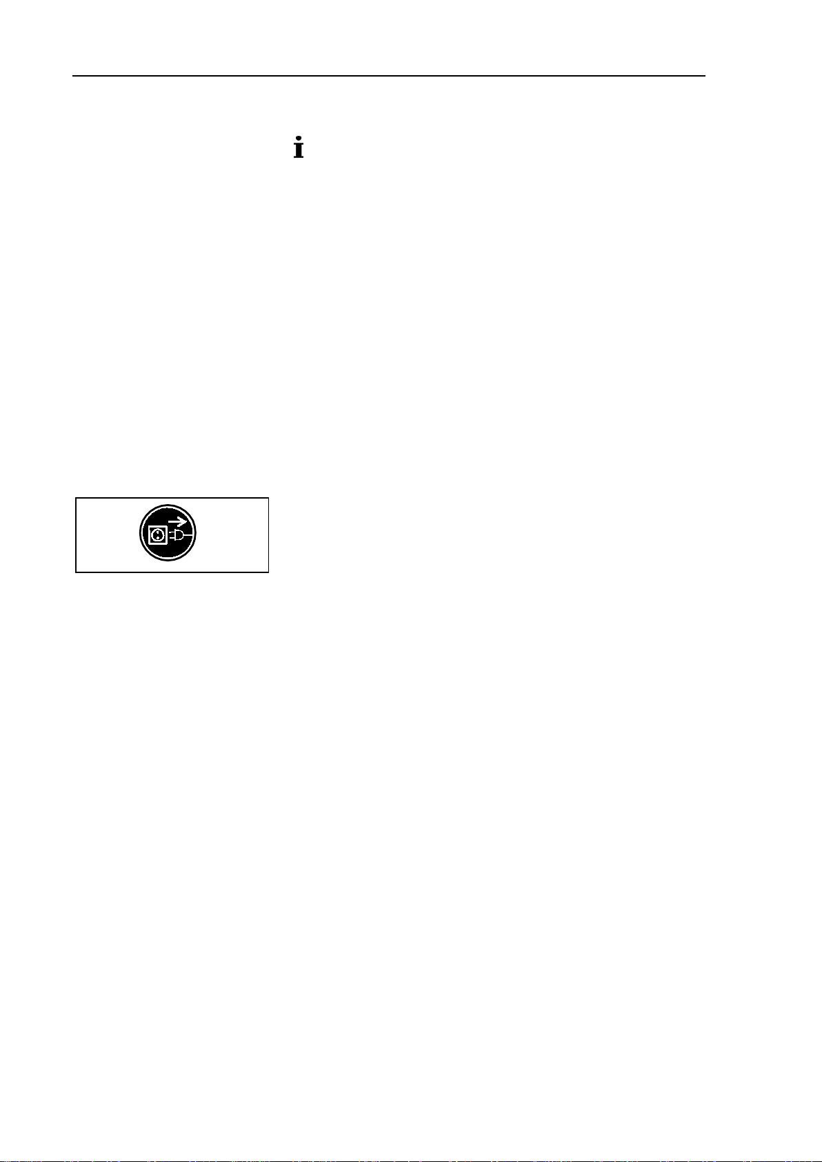
Open housing parts with notice sticker (see Fig. 2) only after
separating mains plug from power source.
When transferring dangerous media, observe the safety regula-
tions when handling these media.
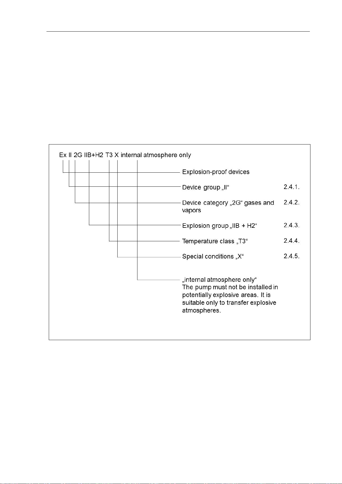
Remember that the pump is suitable only for transferring explosive
atmospheres and may not be installed in potentially explosive
areas.
Make sure the temperature of the medium is always sufficiently
below the ignition temperature of the medium, to avoid ignition or
explosion. This also applies for unusual operational situations.
Note that the temperature of the medium increases when the pump
compresses the medium.
Hence, make sure the temperature of the medium is sufficiently
below the ignition temperature of the medium, even when it is
compressed to the maximum permissible operating pressure of the
pump. The maximum permissible operating pressure of the pump
is stated in the technical specifications (see chapter 5, page 12).
If necessary, consider any external sources of energy, such as
radiation, that may add heat to the medium.
In case of doubt, consult the KNF customer service.
Store all replacement parts in a protected manner and dispose of
them properly in accordance with the applicable environmental
protection regulations. Observe the respective national and inter-
national regulations. This especially applies to parts contaminated
with toxic substances.
Personnel
Working in a safety-
conscious manner
Fig. 2: Notice sticker
Handling dangerous media
Handling flammable media and
explosive atmospheres
Environmental protection

N 810/820/840.18 EX Safety
Translation of original Operating Instructions, English, KNF 309515-309518 06/17 11
The part of the pump that comes into contact with medium corre-
sponds to Directive 2014/34/EU (ATEX).
The pumps conform to the Directive 2011/65/EU (RoHS2).
The pumps conform to the safety regulations of the Directive
2014/30/EU concerning Electromagnetic Compatibility and the
Directive 2006/42/EC concerning Machinery. The requirements of
the following harmonised standards are fulfilled:
DIN EN 61010-1
DIN EN 61326-1 – class A
DIN EN 50581
The part of the pump that comes into contact with medium is
fulfilled by the following harmonized standards:
DIN EN 13463-1
DIN EN 1127-1
The pumps correspond to IEC 664:
the overvoltage category II
the pollution degree 2
Only have repairs to the pump carried out by the KNF Customer
Service responsible.
Only authorized personnel should open those parts of the housing
that contain live electrical parts.
Use only genuine parts from KNF for servicing work.
EC/EU directives/standards
Customer service and
repairs

Technical Data N 810/820/840.18 EX
12 Translation of original Operating Instructions, English, KNF 309515-309518 06/17
5. Technical Data
All pumps are secured against overheating with thermal
switches and are equipped with a mains fuse.
Pump materials (for all pump types)
Pump head
PTFE
Diaphragm
PTFE coated
Valve
FFPM
Connections
PVDF/PTFE
Hose connectors
PVDF
Gas ballast
only N 8_0.3FT.18G
PVDF
Tab. 7
Refer to the type plate for the pump’s electrical configuration.
N 810 FT.18
Pneumatic performance
Max. permissible operating
pressure [bar g]
1.0
Ultimate vacuum [mbar abs.]
≤100
Delivery rate at atm. pressure
[l/min]*
max. 10
Pneumatic connection
Hose connection [mm]
ID 10
Ambient and media temperature
Permissible
ambient temperature
+ 5 °C to + 40 °C
Permissible media tempera-
ture
+ 5 °C to + 40 °C
Other parameters
Weight [kg]
5.9
Dimensions: L x H x W [mm]
256 x 187 x 146
Maximum permissible ambient
relative humidity
80 % for temperatures up to
31 °C, decreasing linearly to
50 % at 40 °C
Maximum altitude of site
[m above sea level]
2000
Electrical Data
Voltage [V]
100
115
230
Frequency [Hz]
50/60
60
50
Maximum current consump-
tion [A]
1.4
1.3
0.6
Power consumption pump [W]
110
110
100
Maximum permitted mains
voltage fluctuation
+/- 10 %
+/- 10 %
+/- 10 %
Fuse pump
(2x) T [A]
2.5
2.5
1.25
Protection class motor
IP44
Tab. 8 * Liters in standard state (1,013 mbar)

N 810/820/840.18 EX Technical Data
Translation of original Operating Instructions, English, KNF 309515-309518 06/17 13
N 820 FT.18
Pneumatic performance
Max. permissible operating
pressure [bar g]
1.0
Ultimate vacuum [mbar abs.]
≤100
Delivery rate at atm. pressure
[l/min]*
max. 20
Pneumatic connection
Hose connection [mm]
ID 10
Ambient and media temperature
Permissible
ambient temperature
+ 5 °C to + 40 °C
Permissible media tempera-
ture
+ 5 °C to + 40 °C
Other parameters
Weight [kg]
7.1
Dimensions: L x H x W [mm]
268 x 207 x 159
Maximum permissible ambient
relative humidity
80 % for temperatures up to
31 °C, decreasing linearly to
50 % at 40 °C
Maximum altitude of site
[m above sea level]
2000
Electrical Data
Voltage [V]
100
115
230
Frequency [Hz]
50/60
60
50
Maximum current
consumption [A]
2.2
1.9
0.9
Power consumption pump [W]
145
145
130
Maximum permitted mains
voltage fluctuation
+/- 10 %
+/- 10 %
+/- 10 %
Fuse pump
(2x) T [A]
4.0
3.15
2.0
Protection class motor
IP44
Tab. 9 * Liters in standard state (1,013 mbar)

Technical Data N 810/820/840.18 EX
14 Translation of original Operating Instructions, English, KNF 309515-309518 06/17
N 840 FT.18
Pneumatic performance
Max. permissible operating
pressure [bar g]
1.0
Ultimate vacuum [mbar abs.]
≤100
Delivery rate at atm. pressure
[l/min]*
max. 34
Pneumatic connection
Hose connection [mm]
ID 10
Ambient and media temperature
Permissible
ambient temperature
+ 5 °C to + 40 °C
Permissible media tempera-
ture
+ 5 °C to + 40 °C
Other parameters
Weight [kg]
10.3
Dimensions: L x H x W [mm]
297x 226 x 171
Maximum permissible ambient
relative humidity
80 % for temperatures up to
31 °C, decreasing linearly to
50 % at 40 °C
Maximum altitude of site
[m above sea level]
2000
Electrical Data
Voltage [V]
100
115
230
Frequency [Hz]
50/60
60
50
Maximum current consump-
tion [A]
4.4
3.2
1.5
Power consumption pump [W]
200
220
180
Maximum permitted mains
voltage fluctuation
+/- 10 %
+/- 10 %
+/- 10 %
Fuse pump
(2x) T [A]
6.3
6.3
3.15
Protection class motor
IP44
Tab. 10 * Liters in standard state (1,013 mbar)N 810.3 FT.18

N 810/820/840.18 EX Technical Data
Translation of original Operating Instructions, English, KNF 309515-309518 06/17 15
N 810.3 FT.18 N 810.3FT.18G
Pneumatic performance
Max. permissible operating
pressure [bar g]
1.0
Ultimate vacuum [mbar abs.]
≤8 (gas ballast closed)
≤ 30 (gas ballast open)
Delivery rate at atm. pressure
[l/min]*
max. 10
Pneumatic connection
Hose connection [mm]
ID 10
Ambient and media temperature
Permissible
ambient temperature
+ 5 °C to + 40 °C
Permissible media tempera-
ture
+ 5 °C to + 40 °C
Other parameters
Weight [kg]
6.9
Dimensions: L x H x W [mm]
281 x 187 x140
Maximum permissible ambient
relative humidity
80 % for temperatures up to
31 °C, decreasing linearly to
50 % at 40 °C
Maximum altitude of site
[m above sea level]
2000
Electrical Data
Voltage [V]
100
115
230
Frequency [Hz]
50/60
60
50
Maximum current consump-
tion [A]
1.4
1.3
0.6
Power consumption pump [W]
100
110
90
Maximum permitted mains
voltage fluctuation
+/- 10 %
+/- 10 %
+/- 10 %
Fuse pump
(2x) T [A]
2.5
2.5
1.25
Protection class motor
IP44
Tab. 11 *Liters in standard state (1,013 mbar)

Technical Data N 810/820/840.18 EX
16 Translation of original Operating Instructions, English, KNF 309515-309518 06/17
N 820.3 FT.18 N 820.3FT.18G
Pneumatic performance
Max. permissible operating
pressure [bar g]
1.0
Ultimate vacuum [mbar abs.]
≤8 (gas ballast closed)
≤ 15 (gas ballast open)
Delivery rate at atm. pressure
[l/min]*
max. 20
Pneumatic connection
Hose connection [mm]
ID 10
Ambient and media temperature
Permissible
ambient temperature
+ 5 °C to + 40 °C
Permissible media tempera-
ture
+ 5 °C to + 40 °C
Other parameters
Weight [kg]
9.3
Dimensions: L x H x W [mm]
312 x 207 x 144
Maximum permissible ambient
relative humidity
80 % for temperatures up to
31 °C, decreasing linearly to
50 % at 40 °C
Maximum altitude of site
[m above sea level]
2000
Electrical Data
Voltage [V]
100
115
230
Frequency [Hz]
50/60
60
50
Maximum current consump-
tion [A]
1.8
1.2
0.7
Power consumption pump [W]
130
130
120
Maximum permitted mains
voltage fluctuation
+/- 10 %
+/- 10 %
+/- 10 %
Fuse pump
(2x) T [A]
3.15
2.5
1.6
Protection class motor
IP44
Tab. 12 *Liters in standard state (1,013 mbar)

N 810/820/840.18 EX Technical Data
Translation of original Operating Instructions, English, KNF 309515-309518 06/17 17
N 840.3 FT.18 N 840.3FT.18G
Pneumatic performance
Max. permissible operating
pressure [bar g]
1.0
Ultimate vacuum [mbar abs.]
≤8 (gas ballast closed)
≤ 12 (gas ballast open)
Delivery rate at atm. pressure
[l/min]*
max. 34
Pneumatic connection
Hose connection [mm]
ID 10
Ambient and media temperature
Permissible
ambient temperature
+ 5 °C to + 40 °C
Permissible media tempera-
ture
+ 5 °C to + 40 °C
Other parameters
Weight [kg]
12.6
Dimensions: L x H x W [mm]
341 x 226 x 166
Maximum permissible ambient
relative humidity
80 % for temperatures up to
31 °C, decreasing linearly to
50 % at 40 °C
Maximum altitude of site
[m above sea level]
2000
Electrical Data
Voltage [V]
100
115
230
Frequency [Hz]
50/60
60
50
Maximum current consump-
tion [A]
4.4
3.2
1.5
Power consumption pump [W]
220
250
245
Maximum permitted mains
voltage fluctuation
+/- 10 %
+/- 10 %
+/- 10 %
Fuse pump
(2x) T [A]
6.3
6.3
3.15
Protection class motor
IP44
Tab. 13 *Liters in standard state (1,013 mbar)

Technical Data N 810/820/840.18 EX
18 Translation of original Operating Instructions, English, KNF 309515-309518 06/17
N 840.1.2 FT.18
Pneumatic performance
Max. permissible operating
pressure [bar g]
1.0
Ultimate vacuum [mbar abs.]
≤90
Delivery rate at atm. pressure
[l/min]*
max. 60
Pneumatic connection
Hose connection [mm]
ID 10
Ambient and media temperature
Permissible
ambient temperature
+ 5 °C to + 40 °C
Permissible media tempera-
ture
+ 5 °C to + 40 °C
Other parameters
Weight [kg]
12.6
Dimensions: L x H x W [mm]
341 x 226 x 160
Maximum permissible ambient
relative humidity
80 % for temperatures up to
31 °C, decreasing linearly to
50 % at 40 °C
Maximum altitude of site
[m above sea level]
2000
Electrical Data
Voltage [V]
100
115
230
Frequency [Hz]
50/60
60
50
Maximum current consump-
tion [A]
5.1
4.2
1.9
Power consumption pump [W]
275
280
270
Maximum permitted mains
voltage fluctuation
+/- 10 %
+/- 10 %
+/- 10 %
Fuse pump
(2x) T [A]
6.3
6.3
3.15
Protection class motor
IP44
Tab. 14 *Liters in standard state (1,013 mbar)

N 810/820/840.18 EX Design and Function
Translation of original Operating Instructions, English, KNF 309515-309518 06/17 19
6. Design and Function
6.1. Pump
Design
1Connection piece
2
Pneumatic connection
3
Pump head
4
Outlet (pressure side)
5
Power switch
6
Inlet (suction side)
7
Gas ballast
(only N 8_0.3FT.18G)
Fig. 3: Diaphragm pump (shown: pump N 840.3 FT.18G)
Function Diaphragm pump
1Outlet valve
2
Inlet valve
3
Transfer chamber
4
Diaphragm
5
Eccentric
6
Connecting rod
7
Pump drive
Fig. 4: Pump head
Diaphragm pumps transfer, compress (depending on pump ver-
sion) and evacuate gases and vapors.
The elastic diaphragm (4) is moved up and down by the eccentric
(5) and the connecting rod (6). In the downward stroke it aspirates
the gas to be transferred via the inlet valve (2). In the upward
stroke, the diaphragm presses the medium out of the pump head
via the outlet valve (1). The transfer chamber (3) is hermetically
separated from the pump drive (7) by the diaphragm.

Design and Function N 810/820/840.18 EX
20 Translation of original Operating Instructions, English, KNF 309515-309518 06/17
6.2. Gas ballast (only N 8_0.3FT.18G)
DANGER
Personal injury caused by poisoning or explosion
and damage to the pump.
Make sure that no reactive or explosive mixtures
will be produced when gas ballast valve is open.
If necessary: close gas ballast valve.
Please contact KNF Service if you require an
inert gas.
When pumping vaporous media, opening the gas ballast valve
can
minimize the formation of condensation in the pump
heads.
Opening the gas ballast valve deteriorates ultimate vacuum
performance.
Fig. 5: Gas ballast operating knob
This manual suits for next models
10
Table of contents
Other KNF Water Pump manuals
Popular Water Pump manuals by other brands

LEYBOLD
LEYBOLD TRIVAC E2 operating instructions

KSB
KSB Amar-Drainer 303.2 operating instructions

Ergo tools
Ergo tools Pattfield E-RFP 3046 operating instructions

Grundfos
Grundfos KP 150 Installation and operating instructions

BLACKMER
BLACKMER LGL154A Installation, operation and maintenance instructions

KSB
KSB Magnochem Installation & operating manual